通訊系統晶片設計之模擬驗證平台
50
0
0
全文
(2) 通訊系統晶片設計之模擬驗證平台. A Modeling and Verification Platform for Communication SoC Designs. 研究生:邱大瑜 指導教授:黃經堯 博士. Student:Da-Yu Chiu Advisor:Dr. ChingYao Huang. 國 立 交 通 大 學 電子工程學系電子研究所碩士班 碩 士 論 文. A Thesis Submitted to Department of Electronics Engineering & Institute of Electronics National Chiao Tung University in partial Fulfillment of the Requirements for the Degree of Master in Electronics Engineering. May 2005 HsinChu, Taiwan, Republic of China 中華民國九十四年五月. ii.
(3) 摘要 在這篇論文中,我們介紹了一個結合了硬體模擬和通訊系統模擬的 模擬驗證平台。在系統晶片設計流程中,硬體模擬是一個非常重要的 步驟。而通訊系統模擬則是通訊系統研究中不可或缺的工作。這篇論 文提出了一個結合了多項功能的平台,包含了硬體模擬,通訊系統模 擬,以及軟體發展驗證。對於通訊元件的設計實現,這個將可平台提 供一個方便的環境。在論文中,將會對這個平台的各個重要元件的設 計理念及工作方法做詳細的描述。. iii.
(4) Abstract This thesis introduces a development and verification platform that combines hardware modeling and communication system simulation. The hardware modeling is an important technology in SoC design process, and system simulation is an essential process in communication system designs. This proposed platform enables the use of a single platform for multiple-purpose designs for communication system designs, including system simulation, software development and hardware modeling. The platform is especially useful for the designs of communication components whose behaviors are highly coupled with transmission medium and other parallel components. The basic platform components and design strategies are also described in this thesis..
(5) 誌謝 能夠完成這分論文,首先要感謝我的父母,竭盡能力栽培我。也要 感謝用心的指導教授黃經堯老師不辭辛勞地指導我的論文,指出我的 錯誤、不足,並提供更正確的做法和方向。經過怎數次的會議討論, 黃經堯教授給我的指導都惠我良多。還要感謝實驗室的學長、同學、 學弟們,在我研究時,提供我許多良好的意見,營造愉快的研究氣氛, 讓我有舒適的研究環境,我著實由衷感激。最後要感謝我的女友歐陽 陪我完成這一步人生的里程碑。. 邱大瑜 謹誌 2005 年 7 月,Wintech Lab,交通大學,新竹,台灣. v.
(6) Index CHAPTER 1 INTRODUCTION ...................................................................................1 1.1 1.2 1.3 1.4 1.5. SOC DESIGN PROCESS ........................................................................................1 HARDWARE MODELING......................................................................................2 COMMUNICATION SOC DESIGN ..........................................................................3 MOTIVATION ......................................................................................................5 ORGANIZATION ..................................................................................................5. CHAPTER 2 PLATFORM DESIGN METHODOLOGY..........................................7 2.1 2.2 2.3 2.4 2.5. OVERVIEW .........................................................................................................7 EVENT QUEUE....................................................................................................8 VIRTUAL DEVICES............................................................................................11 CHANNEL CONTROLLER ...................................................................................14 INSTRUCTION SET SIMULATOR .........................................................................15. 2.6. ISS SHELL........................................................................................................16. CHAPTER 3 A CASE EXAMPLE: UWB MAC .......................................................18 3.1 OVERVIEW .......................................................................................................18 3.2 IEEE 802.15.3 MAC PROTOCOL .....................................................................18 3.2.1 The 802.15.3 piconet and its components ......................................................19 3.2.2 The 802.15.3 Superframe Structure ...............................................................21 3.2.3 Layer management.........................................................................................23 3.3 MAC FUNCTIONS .............................................................................................24 3.3.1 Overview ........................................................................................................24 3.3.2 Stream output buffer.......................................................................................27 3.3.3 CTA Timing Control .......................................................................................28 3.3.4 Send and Wait.................................................................................................30 3.3.5 CAP Timing Control.......................................................................................31 3.4 ARMULATOR ...................................................................................................34 3.4.1 A Instruction Set Simulator for ARM .............................................................34 3.4.2 Modeling in ARMulator .................................................................................35 3.5 LINK ARMULATOR WITH THE SYSTEM SIMULATION .........................................37 CHAPTER 4 CONCLUSION AND FUTURE WORKS...........................................40 REFERENCE................................................................................................................41. vi.
(7) Figure List FIGURE 1.1 PARALLEL DESIGN PROCESS .............................................................................2 FIGURE 1.2 PARALLEL SOFTWARE AND HARDWARE DEVELOPMENT ....................................3 FIGURE 1.3 COMMUNICATION DEVICE DESIGN ...................................................................4 FIGURE 2.1 THE PLATFORM ARCHITECTURE ........................................................................8 FIGURE 2.2 PARALLEL EXECUTION PROBLEM......................................................................9 FIGURE 2.3 TIMING SYNCHRONIZATION PROBLEM ............................................................10 FIGURE 2.4 EVENT QUEUE WORKING FLOW ......................................................................11 FIGURE 2.5 A TWO-STEP SOLUTION FOR CODE GENERATION ..............................................12 FIGURE 2.6 AN EXTENDED FINITE STATE MACHINE EXAMPLE..........................................14 FIGURE 2.7 COLLISION CONTROL IN CHANNEL CONTROLLER ............................................15 FIGURE 2.8 DATA EXCHANGING AND SYNCHRONIZATION FLOW ........................................17 FIGURE 3.1 THE IEEE 802.15.3 PICONET..........................................................................20 FIGURE 3.2 SUPERFRAME STRUCTURE ..............................................................................21 FIGURE 3.3 THE REFERENCE MODEL USED IN IEEE 802.15.3 STANDARD .........................23 FIGURE 3.4 MAC FUNCTIONAL STACK .............................................................................25 FIGURE 3.5 STREAM OUTPUT BUFFER FUNCTION BLOCK’S STATE DIAGRAM ......................28 FIGURE 3.6 CTA TIMING CONTROL FUNCTION BLOCK’S STATE DIAGRAM .........................29 FIGURE 3.7 SEND AND WAIT FUNCTION BLOCK’S STATE DIAGRAM ...................................31 FIGURE 3.8 CAP TIMING CONTROL FUNCTION BLOCK’S STATE DIAGRAM .........................33 FIGURE 3.9 ARMULATOR STRUCTURE .............................................................................35 FIGURE 3.10 CO WORKING CHART ....................................................................................38 FIGURE 3.11 A RUNNING SNAP SHOW ................................................................................39. vii.
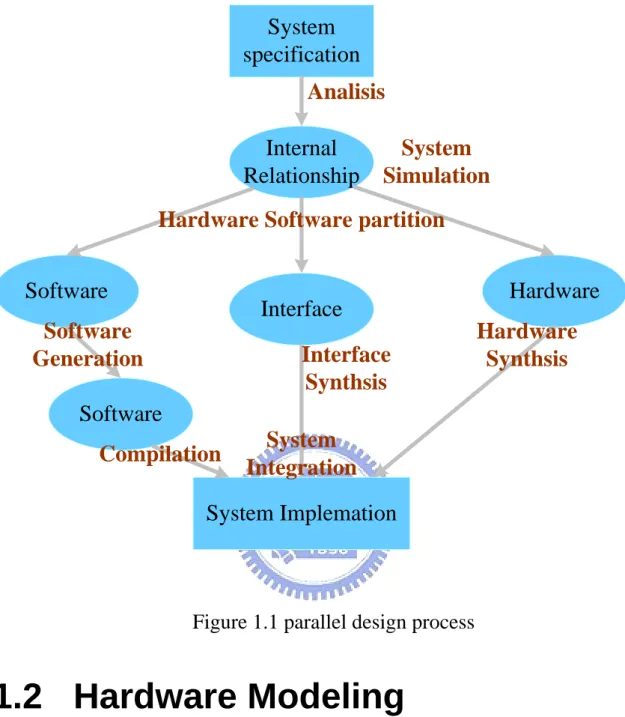
(8) Chapter 1 Introduction 1.1 SoC Design process The increasing technological complexity coupled with requests for high performance and time-to-market requires for new design methodologies and tools for System-on-Chip (SoC) products. To meet performance requirements and to achieve shorter development cycles, the IC design development process will be different from the traditional ASIC development process. As shown in Figure 1.1, IC designs have been extended from the traditional sequential development process to parallel development process. Usually, SoC design starts from a high abstraction specification which consist mainly one or a few functional subsystems. The next step is to create the system simulation and then explore the internal relationship among subsystems. The hardware/software partition is made followed by an architecture and interface definition. Implementing the hardware with hardware description language and transferring software to executable codes are the next step. Finally, the last step is to integrate all components into one system.. 1.
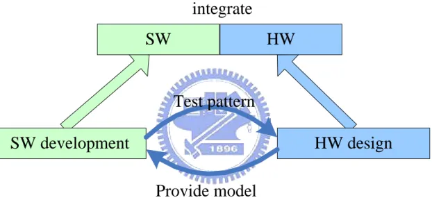
(9) System specification Analisis Internal Relationship. System Simulation. Hardware Software partition Software. Interface. Software Generation. Interface Synthsis. Hardware Hardware Synthsis. Software Compilation. System Integration. System Implemation. Figure 1.1 parallel design process. 1.2 Hardware Modeling The major difference between traditional and modern design processes is that the goal of modern process is to enable parallel software and hardware development. In order to finish software development and verification prior to the hardware can be completed, a hardware model becomes essential. Figure 1.2 shows that the hardware design team provides hardware models for software development and software design team generates test patterns for hardware verification. In decade, hardware modeling technologies have been investigated widely. For general functions running on processor, most 2.
(10) researches, such as [3-4] are focus on instruction set simulators. For a dedicated functional hardware, there are also lots publications, such as [2] wants to enable the use of a single model for multiple proposes throughout a design process, [3] presents two co-simulation methodologies models, [4] focuses on the timing information of models, [5] addresses the expanding of the software design cycle to the integrated hardware modeling and simulation, and [6] presents a fast prototyping method for software and hardware designs.. integrate SW. HW. Test pattern SW development. HW design Provide model. Figure 1.2 parallel software and hardware development. 1.3 Communication SoC Design. 3.
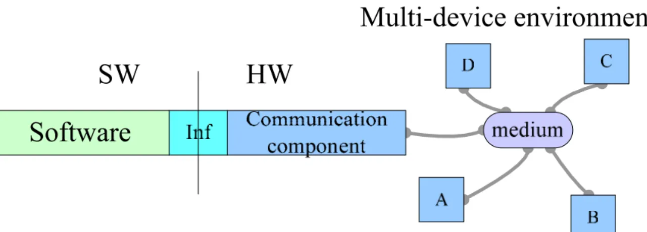
(11) Figure 1.3 Communication device design For communication SoC designs, the previous studies are not enough. Above hardware modeling studies concentrate on how to model the hardware that can not be implemented, but the hardware modeling technologies are not suitable for a communication system. Because the main functions of the communication hardware are for exchanging messages and maintaining the connection with other devices, their behaviors are highly coupled with not only the hardware itself but also connection channels and other devices. It is very different from the conventional hardware which is only used for data processing and provides service for the processor or other master components. If we just model the hardware itself, it is impossible to be used to verify the software. Figure 1.3 shows that communication device’s behaviors are coupled with not only the physical layer itself but also the medium and other devices. Taking wireless medium access control (MAC) as the example, most functions are used to control the access of the shared medium by defining rules for multi-device communication with orderly manner. Therefore, such 4.
(12) functions can only be verified in multi-device environment. As a result, in conventional design process, verification of communication functions can only be started at the late of the design flow. To solve this problem, we propose a simulation platform including hardware modeling. The modeling platform includes a multi-device communication environment in the hardware model. Such that, the model can emulate the behavior of communication devices under shared channels and will interact with other parallel components. This will provide the benefit of moving the functional verification to an early design cycle. Before the hardware can be completed, co-simulating with the hardware model, all communication functions could then be verified, such as the channel access, channel time management, and so on.. 1.4 Motivation Hardware modeling is an important issue in SoC design process, and system simulation is an essential process in communication system designs. For communication SoC designs, a platform combined these utilities is especially important. As result, a development and verification platform is created to enables the use of a single platform for multiple-purpose communication system designs, including system simulation, software development, and hardware modeling.. 1.5 Organization This paper is organized as follows: This chapter, we present the hardware modeling in parallel design process and finger out its drawback 5.
(13) for communication soc design. In chapter 2, the simulation and modeling platform and the design methodologies of each component are presented. Chapter 3 shows a case example for the proposed design approach. Conclusion and possible future works are discussed in chapter 4.. 6.
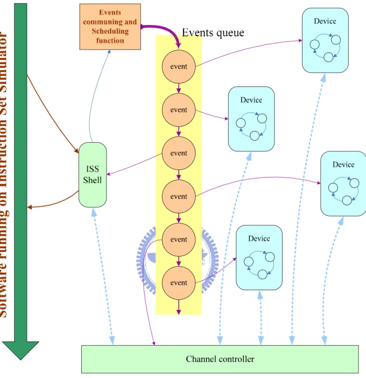
(14) Chapter 2 Platform Design Methodology 2.1 Overview Figure 2.1 shows the key components and their connections of the proposed simulation and modeling platform. The platform is basically composed of five components: Event Queue, Virtual Devices, Channel Controller, Instruction Set Simulator, and ISS shell. The first three items construct the system simulator. With these components, the system simulation platform can be used to develop new control protocols. The last two items are key components which perform instruction level simulation and hardware modeling. The following subsections will present each component’s design methodology.. 7.
(15) Figure 2.1 the platform architecture. 2.2 Event Queue In an effort of performing the multi-device simulation, the most important features that should be handled are the parallel execution and 8.
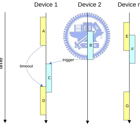
(16) timing synchronization. Figure 2.2 shows the parallel execution problem: all tasks in devices execute parallel, there will be more than two tasks executing at the same time, and they may be interact with each other. Whether a task will be triggered may be depended on the other device which is parallel executed. By intuition, the multi-tasking execution controls capability provided by the operation system might be useful to provide parallel execution, such as, multithreading, processes, or pipes. Taking the advantage of endowing each device with an individual task, we can perform parallel execution naturally.. Device 1. Device 2. Device n. A E B F trigger timeout C. D G. Figure 2.2 parallel execution problem. Nevertheless, when we run into the second issue: timing synchronization, the multi-task application will make this problem more difficult to solve 9.
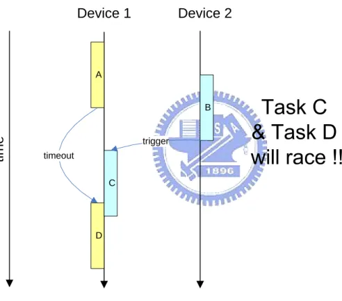
(17) efficiently. As shown in Figure 2.3, in a simulation, there will be many race conditions, and different order of events will cause different simulation result. In order to ensure the accuracy of the simulation, it is necessary to make all devices have the same timing. Because of this, the platform must insert a large amount of synchronization points on every task. It leads to a large leakage of simulation time in context switch and busy waiting.. Device 1. Device 2. A. time. B. trigger timeout C. D. Figure 2.3 timing synchronization problem. For. the. purpose. of. handling. parallel. execution. and. timing. synchronization efficiently, the approach of separating the invocation and execution of events is adopted to gather all execution of functions and timer interrupts from different devices, and then form a central event queue. 10.
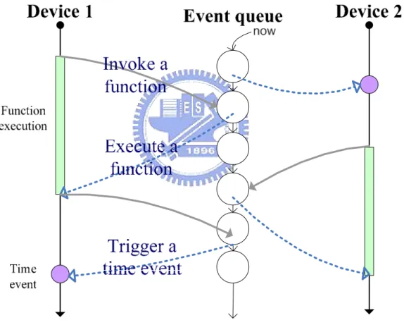
(18) The queue is a priority queue based on execution delay. Items in the queue are constructed by an execution delay and a reference of function invocation. When a device executes a function, it packages the estimated execution delay and the invocation of the function instead of really executing, and then pushes it to the event queue. The working flow of an event queue is illustrated in Figure 2.4, where the event queue is reduced when system runs and time escapes.. Figure 2.4 event queue working flow. 2.3 Virtual Devices Virtual Devices are the key role of the system simulation. It can be 11.
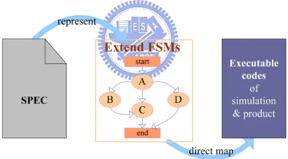
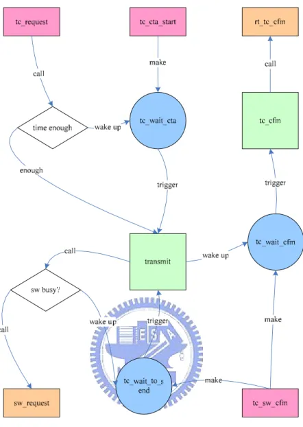
(19) divided into three modules. The first module is the connection of the upper layer. Since the target is communication functionalities, we create a traffic feeder in stead of real applications. The feeder reads traffic files and feeds them into devices. The second module is the implementation of protocol functionalities. In the communication protocol specification, functionalities are always written in natural language and some of them are illustrated with message sequence charts, as a result, they are plagued by ambiguities and incompleteness and are always difficult to create executable codes. Realizing the problems, we adopt a two-step solution, shown in Figure 2.5, where a medium is introduced between specification and executable codes.. Figure 2.5 a two-step solution for code generation. The medium defines an Extended Finite State Machine Specification and its description guidelines. Figure 2.6 shows an Extended Finite State Machine example. The Extended Finite State Machine haves five state 12.
(20) types: input state, output state, waiting state, decision state, and procedure state. The input states are services for upper or lower layers. The output states are links to adjacent states. The waiting states are used for conditional execution. The decision states change the execution’s direction. The procedure states trigger data process. By transforming the specification into State Machine, we can overcome problems caused by ambiguities, replenish lack of specification, and even repair errors. After State Machines are finished, we just need to follow a regular rule and translate the State Machine to executable codes. In the future, the translation can be automatically done by a code generator. This further reduces the software development time. The third module of virtual devices is the interface to lower layers. It depends on a specific communication system and its hardware/software interface. The third module also includes a hardware model of lower protocol stacks.. 13.
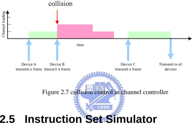
(21) Figure 2.6 an Extended Finite State Machine example. 2.4 Channel Controller In the simulation platform, if a device wants to send a message to the other one, it should pass it through a channel controller. The channel controller simulates the channel condition which devices will use to exchange messages. The channel controller simulates the collision, channel noise, and hidden node effect, and so on. Figure 2.7 shows a basic collision control in channel controller, it use a channel loading counter to record the 14.
(22) number of device whose transmitter are active, and use the counter to determine whether the frame will be passed to devices whose receiver is active or not. With different communication systems and channel characteristics, the simulated channel controller will be also different.. Figure 2.7 collision control in channel controller. 2.5 Instruction Set Simulator Instruction Set Simulators are software environments which can read microprocessor instructions and simulate their executions. Most of these tools can provide simulations results like values in memory and registers, as well as timing information (e.g. clock cycle statistics). Thus, instruction set simulator provides an environment for software development on targeted microprocessor, and allows cycle-accurate benchmarking and validation of targeted software. Depending on the target microprocessor, the instruction set simulator in the platform will be different. The proposed platform can link to many existing instruction set simulator provided by the microprocessor’s vendor. In order to be used in the platform, the instruction 15.
(23) set simulator should support the following functionalities: 1. exchanging data with outer environment. 2. stop and hold, when writing out a data. 3. resuming after stopped. 4. stop after certain cycles prescheduled. 5. changing internal signals, when stopped. If the emulation board with real microprocessor supports these functionalities, then it can be used in our proposed platform.. 2.6 ISS Shell ISS shell is the component which carries out hardware modeling and connects the Instruction Set Simulator to simulation platform. It is responsible. for. modeling. the. hardware. parts,. keeping. timing. synchronization, and exchanging data between the system and the Instruction Set Simulator. Data exchanging and synchronization flow are shown in Figure 2.8. Running example: 1. Event queue controller reads next event, and then set a break point on the instruction set simulator based on the time delay of next event. 2. ISS runs and requests for sending data to ISS shell. Then it causes an active break. 3. The event queue controller updates the system timing and then ISS shell passes the data to channel controller. 4. System makes the action and the event queue is updated. Base on the action, the break point is rescheduled. 16.
(24) 5. ISS runs and is trapped into a break point. If the channel controller is going to send data to ISS, it passes the data to ISS through ISS shell. After above actions, return to step 1 and then repeat the above procedure.. Figure 2.8 data exchanging and synchronization flow. 17.
(25) Chapter 3 A Case Example: UWB MAC 3.1 Overview The IEEE 802.15.3 wireless standard is a candidate of wireless personal area networks and aim to achieve fast connection time, Ad hoc networks, Data transport with QoS, dynamic membership and efficient data transfer. Wireless personal area networks (WPANs) are used to convey information over relatively short distances among a relatively few participants. Unlike wireless local area networks (WLANs), connections effected via WPANs involve little or no infrastructure. This allows small, power efficient, inexpensive solutions to be implemented for a wide range of devices. Because of this, its MAC design is of great importance and full of challenge. So, we employ our platform to help its MAC research and design. First, we use our platform for MAC superframe formation and channel time management research. Since the device-orient simulation and effort for efficiency, the simulation is more accurate and even ten times faster than the old simulator we used. Second, we apply our modeling platform to assist partition definition and support MAC software development before hardware is finished.. 3.2 IEEE 802.15.3 MAC Protocol 18.
(26) 3.2.1 The 802.15.3 piconet and its components 802.15.3 is based on a centralized and connection-oriented ad-hoc networking topology. This wireless ad hoc data communications system which allows a number of independent data devices (DEVs) to communicate with each other is called piconet. A piconet is distinguished from other types of data networks because communications are normally confined to a small area around person or object that typically covers at least 10m in all directions and envelops the person or a thing whether stationary or in motion. This is in contrast to local area network (LAN), metropolitan area network (MAN), and wide area network (WAN), each of which covers a successively larger geographic area, such as a single building or a campus or that would interconnect facilities in different parts of a country or of the world. An 802.15.3 piconet consists of several components, as shown in Figure 3.1. The basic component is the DEV. One DEV is required to assume the role of the piconet coordinator of the piconet (PNC). The PNC provides the basic timing for the piconet with the beacon. Additionally, the PNC manages the quality of service requirements, power save modes and access control to the piconet.. 19.
(27) Figure 3.1 the IEEE 802.15.3 piconet. The 802.15.3 standard allows a DEV to request the formation of a subsidiary piconet. The original piconet is referred to as the parent piconet. The subsidiary piconet is referred to as either a child or neighbor piconet, depending on the method the DEV used to associate with the parent PNC. Child and neighbor piconets are also referred to as dependent piconets since they rely on the parent PNC to allocate channel time for the operation of the dependent piconet. An independent piconet is a piconet that does not have any dependent piconets.. 20.
(28) 3.2.2 The 802.15.3 Superframe Structure Timing in the 802.15.3 piconet is based on the superframe, which is illustrated in Figure 3.2. The superframe is composed of three parts: — The beacon, which is used to set the timing allocations and to communicate management information for the piconet. — The contention access period (CAP), which is used to communicate commands and/or asynchronous data if it is present in the superframe. — The channel time allocation period (CTAP), which is composed of channel time allocations (CTAs), including management CTAs (MCTAs). CTAs are used for commands, isochronous streams and asynchronous data connections.. Figure 3.2 superframe structure. The length of the CAP is determined by the PNC and communicated to the DEVs in the piconet via the beacon. The basic medium access mechanism during the CAP is carrier sense multiple access with collision avoidance (CSMA/CA). To minimize collisions, a transmitting DEV is 21.
(29) required to first sense whether the medium is idle for a random length of time, called “backoff interframe space” (BIFS). Only if the medium is idle after that time shall the DEV start its transmission. This process of waiting before transmission is termed “backoff.” The backoff count is random selected from range (0,BW), where BW means backoff window, which is a table has values [7, 15, 31, 63]. For the first transmission attempt of a frame, the BW value is set to the minimum number 7. If collision occurs, the BW value should be increased to the next larger value until the maximum value 63. The DEV shall maintain a counter for backoff count which is decremented only when the medium is idle. Whenever the channel is busy, the backoff counter shall be suspended. The channel shall be determined to be idle for the duration of a BIFS period before the backoff slot countdown is resumed. When the backoff counter reaches zero, the DEV may transmit a frame.. On the other hand, channel access in the CTAP is based on a TDMA method. The PNC divides the CTAP into channel time allocations (CTAs). A DEV that is given a directed CTA is guaranteed that no other DEVs will compete for the channel during the indicated time duration of the CTA. A DEV with a CTA may or may not make use of all the allocated time duration within the CTA. The selection of a stream, command or asynchronous data for transmission during a CTA is determined locally by the DEV depending on the number of pending frames and their priorities. All CTAs have guaranteed start time and duration. The guaranteed start times enable both power saving and good QoS characteristics. All the CTAs for the current superframe are broadcast in the beacon. 22.
(30) 3.2.3 Layer management Both MAC and PHY layers conceptually include management entities, called the MAC sublayer management entity and PHY layer management entity (MLME and PLME, respectively). These entities provide the layer management service interfaces for the layer management functions.. Figure 3.3 The reference model used in IEEE 802.15.3 standard. In order to provide correct MAC operation, a device management entity (DME) should be present within each DEV. The DME is a layer-independent entity that may be viewed as residing in a separate management plane or as residing “off to the side.” The exact functionality of the DME is not specified in this standard, but in general this entity may 23.
(31) be viewed as being responsible for such functions as the gathering of layer-dependent status from the various layer management entities, and similarly setting the value of layer-specific parameters. The DME typically performs such functions on behalf of the general system management entities and implements standard management protocols. Figure 3.3 depicts the relationship among the management entities.. The various entities. within this model interact in various ways. Certain of these interactions are defined explicitly within the standard, via a service access point (SAP) across which defined primitives are exchanged. Other interactions are not defined explicitly within this standard, such as the interface between the MAC and the MLME or the interface between the PHY and the PLME. The specific manner in which these MAC and PHY interfaces are integrated into the overall MAC and PHY layers are not specified within this standard. In the thesis, we focus on the implementation of the MAC/MLME layer. In the next subsection, we will analyze and present MAC/MLME functions.. 3.3 MAC functions 3.3.1 Overview. 24.
(32) Traffic generator Informatio n element buffer Stream output buffer. CTA managem ent. qu re. request. t es. Command buffer. fragmenta tion. retransmis sion. retransmis sion. Beacon generator. Superfram e control. Stream input buffer. Beacon decoder. defragmen tation. setup. CAP control. CTA control. Send and Wait. ACK. CCA. TX. en d. dispatch. RX. Channel. Figure 3.4 MAC functional stack 25. Command buffer.
(33) In this thesis, we apply our platform to the development of MAC/MLME layer in IEEE 802.15.3 specification. In the first place, we analyze the MAC/MLME protocol and partitioned it into the function stack as shown in Figure 3.4. As Figure 3.4 shows, the output control mechanism in MAC/MLME can be partition into blocks: output buffer, fragmentation, retransmission, timing control, acknowledge control, and physical layer interface. When the MAC layer receives a data transmission request from its upper layer, the data will be put into the output buffer, the request time will be recorded at the same time. The output buffer controller will transmit the data in the front of the output buffer sequentially and setup a transmission timeout timer which is depend on the request time and delay bound. The fragmentation control block will fragmentize the data into slices immediately, when it receive a data from the output buffer. The sizes of each slice are depended on the device’s system parameter and the data size. The block following the fragmentation control block is the retransmission control block. When receiving a request, the retransmission control block will pass it to its lower layer and start to wait for a result confirm. If the lower layer confirm with a successful result, the retransmission control block will confirm the fragmentation control block with a success result. If the lower layer confirms that the transmission is failed, the retransmission control block will make the decision to drop the frame and confirm with false or retransmit and increase the retransmission counter. The followed block is CTA timing control, the block is used to make sure that the data transmission is in its CTA time slot. The block will estimate the total processing time of the data and determinate whether the 26.
(34) data will be transmitted immediately or wait for next CTA time slot. Send-and-Wait is an acknowledge control block. When a transmission is finished, it will switch the physical layer to a receive mode, starting to wait for an ACK from the destination device, and setup a timeout timer. The input control mechanism in MAC/MLME can be partitioned into blocks: dispatch, acknowledgement and frame handler of every frame types. When physical layer receives a frame, it will send an indication to the dispatch block. After receiving an indication, the dispatch block will decode the frame and send the frame to its corresponding block. For example, the data frame will be send to the defragmentation block and trigger the ACK block to return an ACK to the source device. The following subsection will introduce some blocks.. 3.3.2 Stream output buffer The stream output buffer is used to serve the request from MAC’s upper layer. When the MAC receives a data transmission request from its upper layer, the data will be pushed into the output buffer which is based on first-in-first-out queue, the request time will be recorded at the same time. The output buffer controller will transmit the data in the front of the output buffer and setup a transmission timeout timer which is depend on the request time and delay bound. If the timeout timer reaches to zero before the success of the transmission, the block will send a clear request to its lower layer to drop the unfinished procedure of the data transmission, popping the front data of the buffer and start to transmit the next data in the buffer. On the contrary, if the lower layer confirms with a successful result 27.
(35) before the timer reaches to zero, the output controller will stop the timer and prepare to transmit next data in the buffer. Figure 3.5 shows the state diagram of the stream output buffer.. so_req. so_cfm. So_clr. result call. call call so_finish so_clear. fg_status trigger. result:fail. Idle:call. so_transmit. wake up. so_wait_ cfm. make so_timeout wake up call. call call. fg_cfm. trigger. fg_request. so_wait_ timeout. fg_clr. Figure 3.5 stream output buffer function block’s state diagram. 3.3.3 CTA Timing Control The CTA Timing Control function block is used to make sure that the data transmission is in CTA time slot in the superframe. There are two 28.
(36) entries can be used to trigger the mechanism. The first is the transmission request from the upper layer. When it receives a request, it will estimate total processing time of the data’s transmission and determine whether the data will be transmitted or suspended. The second is the CTA timeslot start indication. When the CTA timeslot start indication is received, the CTA timing controller will check whether there is a data being suspended or not. If there is data that was been suspended, it will resume the data transmission.. tc_req. cta_stat. tc_cfm. tc_clr. call call. make sw_status Idle: call. busy: call. call trigger. time_enough. No: wake up. re_finish. tc_wait_ cta. Yes: call tc_wait_ sw. trigger. trigger. tc_clear tc_transmit. wake up tc_wait_ cfm. make. call. call make. tc_request. tc_cfm. tc_clr. Figure 3.6 CTA timing control function block’s state diagram 29.
(37) 3.3.4 Send and Wait In IEEE802.15.3 Specification, if the source device wishes to verify the delivery of a frame, then the acknowledgement policy is used. The immediate-ACK policy provides an ACK process in which each frame is individually ACKed following the reception of the frame. If the source device does not receive the requested ACK, then it has the option of retransmitting the frame or dropping the frame. The Send and Wait controller block is a acknowledge control block used to handle the above process. When a transmission is finished, it will switch the physical layer to receive mode, start to wait an ACK from the destination device, and setup a time exceeded timer. If the requested ACK is received before the timer reach zero, it will confirm with success transmission result. Otherwise, it will confirm its upper layer with transmission failed result and let its upper layer to make the decision to retransmit or drop the frame.. 30.
(38) Figure 3.7 Send and Wait function block’s state diagram. 3.3.5 CAP Timing Control The basic medium access mechanism during the CAP is carrier sense multiple access with collision avoidance (CSMA/CA). To minimize collisions, a transmitting DEV is required to first sense whether the medium is idle for a random length of time. Only if the medium is idle after that time shall the DEV start its transmission. This process of waiting before transmission is termed “backoff.” The backoff count is random selected from range (0,BW), where BW means backoff window, which is a table has values [7, 15, 31, 63]. For the first transmission attempt of a frame, the BW value is set to the minimum number 7. If collision occurs, 31.
(39) the BW value should be increased to the next larger value until the maximum value 63. The DEV shall maintain a counter for backoff count which is decremented only when the medium is idle. Whenever the channel is busy, the backoff counter shall be suspended. The channel shall be determined to be idle for the duration of a BIFS period before the backoff slot countdown is resumed. When the backoff counter reaches zero, the DEV may transmit a frame.. 32.
(40) Backoff request. CAP start make. make. Wait for Starting. trigger Wait for CAP start. trigger. wake up. frame. wake up. wake up Read profile. Suspend all. wake up. Check channel status. Wait for CAP end. setup. Wait for Channel idle. trigger. trigger make CAP end. trigger. Setup. make. CCA status. start. Backoff counter. wake up. wake up. make. make Wait for channel busy. mutual. Wait for counter equal zero. trigger. wake up. transmit. stop. trigger. suspend. Figure 3.8 CAP timing control function block’s state diagram. 33.
(41) 3.4 ARMulator 3.4.1 A Instruction Set Simulator for ARM The ARMulator is a family of programs which emulate the instruction sets of various ARM processors and their supporting architectures. The ARMulator: · provides an environment for the development of ARM-targeted software on a range of non-ARM-based host systems · allows accurate benchmarking of ARM-targeted software (though its performance is somewhat slow compared to real hardware) · supports the simulation of prototype ARM-based systems, ahead of the availability of real hardware, so that software and hardware development can proceed in parallel. The ARMulator is transparently connected to the ARM debuggers to provide a hardwareindependent ARM software development environment. Communication takes place via the Remote Debug Interface (RDI). The ARMulator comprises several parts: · A model of the ARM processor core and cache (if used) · A base memory model (armflat) incorporating address decoding. This causes the relevant peripheral model to be accessed when memory within its registered range is addressed. · Peripheral models that communicate with the base memory model and may be enabled or disabled via configuration files. · An operating system interface to provide an execution environment. By modifying or rewriting the supplied models, you can model almost 34.
(42) any ARM system and use it to debug code. The following diagram illustrates this structure1.. Figure 3.9 ARMulator structure. 3.4.2 Modeling in ARMulator ARMulator supports IP designers to design their IP’s hardware model for simulation. A new device can be designed with C/C++ language using certain predefined functions interface for the hardware modeling with ARMulator. The designs are built as dynamic link libraries (DLLs). By adding IP’s hardware model’s DLL and modifying corresponding component description parameters, the hardware model can be included into the simulation. An ARMulator hardware model must include ARMulator basic model interface. 35.
(43) A basic model interface includes three parts: 1. Data structure declaration 2. Initialization 3. Finalization Data Structure Declaration: Data structure is declared using BEGIN_STATE_DECL() and END_STATE_DECL() macros. Private data structure is declared as follow. BEGIN_STATE_DECL(YourModel) /* * your private data here */ END_STATE_DECL(YourModel). These macros declare a data structure: Typedef struct YourModelState This data structure includes your private data you put between the macros and the following predefined data fields: Toolconf config Const struct RDI_HostInterface *hostif RDI_ModuleDesc coredesc RDI_ModuleDesc agentdesc Initialization We use BEGIN_INIT() and END_INIT() macros to delineate the initialization functions of the model. In the initialization function, your 36.
(44) model must initialize any private variable and install any callback. Two variables are provided in the initialization: Î Bool coldboot TRUE if ARMulator is initializing, FALSE if a new image is being downloaded from the debugger. ÎYourModelState *state A pointer points to the private state data structure. Memory for this is allocated and declared by the initialization macro, and the predefined data fields are initialized. Finalization We use BEGIN_EXIT() and END_EXIT() macros delineate the finalization function for the model. The finalization function is called when ARMulator is closing down. The following local variable is provided in the finalization function: YourModelState *state Your model must un-install any callbacks in the finalization function. The END_EXIT() macro frees memory allocated for state.. 3.5 Link ARMulator with the system simulation To link ARMulator with our simulation platform, there are three key functions supported by ARMulator are used: TICRegisterAccess, ARMulif_SetSignal,. ARMulif_ScheduleNewTimedCallback.. All. data. transmission between ARM core and hardware model are through memory 37.
(45) map registers. The function TICRegisterAccess is used to deal with the memory access in the hardware model. When the software running in the ARM core needs to pass a message to the hardware model, it call TICRegisterAccess directly with parameters that are used for writing. When the hardware model needs to pass a message to the software part, it trigger. an. interrupt. of. ARMulator,. and. ARMulator. will. call. TICRegisterAccess with parameters that are used for reading mode to read the message. The ARMulif_SetSignal is the function used to trigger an interrupt to the ARMulator. ARMulif_ScheduleNewTimedCallback is the function used to synchronize the ARMulator and our hardware model as described in subsection 3.6. Figure 3.11 is a running snap show of UWB MAC running on the platform.. Figure 3.10 co working chart. 38.
(46) Figure 3.11 a running snap show. 39.
(47) Chapter 4 Conclusion and Future Works The beginning of this paper brings up that hardware modeling is an important part of hardware/software co-design process in the SoC design trend. Especially for MAC designs, which are highly coupled with other devices, a platform based on combined multi-device environment and hardware models is needed and developed. The platform can be partitioned into five main components: Event Queue, Virtual Devices, Channel Controller, Instruction Set Simulator, and ISS Shell. The descriptions of each component and the design strategies are also provided in this thesis. Combining multi-device environment simulation and hardware modeling, the platforms provides a hardware model interacting with other parallel virtual devices. During software development process, designer could use the platform to do performance prediction and functional verification. According to the extension of the system-level simulation, the platform could also verify algorithms at the protocol level by the system-level simulation. In this thesis, the established simulation platform has been applied to UWB MAC designs as a example. The future work is to enhance the platform’s capability and spans its applications. The possible work will include the employing of SystemC library to enhance hardware modeling capability, to develop a program translator to generate software codes automatically and to create a friendly graphic interface of the platform.. 40.
(48) Reference [1] M. Keating and P. Bricaudr, Reuse Methodology Manual for System-On-A-Chip Designs, Kluwer Academic Publishers, 2002 [2] Silbermintz, M.; Sahar, A.; Peled, L.; Anschel, M.; Watralov, E.; Miller, H.; Weisberger, E.; ”SOC modeling methodology for architectural exploration and software development”, ICECS, pp. 383-386, 2004 [3] Fummi, F.; Martini, S.; Perbellini, G.; Poncino, M.; “Native ISS-SystemC integration for the co-simulation of multi-processor SoC” Design, Automation and Test in Europe Conference and Exhibition, pp. 564-569, 2004 [4] Luca Formaggio; Franco Fummi; Graziano Pravadelli;”A timing-accurate HW/SW co-simulation of an ISS with SystemC” IEEE/ACM/IFIP international conference, pp. 152-157, 2004 [5] Agrawal, A.; Ledeczi, A.;”Multigranular simulation of heterogeneous embedded systems”, Engineering of Computer-Based Systems, pp. 3-10, 2003 [6] Hoffmann, A.; Kogel, T.; Meyr, H.;”A framework for fast hardware-software co-simulation”, Design, Automation and Test in Europe, pp. 760-764, 2001 [7] Andrei Alexandrescu, Modern C++ Design, Addison-Wesley, 2001 [8] Xiao, Z.; Randhawa, T.S.; Hardy, R.H.S.;”A State-Machine Based Design of adaptive Wireless MAC Layer”, Vehicular Technology Conference, pp. 2837-2841 vol.4 2003 [9] ARM Limited, “ARM Developer Suite – Debug Target Guide, Version 1.2” 41.
(49) [10] Oussorov, I.; Raab, W.; Hachmann, U.; Kravtsov, A.; “Integration of Instruction Set Simulators into SystemC High Level Models”, Digital System Design, pp. 126-129, 2002 [11] IEEE Standard for Information technology Telecommunications and information exchange between systems Local and metropolitan area networks Specific requirements Part 15.3: Wireless Medium Access Control (MAC) and Physical Layer (PHY) Specifications for High Rate Wireless Personal Area Networks (WPANs). [12] ARM Application Note 32: The ARMulator [DAI0032E] [13] ARM Debug Target Guide [DUI0058D] [14] DaYu, Chiu; YuChen, Sun; ChingYao, Huang;, “A Modeling and Verification Platform for Communication SoC designs”, VLSI/CAD Design 2005.. 42.
(50) 簡歷 邱大瑜,1981 年 1 月 27 日生於台灣台中縣。畢業於,台中第一高級中 學,交通大學電子工程學系,交通大學電子所。. 43.
(51)
數據
+7
Outline
相關文件
• Uses a nested structure to accumulate path data as the simulation is running. • Uses a multiple branch structure to choose the
For terminating simulations, the initial conditions can affect the output performance measure, so the simulations should be initialized appropriately. Example: Want to
The simulation environment we considered is a wireless network such as Fig.4. There are 37 BSSs in our simulation system, and there are 10 STAs in each BSS. In each connection,
The objective of the present paper is to develop a simulation model that effectively predicts the dynamic behaviors of a wind hydrogen system that comprises subsystems
“A Comprehensive Model for Assessing the Quality and Productivity of the Information System Function Toward a Theory for Information System Assessment.”,
In this thesis, we develop a multiple-level fault injection tool and verification flow in SystemC design platform.. The user can set the parameters of the fault injection
Community of practice provides a platform for knowledge workers to share, learn and discuss the knowledge related to a particular topic, thus, the performance of the community
The main purpose of this paper is using Java language with object-oriented and cross platform characteristics and Macromedia Dreamweaver MX to establish a JSP web site with
