Three-dimensional microscopy through liquid-lens axial scanning
Ana Doblas, E. Sánchez-Ortiga, G. Saavedra, J. Sola-Pikabea, M. Martínez-Corral
Department of Optics, University of Valencia, E-46100, Burjassot, Spain
[email protected], [email protected], [email protected], [email protected]
Po-Yuan Hsieh, Yi-Pai Huang
Department of Photonic and Display Institutes, National Chiao-Tung University, Hsinchu 30010, Taiwan
[email protected], [email protected]
ABSTRACT
In this contribution we propose the use of a liquid lens (LL) to perform three-dimensional (3D) imaging. Our proposed method consists on inserting the LL at the aperture stop of telecentric microscopes. The sequential depth images of 3D samples are obtained by tuning the focal length of LL. Our experimental results demonstrate that fast-axial scanning of microscopic images is obtained without varying neither the resolution capability nor the magnification of the imaging system. Furthermore, this non-mechanical approach can be easily implemented in any commercial optical microscope.
Key words: 3D microscopy, Telecentricity, Axial scanning, Liquid lens
To increase and improve our knowledge of biological processes, three-dimensional (3D) live imaging is a re-quired tool due to the information provided in 2D live imaging contains only a partial representation of the 3D process-es. It is worth to mention that since no 3D sensors are available to record the 3D image of a specimen, the 3D image is composed computationally after recording a stack of 2D images while stepping the object through the in-focus plane [1-11]. Nevertheless, the main drawbacks of the mechanical scanning of smaples are a decrease of the acquisition speed and the presence of distortions due to alignment mismatches in imaging systems.
In order to acquire the 3D volume of a microscopic sample avoiding the mechanical movements, different ap-proaches has been already published. One solution is digital holographic microscopy (DHM) [12, 13] in which the 3D complex distribution scattered or transmitted by a sample is directly captured. Although with this technique different sections of the specimen can be computationally refocused, the imaging system operates coherently impeding fluores-cence imaging. This issue can be solved using light-field microscopy (or integral-imaging system) [14, 15]. However, the acquisition of the 3D distribution compromises the lateral resolution obtained which is significantly decreased.
Recently, a different approach has been proposed to face the task of 3D imaging. This method uses an elec-tronically-tunable lens (ETL) to scan the object plane and it has already been implemented in integral-imaging system [16], two-photon microscopy [17], light-sheet microscopy [18] and confocal microscopy [19, 20]. Notwithstanding, in these works there is not a symmetrical shifting of the object plane and neither the lateral resolution nor the magnifica-tion remain invariant.
In our proposal, we insert a liquid lens (LL) [21, 22] at the aperture stop of a conventional widefield micro-scope to focus different parts within a sample without any mechanical movement with constant magnification and reso-lution and with symmetrical displacement range.
Firstly, let us start by describing the theoretical background of widefield microscopy. A scheme of this micro-scope is shown in Fig. 1. The object plane in which the specimen is focused is placed at the front-focal plane (FFP) of the microscope objective (MO). Note that this position is provided by the working distance (WD) which denotes the distance between the front lens element of the MO and the object plane. From this figure it is easy to realize that since the wavefield emanating from the MO is collimated, a converging lens, usually known as tube lens (TL), is required to produce a real, inverted, magnified image of the object at its back-focal plane (BFP).
In order to provide high-resolution images, the MO operates in telecentric regime in the object space, which means that the aperture stop is placed at its BFP. Besides, note that conveniently the optical arrangement between the MO and the TL is also telecentric, the BFP of MO corresponds to the FFP of TL. The telecentricity property provides us some advantages. Firstly, the lateral magnification of the imaging system (M= − fTL' / f
MO
' ) does not depend on the axial position of the sample image. This statement is really useful in 3D microscopy due to the magnification remains invariant during the scanning process of the 3D volume of the sample. Secondly, it exists a linear relation between ob-ject coordinates and image coordinates given by
Invited Paper
Three-Dimensional Imaging, Visualization, and Display 2015, edited by Bahram Javidi, Jung-Young Son, Proc. of SPIE Vol. 9495, 949503 · © 2015 SPIE
CCC code: 0277-786X/15/$18 · doi: 10.1117/12.2177680 Proc. of SPIE Vol. 9495 949503-1
Object plane Aperture Stop MO Image plane WD HI f TL (a) MO (b) MO (f'MO) LL (f IL)
Pik
414
LL I I ( IFMO 1111.1 MO FMOI FT
F'MO-F'T
111,
I I .f'MO.f'MO °f'T
01 x '= Mx σ'=σ / M z'= M2z , (1)being (x,σ ,z) and (x',σ ',z') the transverse, angular and axial coordinates at the object and image plane.
Fig. 1 Scheme of a conventional widefield microscope. The optical arrangement between the microscope objective (MO) and the tube lens (TL) follows an afocal configuration.
Other advantage of telecentric optical microscopes is that they are 3D linear and shift invariant (LSI) in ampli-tude and intensity. This claim implies that the 3D image is obtained as the 3D convolution between a uniformly scaled copy of the object and a 3D function which is usually known as the intensity PSF [1, 4]. It is important to mention that the spatial resolution of any optical system can be evaluated by analyzing the intensity PSF [4].
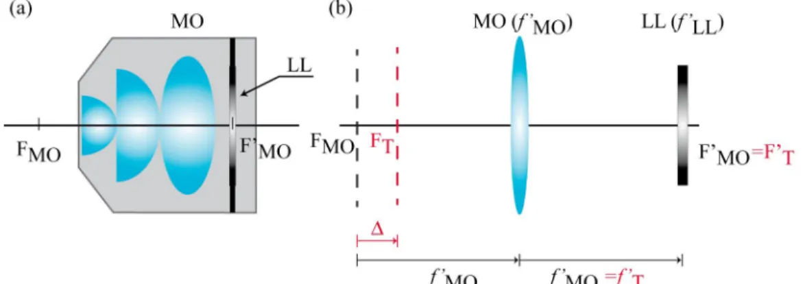
Our aim here is to obtain a fast axial-scanning widefield microscope. To face this task, we build a prototype MO in which a LL is inserted at the BFP of the MO, see Fig. 2(a). In Fig. 2(b), it is shown how the optical parameters of our prototype are modified by the insertion of the LL. To simplify the drawing, the MO is schematized through a thin lens. From Fig. 2(b), it is evident that the compound system acts as a lens whose focal length ( fT
') and BFP ( F T) are not affected by the presence of the LL. However, the location of the position of FFP (FT
') is shifted by a distance Δ which depends on the focal length of the LL, Δ = fMO
'2 / f
LL
' . Note that a diverging lens produce negative displacements (away from the MO) and a converging lens produces positive displacements (towards the MO).
Fig. 2 (a) Illustration of our prototype MO in which a LL is inserted at the BFP. In panel (b) it is shown how the optical parameters are modified by the LL.
The use of our prototype in an optical microscope could be advantageous for 3D imaging. Let us imagine a widefield microscope, like the one depicted in Fig. 1, in which the regular MO is replaced by our proposed MO, see Fig. 2(a). In such case the sequential focusing of different sections within a sample are obtained by tuning the focal length of LL while the position of the image plane remains invariant. Besides, as the coupling between the MO and the LL does not modify the BFP and the focal length, the imaging system preserves the telecentricity property. This means that the relationship between the object plane and image plane is linear and given by Eq. (1) and the system is still 3D LSI. On the other hand, if the effective diameter of the LL and the aperture stop fit properly, the intensity PSF is also the same, so the resolution is not affected.
Proc. of SPIE Vol. 9495 949503-2
Object plane
MO
Afocal relay system
RL1 1RL2 TL L
n
f RLI f RLI %'RL2fRLz fTLf
Image plane = - 14.7 µm=-13.3µm
0=-9.9µm
0 = -6.8 µm 0 = -2.7 µml
'
0 = +12.3 pm 10 µm Fig. 3 Illustration of the optical arrangement used for a fast axial-scanning widefield microscope. An afocal relaysystem is used to insert the LL at the aperture stop plane of the MO.
Now, we are interesting in verifying experimentally our proposal. For that, a conventional widefiel microscope is modified as Fig. 3 illustrates. The specimen under research is illuminated uniformly by the beam proceeding from an ultrabright green LED with central wavelength of 540 nm and spectral width of 30 nm. The wavefield scattered by the object is enlarged over the surface of a CCD sensor by using an imaging system composed by a 50×/0.55 MO and a TL of fTL
' = 200 mm. To implement our fast axial wide-field microscope, the liquid lens ARCTIC 314 manufactured by VARIOPTIC is used. Its induced focal length, which was measured in Ref. [16], can be linearly tuned from -125 mm to +83 mm by application of proper electric voltage [21, 22].
Since the aperture stop is not physically accessible, we use a relay system composed by the afocal coupling be-tween two converging lenses (RL1 and RL2) whose focal lengths are, respectively, fRL1
' = 300 mm and f RL 2
' = 100 mm. The relay system is also useful to match the diameter of the virtual image of the LL through the relay system to the ef-fective size of the aperture stop. Taking into account the presence of the relay system, then the displacement Δ de-pends on it and its expression is given by Δ = fMO
'2 M RL 2 / f LL ' being M RL= − fRL 2 ' / f RL1
' the lateral magnification of the relay system.
Fig. 4 shows different xy sections of the 3D structure of a lens tissue obtained at different voltage of the LL: from 30 V to 52.1 V, in steps of 2 V. Clearly, different planes of the extended sample are focused with different applied voltage. The complete sequence of 12 depth images is recorded using a LabVIEW® code in which the tuning of the LL, the shooting and the recording of the elemental images are synchronized.
Fig. 4 Stack of xy images of a lens tissue recorded with our fast-axial scanning microscope. This figure shows the ca-pability of our proposal to focus different sections of a 3D object.
10 µm A =- 10.82µm 2µm
iL
A = -7.87 µm A = +3.68 µm ---IL-0 = -4.75 µmi
_IL
A =- 2.19µm--A-.
A=0 pm
_A_
To compare our proposal with the conventional microscope, we capture the images of two of the above sec-tions, Δ = −13.3 μm and Δ = +22.3 μm, using the microscope of Fig. 3 but without LL and moving mechanically the sample. These images are shown in Fig. 5. It is apparent that the high correlation between the images obtained with the proposed fast-axial microscope and the images obtained with the native widefield microscope. The contrast, magnifica-tion and resolumagnifica-tion of all images are similar.
Fig. 5 Two xy section of the lens tissue obtained with the conventional widefield microscope by moving mechanically the sample.
To make sure that the insertion of the LL does not affect the lateral resolution of the imaging system, we measured the 2D PSF of the fast-axial microscope for different voltages. Note that the PSF measurement requires the generation of a small focal spot that acts as the object. For that, the He-Ne laser beam is focused to a small spot by us-ing a convergus-ing lens of fCL = 200 mm and a 100×/0.9 MO. The other optical elements are the same as in the previous experiment. Note that in this experiment for each applied voltage it is necessary to move mechanically the 100×/0.9 MO in order to set the focal spot at the object plane. In Fig. 6 the experimental 2D PSFs are shown. From this figure we can verify that the lateral resolution is not significantly affected during the continuous displacement of the object plane. In fact, the full-width at the half maximum (FWHM) of the irradiance PSF is almost identical, with a variation of 3%.
Fig. 6 2D PSF of the fast-axial microscope for different positions of the object plane.
To sum up, fast 3D imaging can be produced by inserting a LL at the aperture stop of a MO and avoiding the mechanical scanning of the sample. In our approach there is a real-time displacement of the FFP of the imaging system which produces the focusing of different sections of extended samples keeping constant the resolution and magnifica-tion of the native microscope. Although experimental results are validated in widefield microscopy, the proposed meth-od can be easily implemented in all current microscopic techniques.
Proc. of SPIE Vol. 9495 949503-4
ACKNOWLEDGEMENTS
This work was supported in part by the Plan Nacional I+D+I (grant DPI2012-32994), Ministerio de Economía y Competitividad (Spain), by Generalitat Valenciana (Spain) under project PROMETEOII/2014/072, and by Ministry of Science and Technology of Taiwan (grant 101-2221-E-009-120-MY3). Ana Doblas acknowledges the funding from University of Valencia through the predoctoral fellowship program “Atracció de Talent”.
REFERENCES [1] Gu, M., Advanced Optical Imaging Theory, Springer (1999).
[2] Murphy, D. M., Fundamentals of Light Microscopy and Electronic Imaging, Wiley-Liss (2001). [3] Pawley, J. B., Handbook of biological confocal microscopy, Springer (2006).
[4] Martínez-Corral, M. and Saavedra, G., “The resolution challenge in 3D optical microscopy,” Progress in Optics 53, 1-68 (2009).
[5] Wilson, T., Confocal Microscopy, Academic Press (1990).
[6] Neil, M. A. A., Juskaitis, R. and Wilson, T., “Method of obtaining optical sectioning by using structured light in a conventional microscope,” Journal of the Optical Society of America A 22, 1905-1907 (1997).
[7] Gustafsson, M. G. L, “Surpassing the lateral resolution by a factor of two using structured illumination microsco-py,” Journal of Microscopy 198, 82-87 (2000).
[8] Gustafsson, M. G. L., Shao, L., Carlton, P. M., Wang, C. J. R., Golubovskaya, I. N., Cande, W. Z., Agard, D. A. and Sedat, J. W., “Three-dimensional resolution doubling in wide-field fluorescence microscopy by structured il-lumination,” Biophysical Journal 94, 4957-4970 (2008).
[9] Voie, A. H., Burns, D. H. and Spelman, F. A., "Orthogonal-plane fluorescence optical sectioning: Three-dimensional imaging of macroscopic biological specimens," Journal of Microscopy 170, 229–236 (1993).
[10] Santi, P. A., “Light sheet Fluorescence microscopy: a review,” Journal of Histochemistry and Cytochemistry 59, 129–138 (2011).
[11] Stelzer, E. H. K., Greger, K. and Reynaud, E. G., Light Sheet Based Fluorescence Microscopy: Principles and Practice, Wiley-Blackwell (2014).
[12] Kim, M. K., “Principles and techniques of digital holographic microscopy,” SPIE Reviews 1, 018005 (2010). [13] Picart P. and Li, J. C., Digital Holography, Wiley (2012).
[14] Levoy, M., Ng, R., Adams, A., Footer, M. and Horowitz, M., “Light Field Microscopy,” Journal ACM Transac-tions on Graphics 25, 934-934 (2006).
[15] Lim, Y. T., Park, J. H., Kwon, K. Ch. and Kim, N. “Resolution-enhanced integral imaging microscopy that uses lens array shifting,” Optics Express 17, 19252-19263 (2009).
[16] Tolosa, A., Martínez-Cuenca, R., Pons, A., Saavedra, G., Martínez-Corral, M. and Javidi, B., “Optical implemen-tation of micro-zoom arrays for parallel focusing in integral imaging,” Journal of the Optical Society of America A 27, 495–500 (2010).
[17] Grewe, B. F., Voigt, F. F., van’t Hoff, M. and Helmchen, F., “Fast two-layer two-photon imaging of neural cell populations using an electrically tunable lens,” Biomedical Optics Express 2, 2035-2046 (2011).
[18] Fahrbach, F. O., Voigt, F. F., Schmid, B., Helmchen, F. and Huisken, J., "Rapid 3D light-sheet microscopy with a tunable lens," Optics Express 21, 21010-21026 (2013).
[19] Jabbour, J. M., Malik, B. H., Olsovsky, C., Cuenca, R., Cheng, S., Jo, J. A., Cheng, Y.-S. L., Wright, J. M. and Maitland, K. C., "Optical axial scanning in confocal microscopy using an electrically tunable lens," Biomedical Optics Express 5, 645-652 (2014).
[20] Koukourakis, N., Finkeldey, M., Stütmer, M., Leithold, C., Gerhardt, N. C., Hofmann, M. R., Wallrabe, U., Czarske, J. W. and Fischer, A., “Axial scanning in confocal microscopy employing adaptive lenses (CAL),” Optics Express 22, 6025-6039 (2014).
[21] Quillet C. and Berge, B., “Electrowetting: a recent outbreak,” Current Opinion in Colloid & Interface Science 6, 34–39 (2001).
[22] Berge B. and Peseux, J. “Variable focal lens controlled by an external voltage: an application of electrowetting,” The European Physical Journal E 3, 59–163 (2000).
Proc. of SPIE Vol. 9495 949503-5