Design of ANSI S1.11 Filter Bank for Digital Hearing Aids
Yu-Ting Kuo, Tay-Jyi Lin, Yueh-Tai Li, Wei-Han Chang, and Chih-Wei Liu
Department of Electronics Engineering, National Chiao Tung University, Taiwan
Shuenn-Tsong Young
Institute of Biomedical Engineering, National Yang-Ming University, Taiwan
Abstract – Existing digital hearing aids, to our knowledge, all exclude ANSI S1.11-compliant filter banks because of the high computational complexity. Most ANSI S1.11 designs are IIR-based and only applicable in applications where linear phase is not important. This paper presents an FIR-based ANSI S1.11 filter bank for digital hearing aids, which adopts a multi-rate architecture to reduce the data rates on the bandwidth-limited bands. A systematic way is also proposed to minimize the FIR orders thereof. In an 18-band digital hearing aid with 24 kHz input sampling rate, the proposed design with linear phase has comparable computational complexity with IIR filter banks. Moreover, our design requires only 4% multiplications and additions of a straightforward FIR implementation.
I. I
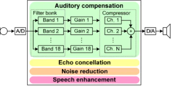
NTRODUCTIONThe small dimension of hearing aids severely limits the sizes of electronic devices and battery (thus the power consumption of the devices). Hence, designers must try their best to reduce the algorithmic complexity first to meet the crucial area and power constraints. Fig. 1 depicts a generic digital hearing aid, including functional blocks such as auditory compensation, echo (feedback) cancellation, noise reduction/suppression, and speech enhancement, etc. Auditory compensation is the main function in hearing aids, which performs frequency shaping to compensate the hearing loss. A filter bank decomposes the input signal into different frequency bands so that the prescribed gains can be applied on each band. A compressor then compresses dynamic ranges of the compensated signals to fit the diminished dynamic range of the hearing impaired.
… … …
Figure 1. Digital hearing aid
A fitting procedure calculates the individual gains to be applied on each band, and most fitting procedures (e.g. NAL-NL1 [1][2]) are based on 1/3-octave bands. ANSI S1.11 standard [3] defines the
specification for the octave and fractional-octave band filters for acoustics applications. However, most hearing aids use proprietary filter banks instead to reduce the implementation complexity [4][5], which do not comply with the ANSI S1.11 standard. By the way, existing ANSI S1.11 implementations [6][7], to our knowledge, are all based on IIR filters, even in applications with more budgets on silicon area and power consumption. Unfortunately, linear phase is essential in feedback cancellation [4], which is another important building block in digital hearing aids. In other words, IIR is not feasible. Therefore, a low-complexity FIR filter bank that complies with the ANSI S1.11 standard is desired for digital hearing aids. In this paper, we propose a multi-rate FIR filter bank to minimize data rates of the bandwidth-limited bands. We also propose a systematic method to synthesize the minimal FIR coefficients for the multi-rate filter bank.
The rest of this paper is organized as follows. Section 2 describes the 1/3-octave bands briefly and reviews the ANSI S1.11 specification. Section 3 shows the adopted multi-rate architecture for the 1/3-octave filter bank and our proposed flow for the design and optimization of the FIR coefficients thereof. The comparisons of the computational complexity and the filter response of our proposed approach are summarized in Section 4. Finally, Section 5 concludes this paper and outlines our future researches.
II. ANSI
S1.11
S
PECIFICATIONANSI S1.11 provides the performance specification for the octave and fractional-octave-band filter bank. This section would briefly describe the definition of the 1/3-octave bands and the performance requirement of ANSI S1.11 filter banks.
A. 1/3-octave Bands
ANSI standard defines 43 1/3-octave bands in the frequency range of 0~20 KHz. Each band’s location and range is specified by its mid-band frequency and bandwidth. The mid-band frequency of the xth band f m(x) is defined as
( )
( ) r x m x f f = −3 × 30 2,
where fr is the reference frequency set as 1,000 Hz in the standard.
For example, the mid-band frequency of the 29th band f
m(29) is 794
( 2( 3 ) 1,000 30 29
×
= − ), and the mid-band frequency of the 31st band f m(31)
is 1,260 ( 2( 3 ) 1,000 30 31
×
= − ). Besides, the standard defines each band’s lower (f1) and upper (f2) band-edge frequencies as
6 1 1 2 − × = fm f
,
6 1 2= fm×2 fThe bandwidth is defined as the frequencies between f1 and f2. For
instance, the bandwidth of the 30th band is from 891 Hz to 1,112 Hz.
B. Performance Requirement
ANSI S1.11 standard describes the specifications of the filter’s relative attenuation, integrated filter response, environment sensitivity (e.g. humidity, electromagnetic field, and temperature), maximum output signal, terminating impedance and some other parameters for three filter classes, that is, class-0, 1, and 2. The specification of the relative attenuation for class-2 filters is shown in Fig. 2, where the green and red curves respectively represent the limits on the maximum and the minimum attenuations. Fig 2 shows that a class-2 filter allows a 1 dB ripple in its passband region (i.e. f1
~ f2) and has a 60 dB attenuation at frequencies small than f1’ (= fm ×
0.184) and at frequencies greater than f2’ (= fm × 5.434). The
specifications of class-0 and class-1 filters are stricter than that of 2 filters. For example, the maximum passband ripple of class-1 filters is 0.6 dB. This paper design an class-18-band filter bank for the 22nd ~ 39th band (covering the frequency from 140 Hz to 8980 Hz)
with the class-2 specifications.
Figure 2. ANSI S1.11 class-2 filter specification
III. P
ROPOSEDA
RCHITECTURE ANDF
ILTERD
ESIGNIn this section, we describe the 1/3-octave filter bank design that comply with the ANSI S1.11 class-2 specification for a digital hearing aid with 18-band auditory compensation [9].
A. Filter Bank Architecture
Fig. 3 shows the proposed multi-rate architecture of the 18-band filter bank, where the symbol X and Y denote the input and output of the auditory compensation respectively. The multi-rate filter bank only implements the highest octave’s three filters (i.e. F37, F38
and F39) and a decimation filter (denoted by D). In the rest of this
paper, we use the notation Fn to represent the filter of the nth band.
Figure 3. Proposed filter bank architecture
According to the 1/3-octave definition, each octave (i.e. three 1/3-octave bands) has the identical frequency characteristics if the sampling rate is reduced by 2 for every octave. For example, the characteristics of the 36th band are the same as that of the 39th band
if its sampling rate is half of that of the 39th band. Therefore, our
multi-rate filter bank could iteratively calculate the lower octaves with F37 ~ F39, when the input signal is band-limited by D and
down-sampled by 2 for each octave, as shown in Fig. 3. This implies that we need not to design extremely narrow-band filters (which require high-order FIR) for the lowest octave bands
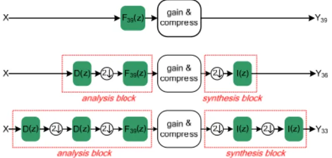
The proposed multi-rate filter bank minimizes the sampling rate of the band-limited channels to reduce the computation complexity of the filter bank and the compressor. However, a synthesis block is required to up-sample those channels before output. The equivalent datapaths for the 39th, 36th, and 33rd bands is depicted in Fig. 4,
where the symbol I denotes the interpolation filter and Yn denotes
the nth band’s output. The sampling rate of the compression block
is reduced to the half in the 36th band, and one fourth in the 33rd
band. Besides, the signal in the 39th band is also band-limited by
F39 such that the compression of the 39th band could operate at a
lower sampling rate. Hence, there might be additional decimators in the compression block to further reduce the sampling rate. However, we focus our discussion on the filter bank and the details of the compressor are beyond this paper’s scope.
Figure 4. Datapath of the 39th, 36th and 33rd bands
To derive each band’s response, we first remove the gain & compress block from the datapath for simplicity. The simplified datapath of the 36th band is shown in Fig. 5(a), where we could
exploit the noble identity [8] such that F39 is moved to the front of
the decimator, as shown in Fig. 5(b).
Figure 5. (a) Simplfied datapath of the 36th band, (b) noble identity
The multi-rate processing in Fig. 5(b), that is, the function of
D(z), down-sampled by2, up-sampled by 2, and I(z) is described as
) ( ) ( ) ( 2 1 ) ( ) ( ) ( 2 1 z I z D z X z I z D z X ⋅ ⋅ + − ⋅ − ⋅ [8]. Therefore, we could write the equation of Yn (n = 22 ~ 36) as
( )
[
( )
( )
( ) ( )
]
( )
( )
( ) ( )
[
X z F z D z I z]
z I z D z F z X z Y n n n ⋅ − ⋅ ⋅ − + ⋅ ⋅ ⋅ = + + 2 3 2 3 2 1 2 1 (1)B. Filter Design
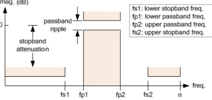
The FIR coefficients are designed using MATLAB firpm and firmpord functions. firpmord uses the parameters shown in Fig. 6 to generate the required inputs (such as filter order) for firpm, which then uses the results of firmpord to produce the filter coefficients. In other words, we need to find out the optimal values of the parameters (i.e. fs1, fp1, fp2 and fs2) in Fig. 6 for F37,
F38, F39, D and I respectively. Note that only one passband
frequency and one stopband frequency need to be specified when we design low-pass filters.
Figure 6. Paramters of the firmpord function in MATLAB The filter design problem for the multi-rate filter banks is to find the coefficients of F37, F38, F39, D and I, so that F22 ~ F39 meet
ANSI S1.11 class-2 specification and the overall computational complexity is minimized. A filter design flow that contains two steps is proposed. The following will describe the details of our filter design flow.
Step 1: Design F37 ~ F 39 and D/I independently
We first design F37 ~ F39 such that the specifications of the
37th~39th bands are met and the orders are minimized. Following
the ANSI S1.11 class-2 specification shown in Fig. 2, the passband ripple and stopband attenuation of F37 ~ F39 are set as 1 and 60 dB
respectively. In other words, we need to find out the optimal values of fs1, fp1, fp2 and fs2 for F37 ~ F39. Since the orders of the
designed filters are dominated by the filters’ transition bandwidths, the problem of finding fs1, fp1, fp2 and fs2 is then translated into finding the transition bandwidths (denoted as TBW1 and TBW2),
fs1 and fs2, where TBW1 = fp1 – fs1 and TBW2 = fs2 – fp2.
Besides, to simplify the design process, we decompose the band-pass filter specifications of F37 ~ F39 into a low-pass and a high-pass
specifications and find the range of TBW1 and TBW2 separately. That is, we try to design a high-pass filter satisfying the high-pass specification with the transition bandwidth = TBW1, and a low-pas filter satisfying the low-pass specification with the transition bandwidth = TBW2. The range of TBW is determined as following: we first find the widest TBW (with which the designed filter could satisfy the high-pass/low-pass specification) and its corresponding order (denoted as ord_min), then we find the narrowest TBW with comparable order (i.e. order < ord_min×1.1). We then check the feasibility of the TBW pairs (i.e. verify that the band-pass filter design with certain TBW pair could meet the specification) and
select the best results among those feasible TBW pairs. In this step,
F37, F38 and F39 are designed as 40-tap, 33-tap, and 25-tap filters,
respectively.
Secondly, we design D and I assuming that the magnitude of
F37 ~ F39 is 0 dB for frequencies between f1 and f2 (which are
defined in Section 2), while the magnitude is -60 dB for other frequencies. Under this assumption, the attenuation of F22 ~ F35
would meet the specifications as long as F36 meets (but not
including ripple). Therefore, we consider the equation of Y36, which
can be find in (1) with n = 36. We ignores the scalar constant 1/2 and assume the aliasing term X(-z) is to be suppressed; thus the response of F36 is F39(z2)·D(z)·I(z). That is, D(z)I(z) should be a
low-pass filter which suppresses the image in F39(z2) and D(z)I(z)’s
ripple should be small enough so that the ripples of F22 ~ F36 are
within 1 dB. Besides, D(-z)I(z) should be an all-reject filter to suppressing the aliasing term X(-z) and we assume the magnitude of
D(-z)I(z) should be smaller than -60dB. From above discussions,
we design D and I as following. For D(z)I(z) suppressing the image in F39(z2), we set D and I’s stopband frequency = 0.628π and
passband frequency = 0.374π (to cover the passband of F36), as
shown in Fig. 7. For D(-z)I(z) suppressing X(-z) to -60dB, we set D and I’s stopband attenuation = -60 dB, and we gradually decreased the stopband frequency (starting from 0.628π) until the magnitude of D(-z)I(z) is smaller than -60 dB. Finally, the ripple of D and I is successively reduced until the ripples of F22 ~ F36 are within 1 dB.
This procedure leads to a 29-tap filter for D and a 34-tap filter for I.
0 0.2 0.4 0.6 0.8 1 -60 -50 -40 -30 -20 -10 0
Figure 7. F39(z2) and the specification of the 36th band
TABLE I FINE-TUNING RESULT
ripple (dB) # taps complexity F37~39 D/I F37 F38 F39 D I # mpy # add
0.0 0.40 - - - 29 34 NA NA 0.1 0.20 57 46 36 32 37 206 398 0.2 0.30 56 45 36 32 37 204 394 0.3 0.10 53 44 33 35 41 206 393 0.4 0.30 52 41 33 32 37 194 372 0.5 0.10 52 41 33 35 41 202 386 0.6 0.10 48 38 33 35 41 194 372 0.7 0.10 47 37 30 35 41 190 362 0.8 0.10 42 33 26 35 41 176 336 0.9 0.10 41 33 26 35 41 176 334 1.0 0.02 40 33 25 41 48 186 356 Step 2: Fine tuning
The ripple caused by D(z)I(z) plus the ripple of F37 ~ F39 could
make the response of F22 ~ F36 out of specifications. Therefore, the
filters need to be fine-tuned for the overall ripple. Since D and I are designed assuming F37 ~ F39 has ripple = 0 dB. Here we gradually
increase the ripple of F37 ~ F39 and find out how small the ripple of
D and I should be to make F22 ~ F36 meet the specifications. We
design F37 ~ F39 with ripple =0.1~ 1 dB and choose the best one.
The results and the computations per sample are shown in Table I.
IV. R
ESULTSA. Computational Complexity
To demonstrate the effectiveness of the multi-rate architecture and our proposed FIR optimizations, we have designed the parallel and the multi-rate FIR banks respectively for the 22nd ~ 39th band in
ANSI 1/3-octave bands. We have also designed the parallel [9] and the multi-rate IIR [6] banks for comparison. The ANSI S1.11 implementations in the literatures [6][7][9] all adopted Butterworth IIR. In general, Elliptic IIR has smaller orders but the difference is small since the orders are both quite small. Thus, Butterworth is also used in this comparison. The input sampling rate is 24 kHz, which covers the 39th band. All filter coefficients are generated
using the MATLAB (version 7.2) filter design toolbox. Table II summarizes the numbers of multiplications and additions for a single input sample. For parallel structure, the FIR bank requires filters of order 25 ~ 1,488, while the IIR one uses 8th-order
Butterworth for F39 and 6th-order Butterworth for F38 ~ F22 (Fn
denotes the filter of the nth band). Therefore, the parallel FIR bank
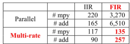
requires 3,270 multiplications (coefficient symmetry is exploited) and the parallel IIR bank requires 220 multiplications. In other words, the parallel FIR bank needs 14.8 times more multiplications than the IIR one. On the other hand, the multi-rate FIR bank implements 26/33/40-tap FIR filters F37 ~ F39 respectively, and a
35-tap FIR filter for decimation. Thus, an input sample requires 135 multiplications and 257 additions respectively, which saves 96% computations in the parallel FIR bank. Note that the multi-rate architecture reduces the computation of the parallel IIR bank as well. However, the reduction is not as significant as the FIR bank and thus the multi-rate FIR bank has comparable complexity with the multi-rate IIR bank.
TABLE II COMPLEXITY COMPARISON
IIR FIR # mpy 220 3,270 Parallel # add 165 6,510 # mpy 117 135 Multi-rate # add 90 257
B. Filter Response
Fig. 8 shows the response of the 22nd band for the four filter
banks. The ANSI S1.11 class-2 specifications are also plotted (the red and the green curves) to demonstrate the filter banks comply with the standard. We can see that the FIR bank adopts the equal ripple design, which requires a sharper slope in transition to meet the specification, while the response of IIR bank is smoother. Besides, an image component (the circled) is present in the response of multi-rate filters banks, as that we discussed in Section 3. The passband ripple of the multi-rate filter banks is slightly greater than that of the parallel filter banks; the reason is both the decimation and interpolation filters may add additional ripples to the response.
0 0.01 0.02 0.03 0.04 0.05 -60 -40 -20 0 normilized frequency(pi) m agni tu de( dB ) 0 0.01 0.02 0.03 0.04 0.05 -60 -40 -20 0 normilized frequency(pi) m agni tude( dB ) 0 0.01 0.02 0.03 0.04 0.05 -60 -40 -20 0 normilized frequency(pi) m agn itude (dB ) 0 0.01 0.02 0.03 0.04 0.05 -60 -40 -20 0 normilized frequency(pi) m agn itude (dB ) 0.01 0.017 -14 0 0.01 0.017 -14 0 0.01 0.017 -14 0 0.01 0.017 -14 0
Figure 8. Response of the 22nd band in (a) parallel IIR bank (b) parallel FIR bank (c) multi-rate IIR bank and (d) multi-rate FIR bank
V. C
ONCLUSIONIn this paper, we propose a multi-rate architecture to implement the ANSI S1.11 filter bank with FIR filters for digital hearing aids, where the computations can be greatly reduced with the multi-rate processing. We also propose a systematic flow to optimize the FIR coefficients for the multi-rate filter banks to minimize their orders. Our design saves 96% multiplications and additions of a parallel FIR bank. By the way, multi-rate processing can be applied on the IIR filter bank as well. However, the complexity reduction is not as significant as that of FIR banks. In brief, our multi-rate FIR bank has linear-phase property and also has comparable complexity with IIR banks. In the future, we will study the fixed-point coefficients with numerical optimizations to further reduce the implementation complexity of the FIR banks.
R
EFERENCES[1] H. Dillon, Hearing Aids, Thieme Medical Publisher, 2001 [2] M. S. Ho and S. T. Young, “Building a platform of hearing aid’s
compensative strategy for Mandarin,” in Proc. International
Congress on Acoustics, 2004
[3] Specification for Octave-band and Fractional-octave-band Analog
and Digital Filters, ANSI S1.11-2004, Feb. 2004, Standards
Secretariat Acoustical Society of America
[4] K. S. Chong, B. H. Gwee and J. S. Chang, “A 16-channel low-power nonuniform spaced filter bank core for digital hearing aid,” IEEE
Trans. Circuits Syst. II, Exp. Briefs, vol. 53, Sept. 2006
[5] Y. Lian and Y. Wei, “A computationally efficient nonuniform FIR digital filter bank for hearing aids,” IEEE Trans. Circuits Syst. I, Reg.
Papers, vol. 52, Dec. 2005
[6] A. Lozano and A. Carlosena, “DSP-based implementation of an ANSI S1.11 acoustic analyzer,” IEEE Trans. Instrum. Meas., vol. 52, Aug. 2003
[7] J. W. Waite, “A multirate bank of digital bandpass filters for acoustic applications – design of HP’s 3569A real-time frequency analyzer,”
Hewlett-Packard Journal, Apr. 1993
[8] P. P. Vaidyanathan, Multirate Systems and Filter Banks, Prentice Hall, 1993
[9] P. Y. Lin, Feasibility Study of the Implementation of Hearing Aid
Signal Processing Algorithms on the TI TMS320C6713 DSK, Master
thesis, Institute of Biomedical Engineering, National Yang Ming University, 2004