i
國立交通大學
光電工程研究所
博士論文
利用即時側向繞射位置監控及紫外光
接續寫入法製作布拉格光纖光柵
Fiber Bragg Grating Sequential UV-Writing
with Real-Time Interferometric Side-Diffraction
Position Monitoring
研究生:徐桂珠
指導教授:賴暎杰
ii
利用即時側向繞射位置監控及紫外光接續寫入法
製作布拉格光纖光柵
Fiber Bragg Grating Sequential UV-Writing with Real-Time
Interferometric Side-Diffraction Position Monitoring
研 究 生:徐桂珠 Student:Kuei-Chu Hsu
指導教授:賴暎杰 博士 Advisor:Yinchieh Lai
國 立 交 通 大 學
光 電 工 程 研 究 所
博 士 論 文
A DissertationSubmitted to Department of Photonics and Institute of Electro-Optical Engineering College of Electrical Engineering and Computer Science
National Chiao Tung University in Partial Fulfillment of the Requirements
for the Degree of Doctor of Philosophy in
Electro-Optical Engineering June 2007
Hsinchu, Taiwan, Republic of China
iii 利用即時側向繞射位置監控及紫外光接續寫入法製作布拉格光纖光柵 國立交通大學 光電工程研究所 學生:徐桂珠 指導教授:賴暎杰博士
摘要
在本論文中我們首度發展出在紫外光接續寫入布拉格光纖光柵過程中的 新型即時光纖位置監控方法,為了即時對準待曝照的次光柵位置,我們使用側 向繞射法來偵測另一個單一週期的光纖光柵之相位作為位置的參考點,如此可 以較不受量測飄移的影響。 在本研究中我們也仔細校正了紫外光曝光量與光纖引致的折射率變化量之非 線性關係圖,經由事先作紫外光處理,可以避免在紫外光量微弱時,因光纖的折 射率變化量對紫外光強度呈非線性曲線而造成誤差。我們也發展出使用光強度不 相同的新型雙光束干涉法來達到在單次寫入光纖過程中,從而可以保持光纖折射 率變化與寫入的紫外光量成正比。 我們也提出一個簡單的方法來達到光纖光柵平均折射率維持定值而折射率調 變形狀可加以控制的光纖光柵製造方法。此方法在每一個欲寫入次光柵的位置, 將紫外光待曝光量分成前後兩次曝照,而折射率調變的形狀可藉由控制前後寫入 兩紫外光的相對相位和強度來調整,如此沿著整個光纖光柵的平均折射率都保持 固定值,而局部調整折射率調變的形狀卻可以任意控制。 整體而言,藉著我們發展出的這套光纖光柵製作技術可以建造一個精良的光 纖光柵製作平台,從而可以針對不同應用製造出複雜的光纖光柵。iv
Fiber Bragg Grating Sequential UV-Writing with Real-Time
Interferometric Side-Diffraction Position Monitoring
Department of Photonics and the Institute of Electro-Optical Engineering National Chiao Tung University
Student:Kuei-Chu Hsu Advisor:Prof. Yinchieh Lai
ABSTRACT
In this dissertation we develop a new real-time fiber position monitoring method for fiber Bragg grating (FBG) sequential UV-writing processes. To real-time accurately align the position of every exposed FBG, a single-period reference fiber grating is probed by applying an interferometric side-diffraction method to measure the grating phase as the position reference, so that the writing process can be less sensitive to the measurement drifts.
During the research we have also calibrated carefully the nonlinear relationship between the UV flux and the induced index change. The pre UV treatment method can avoid the nonlinear index change response regime when the UV flux is low. An improved unequal-intensity UV two-beam interference scheme is proposed and demonstrated to achieve the index response linearization in a single scan.
Finally, a simple method for attaining pure apodization of FBGs has also been proposed. The UV exposure at every exposed location is achieved in two exposure steps and the ac index modulation is adjusted by controlling the superimposed phase and amplitude of the two imprinted UV fringes. The average refractive index is kept constant, and the ac index modulation can be locally and independently changed.
Based on the grating inscription skills, we have developed an excellent grating fabrication platform to produce complex FBGs for various applications.
v
ACKNOWLEDGEMENT
我的指導教授,賴暎杰博士,是我在交大的這五年日子裡最重要的人。我會 永遠記得賴老師是怎樣期許我往一個真正學者的路邁進。未來的日子裡我未必有 他的智慧和能力,但我會學習他的堅持和風範。想起「倚天屠龍記」裡張翠山對 恩師張三丰的不勝仰慕欽敬之情,「夫千里之遠,不足以舉其大,千仞之高,不足 以極其深。」。這句話也正是我對賴老師崇仰之心的寫照。 很難忘2005 年在德國作交換學生那個燦爛的夏天。和六位同行的可愛伙伴遊 遍德國城市鄉間;在 Jena 小鎮結識親切的陳啟昌老師更是一段很特別的回憶。 2006 年到美國亞利桑納大學作為訪問學者的經驗,在各方面的見識都大為增長。 亞利桑納大學光學中心裡開放的風氣和優良的學風、學者對學術研究充滿熱忱和 全心投入的態度、以及克服一個人在異國生活的種種問題,這些都令我短時間內 快速的成長。 交大親友團是我這些年來最大的支柱。許立根學長、陳南光、莊凱評、項維 巍、李瑞光及李澄鈴學姊,謝謝你們的專業支持及同門情誼。Kate、森益、至賢、 同慶、明芳、鴻章、仁宇、企桓、建舜、晴如、淑惠、鐘响、人豪、柜峰、倩伃、 翔榮、鼎鈞、萓蘘、金廠、欣哲、宥涵、佩蓁、宸瑋、宏傑、智明、聖龍、芙涵、 室友淑婷,謝謝你們溫暖的友誼。這些年來許多的歡喜和悲傷,沒有你們我絕對 撐不下去。特別還要感謝葉李華老師,他作學問的投入態度和創意科學方法,以 及對後進不吝鼓勵提攜的熱情,這樣的大師風範,對我的思考和人生觀產生深遠 的影響。 謝謝家人無盡的支持。 深深感謝許多人一路走來給我的支持和幫助。我也期許自己,將來一定繼續 在專業領域上求進步,以求不辜負大家的期望,也不能辜負自己的期望。 謹將這本論文獻給我在天上的母親。vi
CONTENTS
Page
Abstract (in Chinese)
iiiAbstract (in English)
ivAcknowledgement
vContents
viList of Figures
viiiChapter 1 :
Introduction 11.1 Review of Fiber Bragg Grating Devices and Lightwave Applications
1
1.2 Motivation 3
1.3 Organization of the Dissertation 4
1.4 References 4
Chapter 2 :
Fiber Bragg Grating Model and Fabrication Method 82.1 Introduction 8
2.2 Theory of FBG Filters 8
2.2-1 Fundamental Properties of FBG Filters 9 2.2-2 Mathematical Model of FBG Filters 9 2.3 Photosensitivity in Optical Fibers 11
2.3-1 Photosensitivity Mechanisms in Germanium-Doped Silica Fibers
12 2.3-2 Photosensitivity in Germanium-Boron Codoped
Silicate Fibers
13 2.4 Fiber Bragg Grating Fabrication 13
2.4-1 FBG Fabrication Using Phase-Mask and Two Beam Interference Technique
13 2.4-2 Long FBG Fabrication Using Scanning Fiber/Light
Source and Sequential Writing Method
14 2.4-3 Apodization of FBG Index Profile 15
2.5 References 17
Chapter 3 :
Fiber Bragg Grating Fabrication by Interferometric Side-Diffraction Position Monitoring Scheme23
3.1 Narrow Band FBGs 23
3.2 Interferometric Side Diffraction Method 24 3.3 Fiber Bragg Grating Fabrication by Interferometric 26
vii
Side-Diffraction Position Monitoring
3.3-1 Fiber Bragg Grating Fabrication by Interferometric Side-Diffraction Position Monitoring with Exposed Fiber Section
27
3.3-2 Fiber Bragg Grating Fabrication by Interferometric Side-Diffraction Position Monitoring with Reference Fiber Grating
30
3.4 Summary 32
3.5 References 32
Chapter 4 :
Methods of Achieving Linear Index-Change Response for Narrow-Band Fiber Bragg Grating Sequential Writing43
4.1 Introduction 43
4.2 Nonlinear Photosensitivity and Pre UV Treatment 44 4.3 Unequal Two Beam Interference Setup for Achieving Linear
Index Response
47
4.4 Summary 49
4.5 References 49
Chapter 5 :
Simple Pure Apodization Method for Fiber Bragg Gratings by Sequential UV Writing56
5.1 Introduction 56
5.2 Theory and Experiment 57
5.3 Summary 60
5.4 References 61
Chapter 6
: Conclusions and Future Work 686.1 Conclusions 68 6.1 Future Work 70 6.2-1 Complex FBG Fabrication 70 6.2-2 FBG Sensor Applications 71 6.2-3 FBGs in Fiber Lasers 71 6.3 References 72 Vita 73 Publication List 74
viii
LIST OF FIGURES
Fig. 1.1 Fiber Bragg grating structure...7 Fig. 2.1 (a) Uniform grating index profile and spectrum. RIM: refractive
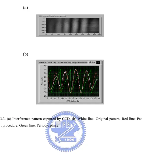
index modulation. (b) Apodized grating index profile and spectrum. (c) Pure apodized grating index profile and spectrum...21 Fig. 2.2 (a) Pure apodization setup. M: Mirror, HWP: half wave plate,
BS: beam splitter, A: arm A, B: arm B. (b) Sequential writing with constant average refractive index along the entire grating length... ...22 Fig. 3.1 Experimental setup of side-diffraction method. HWP: half wave
plate, PBS: polarization beam splitter... ...36 Fig. 3.2 (a) Real-time side-diffraction position monitoring setup by
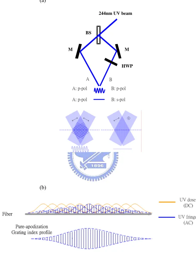
probing the just-exposed section. SL: spherical lens; BC: beam combiner; PBS: polarization beam splitter; HWP: half wave plate. (b) Typical interference pattern captured by CCD, the pattern after procedure (filtering+taking-real-part) and the calculated phase distribution.. ...37 Fig. 3.3 (a) Interference pattern captured by CCD. (b) White line:
Original pattern, Red line: Pattern after , procedure, Green line: Periodic phase... ...38 Fig. 3.4 Refractive index profile and Bragg wavelength of a uniform
fiber grating...39 Fig. 3.5 (a) Real-time side-diffraction position monitoring setup by
probing the reference grating. (b) Flow chart of the algorithm.. ...40 Fig. 3.6 (a) Illustration of side-diffraction interferometric position
monitoring method to fabricate Gaussian apodized FBG. (b) Illustration of side-diffraction interferometric position
ix
monitoring method to fabricate phase-shifted Gaussian apodized FBG. ...41 Fig. 3.7 (a) Reflection and transmission spectra of a 0.07-nm Gaussian
apodized 70-mm long FBG. (b) Reflection and transmission spectra of a 40-mm long, π-phase-shift Gaussian apodized FBG. .
...42 Fig. 4.1 (a) Refractive index modulation profile of a single Gaussian shot
UV writing with specific UV flux. (b) Refractive index modulation versus UV exposure flux. . ...52 Fig. 4.2 (a) Refractive index modulation profiles with pre UV treatment
of a single Gaussian shot UV writing with specific UV flux. (b) Refractive index modulation versus UV exposure flux with pre UV treatment. . ...53 Fig. 4.3 (a) Experimental setup of unequal-intensity two beam
interference. The intensity ratio of beam A and beam B is 0.45. (b). Illustration of UV flux variation versus grating length with unequal-intensity two beam interference setup. ...54 Fig. 4.4 (a) Refractive index modulation profiles for experimental and
target gratings with unequal-intensity two beam UV writing. (b) Reflection and transmission spectrum of the grating with unequal-intensity two beam UV writing.. ...55
Fig. 5.1 (a) Schematic of UV sequential writing. (b) Superposed UV fringe by controlling intensities and phases of the two sequentially writing shots.. . . ...63 Fig. 5.2 Index profiles of single grating section utilized (a) configuration
1 and (b) configuration 2. Experimental and simulation of index modulation of single grating section utilized (c) configuration 1 and (d) configuration 2.. . ...64 Fig. 5.3 Connected FBG index profile utilized (a) configuration 1 and (b)
x
spectrum utilized (c) configuration 1and (d) configuration 2. . . ....65 Table 5.1 The conditions of the two configurations. . . ...66 Table 5.2 Simulation of how random position error contributes to
transmission and sidelobe suppression ratio in one shot case and two configurations. . . ...67
1
Chapter 1
Introduction
1.1
Review of Fiber Bragg Grating Devices and
Lightwave Applications
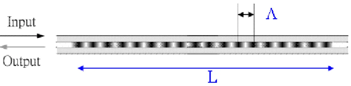
The fiber Bragg grating (FBG) research can be dating back to Ken Hill in 1978 [1.1], and during the past few years the research publications in this area still widely appear in international journals and conferences. FBGs are reflective type filters with periodic refractive index modulation running along fiber axis in the fiber core, as shown in Fig. 1.1. Incident wavelengths are reflected when the Bragg condition is satisfied, and otherwise they are transmitted. Owning to all-fiber geometry and low insertion loss, FBGs are critical components in some fiber-optic communication and fiber sensor applications. Today commercial FBG manufacturing technology is already quite matured. The typical grating period is around 535 nm when the reflection center wavelength is located at 1550 nm for optical communication window, and the typical reflectivity is 99.99 %. The center wavelength can be fine-tuned by adding stress on the grating to change its period. Environmental stability was originally a big issue but can be controlled now by suitable annealing process and appropriate package.
FBGs are usually fabricated by imprinting the periodical intensity of UV lights onto the fiber core to induce the periodical refractive index change. The photosensitivity of the core of optical fibers is caused by the fact that the Ge and Si atom bond has the absorption peak around 244 nm. On UV illumination, the bond readily breaks, creating the defect centers that cause refractive index change. Several laser sources with different photosensitive mechanisms are utilized in the literature to
2
induce periodic refractive index changes inside the fiber. Several fabrication schemes have also been proposed for FBG inscription by forming interference light fringes, including the holographic method and phase mask method. The former is flexible for adjustable Bragg wavelength by changing the two beam interfered angle, while the latter is more insensitive to the environmental variation. In this dissertation, our FBG fabrication process adopts the holographic writing scheme and utilizes 244-nm-UV radiation to induce changes in refractive index.
Besides the optical filtering applications in optic communication, numerous other applications of FBG devices provide a platform for researchers in different optical areas. Several important applications of FBGs are in temperature and strain sensing [1.2], feedback mirror in fiber lasers [1.3], and odd-drop mutiplexers as well as dispersion compensator in optical communication systems [1.4]. The FBG sensors rely on Bragg wavelength shift corresponding to environmental perturbations of strain and temperature. FBGs as feedback mirrors in fiber laser cavities are highly developed recently. Narrow-band FBGs at two ends of rare-earth-doped fibers formed Fabry-Perot laser cavities as DFB (distributed feedback) lasers that support single-longitudinal mode operation. DBR (distributed Bragg reflector) fiber laser is obtained by putting a phase-shifted grating on the rare-earth-doped fibers, so that the grating is treated as a narrow-band transmission filter. Furthermore, the gain-flatten function makes fiber gratings hot devices in fiber amplifiers systems. Many efforts have been made to improve the fiber laser power and output performance by directly writing FBGs on rare-earth-doped fiber and photonic crystal fibers recently [1.5-1.7]. Therefore designing and fabricating state-of-the-art FBGs is promising and very useful in various photonic industries.
3
1.2 Motivation
Advanced fiber gratings have found many applications in various optical areas. Among them, narrow-band FBG devices are important elements for high demanding DWDM and Optical Add/Drop Multiplexer systems as well as in fiber laser systems. Narrow-band FBGs possess long-length and weak refractive index change in optical fibers. Manufacturing such long-length fiber gratings by adopting the phase mask and holographic schemes are limited by the phase mask length or environmental fluctuations respectively.
Our group started the art of FBG design and production in the recent few years and already had achieved some good results in this area [1.8-1.16]. Establishing the easy-realized FBGs technology is our long-term aim of project development. The purpose of this dissertation is to develop a state-of-the-art technique to fabricate narrow-band FBGs with the potential of applying various designs of grating structures. We adopted the side-diffraction method which was originally used for measuring fiber grating index profile and modified the setup to real-time monitor the fiber position during the grating written process. The UV flux and refractive index change profile is further studied to carefully calibrate the photosensitivity relationship curve. Besides, a simple UV exposure method is proposed to achieve pure apodization for fiber Bragg gratings fabricated by sequential UV writing. We believe the fabrication improvement and the calibration results are quite useful in advanced fiber grating fabrication.
To summarize, in this dissertation we have proposed and demonstrated several methods for achieving FBG pure apodization, long-length grating with sequential UV writing, and better linear index response. An advanced FBG fabrication platform is also established based on these methods.
4
1.3 Organization of the Dissertation
This dissertation consists of six chapters. In Chapter 1, the development and application of FBG devices are described. In Chapter 2, the fundamental properties, the photosensitivity of germanium doped silica fibers, and fabrication technology of FBG devices are recounted. In Chapter 3, the proposed real-time side-diffraction position monitoring scheme has been demonstrated to fabricate long-length fiber Bragg gratings. To real-time accurately align the position of every exposed FBG section prior to UV exposure, a single-period reference fiber grating with strong refractive index modulation is probed by applying an interferometric side-diffraction method to measure the grating phase as the position reference. In Chapter 4, the correlation of UV flux and refractive index change of optical fibers is investigated. The pre UV treatment method and unequal two beam interference method are proposed to achieve linear index response of written gratings. In Chapter 5, a simple pure apodization method is proposed. Through the exposure phase and/or time control of multiple UV shots, the ac-index can be adjusted independently with the dc-index kept constant. The conclusions and suggested future works are given in Chapter 6.
1.4 References
[1.1] Hill K. O., Fujii Y., Johnson D. C., and Kawasaki B. S., “Photosensitivity in optical waveguides: Application to reflection filter fabrication,” Appl. Phys. Lett. 32, 647-649 (1978).
[1.2] A. D. Kersey, M. A. Davis, H. J. Patrick, M. LeBlanc, K. P. Koo, C. G. Askins, M. A. Putnam, and E. J. Friebele, “Fiber grating sensors,” J. Lightwave Technol. 15, 1442–1450 (1997).
5
Lightwave Technol. 15, 1378–1384 (1997).
[1.4] C. R. Giles, “Lightwave applications of fiber Bragg gratings,” J. Lightwave Technol. 15, 1391–1400 (1997).
[1.5] A. Martinez, I. Khrushchev, and I. Bennion, “Direct inscription of Bragg gratings in coated fibers by an infrared femtosecond laser,” Opt. Lett. 31, 1603-1605 (2006).
[1.6] E. Wikszak, J. Thomas, J. Burghoff, B. Ortac, J. Limpert, S. Nolte, U. Fuchs, and A. Tuennermann, “Erbium fiber laser based on intracore femtosecond-written fiber Bragg grating,” Opt. Lett. 31, 2390-2392 (2006). [1.7] J. Albert, A. Schülzgen, V/ L. Temyanko, S. Honkanen, and N. Peyghambarian,
“Strong Bragg gratings in phosphate glass single mode fiber,” Appl. Phys. Lett.
89, 101127 (2006).
[1.8] C.-L. Lee and Y. Lai, “Evolutionary Programming Synthesis of Optimal Long-Period Fiber Grating Filters for EDFA Gain-Flattening,” IEEE Photon. Tech. Lett. 14, 1557-1559 (2002).
[1.9] L.-G. Sheu, K.-P. Chuang, and Y. Lai, “Fiber Bragg grating dispersion compensator by single-period overlap-step-scan exposure”, IEEE Photon. Tech. Lett. 15, 1557-1559 (2003).
[1.10] C.-L. Lee and Y. Lai, “Synthesis of long-period fiber gratings using evolutionary programming”, Fiber & Integrated Optics 23, 249-261 (2004). [1.11] K.-P. Chuang, L.-G. Sheu, and Y. Lai, “Pure apodized phase-shifted fiber Bragg
gratings fabricated by a two-beam interferometer with polarization control”, IEEE Photon. Technol. Lett. 16, 834-836 (2004).
[1.12] K.-P. Chuang, L.-G. Sheu, and Y. Lai, “Complex fiber grating structures fabricated by sequential writing with polarization control”, Opt. Lett. 29,
6
340-342 (2004).
[1.13] C.-L. Lee and Y. Lai, “Optimal dispersionless fiber Bragg grating filter with shorter grating length and smoother dispersion profile”, Opt. Comm. 235, 99-106 (2004).
[1.14] Kuei-Chu Hsu, Lih-Gen Sheu, Kai-Ping Chuang, Shu-Hui Chang and Yinchieh Lai, “Fiber Bragg grating sequential UV-writing method with real-time interferometric side-diffraction position monitoring,” Opt. Express 13, 3795-3801 (2005).
[1.15] Cheng-Ling Lee, Ray-Kuang Lee, Yee-Mou Kao, “Design of multichannel DWDM fiber Bragg grating filters by Lagrange multiplier constrained optimization,” Opt. Express 14, 11002-11011 (2006).
[1.16] Kuei-Chu Hsu, Lih-Gen Sheu, Wei-Wei-Hsiang, and Yinchieh Lai, “Methods of achieving linear index-change response for narrow-band fiber Bragg grating sequential writing,” accepted by Opt. Commun.
7
8
Chapter 2
Fiber Bragg Grating Model and Fabrication
Method
2.1 Introduction
The reflection spectrum of the FBG filter and its periodic index profile are Fourier transform pairs in the low index change limit. Getting deeper understanding between the grating structure and its corresponding spectra is useful in designing a desired filter with specific reflection or dispersion purpose. By varying the physical parameters such as index change, length, apodization, period chirp, and fringe tilt, numerous spectral and dispersive characteristics can be achieved. Though many of the mathematical models addressed the relationship between the grating structure and spectra have been developed elsewhere in the literature [2.1-2.3], the simple mathematical model in the first section of this Chapter is described in order to give comprehensive understanding on the FBG optical filtering properties. Since the FBGs are usually photo-imprinted onto the photosensitive fiber, in the second section we state three photosensitivity mechanisms in Germanium-doped optical fibers. Then conventional FBG fabrication methods are briefly demonstrated in the third section.
2.2 Theorem of FBG Filters
In the simplest form, FBGs are band-rejection optical filters, and the wavelength selection was governed by the Bragg condition. The mathematical model can be described by the coupled mode equations and solved by the transfer matrix approach.
9
2.2-1 Fundamental Properties of FBG Filters
The fiber Bragg grating is a reflective type filter. The fiber core has spatial refractive index perturbation δneff with period Λ running along the entire grating length, as shown in the following equation,
2 ( ) ( ){1 cos[ ( )]} eff eff n z n z v π z z δ δ φ λ = + + , (2.1) where z is the fiber axis, δneff is the average effective index, ν is the confinement factor,
λ is the wavelength, and φ is the grating phase.
Light is reflected when the phase matching condition is satisfied. Setting β2 to be the forward propagation constant, β1 to be the backward propagation constant,
λ
B to be the Bragg wavelength, and neff to be the effective refractive index of the fiber core, then the Bragg condition is described as2 1 2π β β λ = − , (2.2) and λ =2neffΛ . (2.3)
For optical communication applications, λB is around 1.55 μm, and hence the grating period is about 535 nm in germanium doped silica fibers.
2.2-2 Mathematical Model of FBG Filters
Both the coupled mode equation model and the transfer matrix analysis are commonly used to describe the relationship between the filter spectrum and grating structure [2.2-2.3]. A brief description of coupled mode equation model and transfer matrix approach is given in the following sections.
Consider a fiber grating with spatial index period Λ along the axis coordinate z that causes small perturbations to the mode fields. Two counter-propagating waves in
10
the optical fiber are denoted as R, and S. Hence the resultant wave coupling can be derived as * ( ) ( ), ( ) ( ), dR i R z i S z dz dS i S z i R z dz σ κ σ κ = + = − + (1.3) where * 2 , . eff eff n and v n π σ δ λ π κ κ δ λ = = = (1.4)
The amplitude reflection coefficient, the reflectivity and the transmission ratio are denoted as ρ, r, t respectively and are defined according to the following equations,
2 ( ) 2 , ( ) 2 , 1 . L S L R r and t r ρ ρ − = − = = − (1.5)
The transfer matrix method is a simple way to analyzing complex grating structures by dividing the gratings into small sections with constant period and uniform refractive index modulation. The transform matrix yields the following relationship between the reflected and transmitted waves,
1 1 11 12 21 22
u( )
(0)
(0)
...
v( )
(0)
(0)
(0)
,
(0)
N NL
u
u
T
T
T
T
L
v
v
T
T
u
T
T
v
−⎡
⎤
⎡
⎤
⎡
⎤
=
⋅
⋅
⋅
=
⎢
⎥
⎢
⎥
⎢
⎥
⎣
⎦
⎣
⎦
⎣
⎦
⎡
⎤ ⎡
⎤
= ⎢
⎥ ⎢
⎥
⎣
⎦
⎣
⎦
(1.6)where u(0) and u(L) represent the input and output forward-propagating waves, v(0) and v(L) are the input and output backward-propagating waves, and L is the length of the grating. The matrix, T, is a function of the refractive index modulation Δn, and the
11
matrices T1, T2, ….,TN are governed by the parameters of every grating section. The matrix product of T11, T12, T21, T22 forms the final transform matrix. The transmission ratio of the grating can be calculated by
11
( ) 1/
t
δ
=
T
, (1.7) where δ is the frequency detuning.The uniform FBG reflection spectrum possesses apparent side-lobes and thus the FBG refractive index envelopes are usually apodized to be of a gaussian or cosine square shape in order to diminish the side-lobes. The quasi-periodic structure at the long wavelength side originates from the resonance between the abrupt index change of the two ends and can be suppressed by apodizing the index profile. On the other hand, Fabry-Perot resonance between peripheral sections of the grating with apodization cause quasi-periodic structures of the reflection spectrum in shorter wavelengths, which can be reduced by keeping the refractive index constant along the fiber length (pure apodization) [2.4-2.5]. Figure 2.1 depicts the characteristics in the reflection spectra of (a) uniform grating, (b) apodized grating, (c) pure apodized grating.
2.3 Photosensitivity in Optical Fibers
The fiber Bragg grating is a kind of phase grating that is produced by imprinting periodic light intensity along the fiber core to establish the periodic index distribution. Due to the photosensitivity of optical fibers, the photo-induced refractive index change forms the required grating distribution. The so-called photosensitivity of germanium-doped silica fibers is caused by the light absorption phenomena of the optical fibers in UV range. The light absorption results in the permanent refractive index change in the core region of optical fibers in the longer wavelengths due to the
12
Kramers-Kronig relationship [2.6].
Various laser light sources have been used to induce refractive index changes in optical fibers. The commonly used pulse lasers are KrF (248 nm), ArF (193 nm), and Ti-Sapphire (800nm), while the commonly used continuous wave laser is the frequency-doubled Ar-Ion laser (244 nm). Under the intensities of 100-1000 mJ/cm2, the amount of induced refractive index change in germanium doped optical fibers is around 10-5-10-3. Higher index changes can be achieved by hydrogen loading in high pressure [2.7].
2.3-1 Photosensitivity Mechanisms in Germanium-Doped Silica
Fibers
In the literature [2.6,2.7], the photosensitivity in germanium-doped silica fibers is attributed to three possible mechanisms, the GeE’(color center) model, the stress relief model , and the GeH model. The three mechanisms are recounted in the following sections.
The color center model is based on the principle that the silica fiber core with germanium dopant possesses some defect centers in molecular bonds between Ge and Si atoms and thus has a UV absorption peak. When the UV radiation strongly modifies the defect nature, reconfiguration of molecules locally changes the refractive index of the optical fibers. The higher the germanium concentration, the higher the photosensitivity of the core due to the increase of defect centers [2.8-2.9].
On the other hand, the stress relief model was verified by using AFM to scan the surface of the exposed D-shaped fiber. The induced refractive index change after UV radiation is the result of the relief of frozen internal stress, which produces structural alteration that eventually causes density changes in optical fibers [2.10-2.11].
13
The third mechanism of the photosensitivity of the core in optical fibers is the formation of GeH after hydrogen-loading [2.12-2.13]. The photosensitivity of Germanium-doped optical fibers is greatly increased in the high-pressure hydrogenation case. The hydrogen reacts with Ge ions and changes the bond structure in the UV region, which in turn locally modifies the refractive index.
2.3-2 Photosensitivity in Germanium-Boron Codoped Silicate
Fibers
Another breakthrough material development of FBG devices is the invention of germanium-boron codoped silicate fibers [2.6]. The role of boron herein is to reduce the refractive index of the core that is raised by the dopant of germanium. With boron doped, the refractive index difference between the fiber core and cladding area maintains the value that supports single mode propagation, but the more germanium concentration in the core area greatly increases the photosensitivity. The commercially available single mode photosensitive Germanium-boron codoped fibers are usually employed to fabricate fiber gratings with 244-nm UV light.
2.4 Fiber Bragg Grating Fabrication
In this section, the procedures of fabricating fiber Bragg gratings using the phase mask/two beam schemes with the scanning fiber/light source methods will be introduced. The grating period is controlled by the phase mask period or by the angle of two beams, respectively. Furthermore, the setup to achieve apodization envelope is demonstrated.
14
2.4-1 FBG Fabrication Using Phase-Mask and Two Beam
Interference Technique
The commonly used methods to fabricate FBGs are the phase-mask [2.14] and the holographic technique [2.5]. The advantages of the phase mask approach are the easy alignment, low stability requirement, and low coherence laser source requirement. Its drawback, which is the advantage of the holographic approach, is the lack of flexible wavelength tuning capability and the limitation of the grating length. However, the highly environmental requirement is exactly the drawback of the holographic approach.
The phase mask is produced in special glass materials that are transparent to UV lights. The surface is lithographically patterned to form periodic phase distribution. When the light passes through the phase mask, zero order diffraction is highly suppressed, and the two first order diffracted beams can form a periodic intensity distribution with its period half the length of the original phase grating. The fiber is put almost in contact to the mask, so that the periodic intensity pattern can photo-print onto the fiber core to induce the periodic index modulation. To overcome the drawback of grating period tunability limitation, some approaches have used the techniques of applying tension to the optical fiber during writing or changing the writing beam incident angle [2.15].
The holographic (or two beam interference) approach is by dividing the beam into two coherent UV beams and overlap with a mutual angle to form interference pattern. The optical fiber is put in the middle of the illuminated interference pattern. The period can be widely tuned by adjusting the angle of the two interfered beams.
15
2.4-2 Long FBG Fabrication Using Scanning Fiber/Light Source
and Sequential Writing Method
DWDM systems as well as single longitudinal mode fiber lasers have high demanding for narrow bandwidth optical filters. For example, the narrow bandwidth FBG is a key element in single longitudinal wavelength laser operation. For weak index gratings, the bandwidth is inversely proportional to grating length. [2.16,2.17] Long-length FBG fabrication is a critical technique, but to actually write a long fiber grating is not easy either in the phase mask or the holographic approach.
To write complex and long-length gratings, some side-writing methods have been demonstrated either by scanning fiber/phase mask approach or by the scanning light source approach. Both methods are valid only with a pulse writing beam or with a shuttered continuous beam in order to control the grating fringe synchronism with the writing interference pattern. The scanning-phase mask writing technique is by scanning fiber constantly by a high precision stage [2.18], and performing the sequential writing by translating the fiber with constant speed relative to the UV fringes, generating many partially overlapping subgratings in sequence to form a long grating. The index profile is accomplished by applying variable dithering, and by adjusting the phase offset of the subgratings. The scanning-light source writing technique is by scanning the UV-beam over a long phase mask in a fixed relative position to the fiber, and the complex profile can be synthesized by designing long appropriate phase mask, by moving the fiber slightly relative to the phase mask, or by second exposure [2.19]. In these methods, a standard He-Ne laser interferometer is utilized to determine the fiber position, and an electronic control by PC is needed to monitor the fiber position and the required jumps to form the complex index profile.
16
2.4-3 Apodization of FBG Index Profile
Uniform gratings with uniform refractive index modulation suffer from considerable side-lobes in the reflection band. FBGs with well-designed apodization profiles can greatly suppress the side-lobes in the reflection spectra and reduce the unwanted ripples in the dispersion curve.
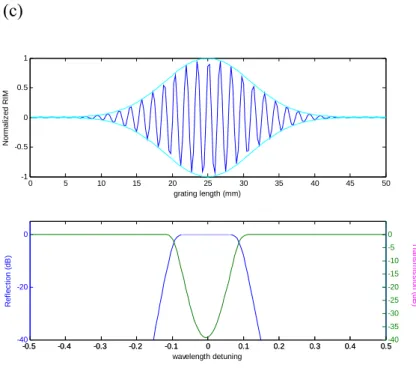
To keep average refractive index the same throughout the length of the grating, pure-apodization method is used. The aim of the method is to maintain the dose of the UV radiation the same throughout the fiber length but the fringe pattern is gradually altering. Conventional method to achieve pure-apodization relies on double UV exposure. The first exposure is to imprint the interference pattern onto the fiber core, followed by second scan to keep the total doze along the entire grating length unchanged [2.20]. The polarization control method was then proposed to inscribe the fiber with complex apodization profiles. In our group, the previous technology of producing apodized fiber grating was accordingly modified and well-developed [2.21-2.22]. Using the shaping function to apodizse the refractive index modulation of the grating and keeping the average refractive index the same along the grating length, the reflection spectrum of the FBGs is perfectly band-rejection and zero side-lobes outside. Figure 2.2(a) shows the diagram of the experimental setup. By rotating the half wave plate, the relative polarization of arms A and B changes, forming the interference pattern of maximum visibility at parallel polarizations and the interference pattern of minimum visibility at orthogonal polarizations. The average refractive index change is constant along the fiber axis due to the overlapped and equal-spaced UV shots that forms constant average UV intensity written onto the fiber, as shown in Fig. 2.2(b).
17
2.3 References
[2.1] T. Erdogan, “Fiber grating spectra,” J. Lightwave Technol. 15, 1277–1288 (1997).
[2.2] Kogelnik H. and Shank C. W., “Coupled wave theory of distributed feedback lasers,” J. Appl. Phys. 43, 2327-2335 (1972).
[2.3] Yamada M. and Sakuda. K., “Optical waveguide filters: Synthesis,” J. Opt. Soc. Am. 65, 804-809 (1975).
[2.4] Mizrahi V. and Sipe J. E., “Optical properties of photosensitive fiber phase gratings,” J Lightwave Technol. 11, 1513-1517 (1993).
[2.5] Meltz G., Morey W. W., and Glenn W. H., , “Formation of Bragg gratings in optical fibers by transverse holographic method,” Opt. Lett. 14, 823-825 (1989).
[2.6] Raman Kashyap, “Fiber Bragg Gratings,” Academic Press.
[2.7] Kenneth O. Hill, and Gerald meltz, “Fiber Bragg Grating Technology Fundementals and Overview,” J. Lightwave Technol. 15, 1263–1276 (1997). [2.8] T. E. Tasi, G. M. Williams, and E. J. Friebele, “Index structure of fiber Bragg
gratings in Ge–SiO2 fibers,” Opt. Lett. 22, 224–226 (1997).
[2.9] Honso H., Abe Y. Kinser D. L., Weeks R. A., Muta K., and Kawazoe H., “Nature and origin of the 5 eV band in SiO2:GeO2 glasses,” Phys. Rev. B 46, 445-451 (1995).
[2.10] Douay M., Xie W. X., Taunay T., Bernage P., Niay P., Cordier P., Poumellec B., Dong L., Bayon J. F., Poignant H., and Delevaque E., “Densification involved in the UV based photosensitivity of silica glasses and optical fibers,” J. Lightwave Technol. 15, 1329–1342 (1997).
18
refractive-index modulation in Bragg gratings written in Ge-doped dilica fibers,” Opt. Lett. 25, 872–874 (2000).
[2.12] P. J. Lemaire, R. M. Atkins, V. Mizrahi, and W. A. Reed, “High pressure H2 loading as a technique for achieving ultrahigh UV photosensitivity and thermal sensitivity in GeO2 doped optical fibers,” Electron. Lett. 29, 1191–1193 (1993).
[2.13] Atkin R. M., Lemaire P.J., Erdogan T., and Mizrahi V., “Mechanism of enhanced UV photosensitivity via hydrogen loading in germanosilicate glasses,” Electron. Lett. 29, 1234–1235 (1993).
[2.14] K. O. Hill, B. Malo, F. Bilodeau, D. C. Johnson, and J. Albert, “Bragg gratings fabricated in monomode photosensitive optical fiber by UV exposure through a phase mask,” Appl. Phys. Lett. 62, 1035–1037 (1993).
[2.15] K. Nakagawa, Y. Takemura, R. Kunimoto, Y. Mizutani, S. Kimura, Y. Fukuyama, Y. Suzaki, and S. Ejima, “Fabrication of Fiber Gratings with different Bragg wavelengths using a single phase mask,” Jpn. J. Appl. Phys. 41, L599-L601 (2002).
[2.16] J. Albert, K. O. Hill, D. C. Johnson, F. Bilodeau, and M. J. Rooks, “Moire phase masks for automatic pure apodisation of fibre Bragg gratings,” Electron. Lett. 32, 2260–2261 (1996).
[2.17] T. Komukai, K. Tamura, and M. Nakazawa, “An efficient 0.04-nm apodized fiber Bragg grating and its application to narrow-band special filtering,” IEEE Photon. Technol. Lett. 9, 934-936 (1997).
[2.18] Cole M. J., Loh W. H., Laming R. I., Zervas M. N., and Barcelos S., “Moving fiber/phase mask-scanning beam technology for enhanced flexibility in producing fiber gratings with a uniform phase mask,” Electron. Lett. 31, 92–94
19
(1995).
[2.19] Y. Liu, J. J. Pan, C. Gu, and F. Z. L. Dong, “Novel fiber Bragg grating fabrication method with high-precision phase control,” Opt. Eng. 43, 1916-1922 (2004).
[2.20] A Yang and Y. Lai, “Apodised fiber Bragg gratings fabricated with uniform phase mask using low cost apparatus,” Electron. Lett., 36, 655–657 (2000). [2.21] Kai-Ping Chuang and Yinchieh Lai, and Lih-Gen Sheu, “Pure Apodized
Phase-Shifted Fiber Bragg Gratings Fabricated by a Two-Beam Interferometer With Polarization Control,” IEEE Photon. Technol. Lett. 16, 834-836 (2004). [2.22] Kai-Ping Chuang and Yinchieh Lai, and Lih-Gen Sheu, “Complex fiber grating
structures fabricated by sequential writing with polarization control,” Opt. Lett.
20 (a) 0 5 10 15 20 25 30 35 40 45 50 0 0.2 0.4 0.6 0.8 1 grating length (mm) No rm a liz e d R IM -0.5 -0.4 -0.3 -0.2 -0.1 0 0.1 0.2 0.3 0.4 0.5 -40 -20 0 wavelength detuning (nm) R e fl e c ti o n ( d B) -0.5 -0.4 -0.3 -0.2 -0.1 0 0.1 0.2 0.3 0.4 0.5-150 -100 -50 0 Tr n s m is s io n ( d B ) (b) 0 5 10 15 20 25 30 35 40 45 50 0 0.2 0.4 0.6 0.8 1 grating length (mm) Norm a liz e d RI M -0.5 -0.4 -0.3 -0.2 -0.1 0 0.1 0.2 0.3 0.4 0.5 -40 -20 0 wavelength detuning (nm) R e fl e c ti o n ( d B ) -0.5 -0.4 -0.3 -0.2 -0.1 0 0.1 0.2 0.3 0.4 0.5-40 -35 -30 -25 -20 -15 -10 -5 0 T ra n sm is si o n ( d B )
21 (c) 0 5 10 15 20 25 30 35 40 45 50 -1 -0.5 0 0.5 1 grating length (mm) No rm a liz ed RI M -0.5 -0.4 -0.3 -0.2 -0.1 0 0.1 0.2 0.3 0.4 0.5 -40 -20 0 wavelength detuning R e fl e c ti o n ( d B) -0.5 -0.4 -0.3 -0.2 -0.1 0 0.1 0.2 0.3 0.4 0.5-40 -35 -30 -25 -20 -15 -10 -5 0 T ra n sm issi o n ( d B )
Fig 2.1 (a) Uniform grating index profile and spectrum. RIM: refractive index modulation. (b) Apodized grating index profile and spectrum. (c) Pure apodized grating index profile and spectrum.
22 (a) 244nm UV beam BS M HWP M A: p-pol B: p-pol A: p-pol B: s-pol A B (b)
Fig 2.2 (a) Pure apodization setup. M: Mirror, HWP: half wave plate, BS: beam splitter, A: arm A, B: arm B. (b) Sequential writing with constant average refractive index along the entire grating length.
23
Chapter 3
Fiber Bragg Grating Fabrication by
Interferometric Side-Diffraction Position
Monitoring Scheme
3.1 Narrow Band FBGs
Advanced fiber Bragg gratings (FBGs) with complex grating structures of arbitrary phase shifts and refractive index profiles have been continuously attractive for many optical communication applications, including narrow-band FBG OADMs, dispersion compensators, sensors, phase-shifted DFB fiber lasers and pulse repetition-rate multiplication [3.1-3.5]. Several procedures that can realize long and complex FBG structures have recently been developed, such as the moving-fiber-scanning-beam technique [3.6] and the sequential writing techniques [3.7]. In these methods, a conventional laser interferometer is typically utilized to monitor the fiber/UV-beam position during the writing process. However, accumulative position reading errors due to interferometer drift and inaccurate grating period estimation have caused significant difficulties on the fabrication of long-length fiber Bragg gratings.
To overcome some of these difficulties, we utilize the side-diffraction interference method [3.8] for real-time monitoring the fiber position accurately during the sequential writing process [3.9-3.11]. The side-diffraction interference technique was originally developed for measuring the variation of the grating period and the refractive-index modulation profile of the exposed FBGs [3.8]. In the literature it has
24
also been suggested that the method can be used as a position control scheme [3.12]. However, we believe our work is the first experimental report on actually using the method for real-time position monitoring during the FBG fabrication process. By directly measuring the grating phase, we can connect adjacent grating sections with accurate phase alignment.
3.2 Interferometric Side Diffraction Method
The purpose of developing interferometric side-diffraction technique was to measure the refractive-index modulation profiles of FBG devices [3.8-3.12]. In the literature, the interferometric side-diffraction technique was first proposed by Fonjallaz et. al. Then Fouad El-Diasty et. al. modified the experimental setup to preciously obtain index modulation and periodicity of FBGs.
There are numerous methods for measuring the fiber grating structure, such as optical low-coherence reflectometry, heat scanning method, side Rayleigh scattering profiling, and optical low-coherence reflectometry with scanning local heating, side-diffraction, and side-diffraction with local heating [3.13-3.18]. They are either limited in strong grating measurements or limited in short grating length. The interferometric side-diffraction method is the most precise measurement method regardless of the fiber grating length and index modulation. The advantage of the setup is due to the use of the visibility of the two beam interference pattern, so that the weaker grating can be measured by tuning the intensity ratio of the two interfered beams, and by use of the translation stage to scan entire fiber grating length. Thus, a weak index modulation profile can be determined regardless of the weak intensity of diffraction beam. According to the equation derived by Fouad El-Diasty et. al., the index modulation of the local grating section is proportional to the first order Bragg
25
diffraction intensity.
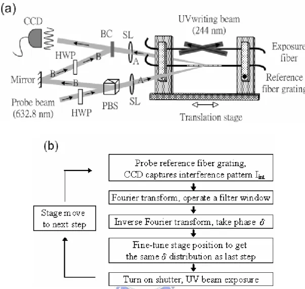
We have built an interferometric side-diffraction setup and the interference pattern is captured by a CCD camera which is automatically controlled by a computer to do the whole data processing. In our side-diffraction setup, the fiber is clamped on the translation stage with the position monitoring resolution of sub-μm by an Agilent 5519A He-Ne laser interferometer, as shown in Fig. 3.1. A 35-mW high power He-Ne laser beam of 3-mm-diameter is divided into two beams: one is the probe beam and the other is the reference beam. The probe beam is focused onto the fiber grating under test with a spherical lens of 20-cm focal length. The first-order Bragg diffraction of the probe beam is generated under the phase-matching Bragg condition. This diffracted probe beam and the reference beam are combined at the beam combiner to form an interference pattern. A 440×480 monochrome CCD camera with a pixel width of 7.15-μm is utilized to record the interference pattern produced by the two beams. The CCD is proven to have linear response to He-Ne laser power and its S/N ratio is 50 dB. The refractive index profile is obtained by analyzing the visibility of the interference pattern with Fourier transform along the whole grating. With the use of the polarization beam splitter, the power ratio of the two beams can be controlled by adjusting the angles of the waveplates to get good visibility contrast even in the weak grating case. According to Ref. [3.8], the refractive index variation is directly proportional to the amplitude of the first order diffraction beam. In our setup, the interference pattern is taken Fourier transform to get the amplitude of the beating frequency between the reference beam and the diffractive beam. Let the intensity of reference beam be Ir, and the intensity of first order diffraction beam be Id, the interference pattern distribution along x axis is I(x), and the refraction index change is Δn, then
( ) r d 2 ( r d) cos(2 )
26
and Δ =n c Id , (3.2)
where f is the spatial frequency of the interference pattern, and c is constant. In our experimental setup, the minimum detectable refractive index variation of the grating is around 5×10⁻⁶, depending on the probe laser power and the optimized intensity ratio of the divided two laser beams.
3.3 Fiber Bragg Grating Fabrication by
Interferometric Side-Diffraction Position Monitoring
In this section, two real-time side-diffraction position monitoring schemes for fabricating long fiber Bragg gratings are investigated. In the first scheme, the side diffraction position monitoring method that probes the just-exposed grating section has been developed to fabricate single-period fiber Bragg gratings. Because the grating phase of the just-exposed grating section is still affected by the later exposures due to the strongly overlap exposure scheme we use, and because it is difficult to form a clear interference pattern for the side-diffraction measurement when the refractive index modulation is lower than 3.0 × 10⁻⁵, this simple method is only suitable for fabricating single-period fiber FBGs with reasonable strength index modulation. The second scheme employs a reference fiber Bragg grating with a uniform strong refractive index profile fabricated by using the first scheme. The reference grating is placed in parallel to the exposure fiber on the moving stage. Prior to the UV exposure of every FBG section, the reference fiber grating is probed with the side-diffraction method to determine the grating phase as the reference. The measured value can then provide an accurate fiber position reference during the fabrication process. The second scheme shares the same advantage with the first scheme that the accumulative position27
measurement errors during the long fiber scan can be avoided. Moreover, it also has the following additional advantages. First of all, long FBGs with weak index modulation can be fabricated. The first scheme fails to do this because the resolution of our side-diffraction monitoring scheme is limited to 3.0 × 10⁻⁵ refractive index modulation. Secondly, phase shifts along the fiber grating can be easily inserted. The first scheme fails to do this because with the insertion of phase shifts, the grating phase of the just-exposed section will still not reach the final value due to the strongly-overlapped exposure method we use [3.9-3.11]. Thirdly, the required reference FBG can be fabricated by a similar setup (the first scheme) or by different methods (i.e., the phase mask method). In principle, the second scheme will be capable of fabricating arbitrary FBG refractive index modulation profiles with arbitrary grating phase shifts. Details of the experimental setups and the achieved results for the proposed schemes will be presented during the following sections.
3.3.1 Fiber Bragg Grating Fabrication by Interferometric
Side-Diffraction Position Monitoring with Exposed Fiber Section
Our first real-time side-diffraction position monitoring method is by probing the just-exposed fiber grating section. Figure 3.2(a) shows the schematic diagram. A 35-mW single-polarization He-Ne laser beam is expanded with two spherical lenses to achieve a final beam diameter of roughly 3 mm. It is then divided into two probe beams A and B with a polarization beam splitter. The function of the first half-wave plate is to control the intensity ratio of these two divided beams. The second half-wave plate rotates the polarization of the probe beam B relative to the probe beam A. Probe beam A is then focused onto the exposed fiber with a spherical lens of 20-cm focal length. The first-order Bragg diffraction of probe beam A is generated under the
28
phase-matching Bragg condition sinθ1=nB ⋅λ / λB, where θ1 is the input angle of the probe beam in air, nB is the effective index of the exposed fiber at the Bragg wavelength λB, and λ is the wavelength of the probe beam. Probe beam B and diffracted probe beam A are combined at the beam combiner with an interference angle of θ2. A 440×480 monochrome CCD camera with a pixel width of 7.15-μm is utilized to record the interference pattern produced by probe beams A and B. The visibility of the interference pattern can be optimized by adjusting the two half-wave plates. A frequency-doubled argon-ion laser launches a CW 244-nm single-polarization ultra-violet (UV) beam into a two-beam interferometer. Exposure of the Gaussian-shaped UV fringe with its 1/e2 width about 6.5 mm forms a periodic UV intensity pattern onto the exposed fiber to induce a single FBG section. The long fiber Bragg grating is achieved by connecting many strongly-overlapped, equally-spaced, Gaussian-shaped FBG sections with accurate grating phase alignment. A half-wave plate is placed in one path of the two interfering beams to obtain pure apodization (flat DC-index modulation) for the final FBG [3.19]. The translation stage comprises of a linear motor stage and a piezoelectric translator (PZT) stage with sub-nm position resolution. The accurate alignment of the fiber position is achieved by shifting the translation stage by a given distance and then iteratively fine-tuning the PZT stage according to the grating phase measurement of the just-exposed grating section. In our preliminary experimental setup, the position monitoring accuracy of the whole system is better than 4 nm, but the accuracy of the position-seeking feedback control loop is only set to be around 5 nm (1% of the grating period) in order to reduce the required position-seeking time. The measurement accuracy we have readily achieved is two-fold better than the estimated accuracy in Ref.[3.8]. The intensity of the first-order diffracted probe beam A is denoted as IA, and the intensity of the probe beam B is
29
assumed to be IB. The intensity distribution of the interference fringe on the CCD along the x-axis, which is perpendicular to the bisector of the two interfering beams, is given by ] ) 2 sin( 2 cos[ 2 2 int δ θ + ⋅ ⋅ + + =I I I I kx I A B A B , (3.3) where k=2π/λ is the wave vector, θ2 is the interfering angle and δ is the phase difference between the two interfering beams. The phase difference δ contains two contributions,
grating path difference
δ δ
=
+
δ
, (3.4) where δgrating is the phase change of the diffracted probe beam A caused by the fiber grating, and δpath difference is the phase change caused by the optical path difference between two probe beams. Since δpath difference is constant during the scan, the grating phase change can be inferred from monitoring the phase difference δ. The interference pattern Iint is processed by the Fourier transform to obtain the corresponding spatial frequency spectrum. The spectrum is then filtered to keep only the positive frequency part and is inverse-Fourier-transformed back to the original domain. The phase δ can then be identified by taking the arg of the processed data. Figure 3.2(b), Fig. 3.3(a) and Fig. 3.3(b) show the typically resulted periodic pattern captured by the CCD camera (grey solid line), the pattern after the filtering + taking-real-part procedure (grey dotted line) and the obtained phase distribution by taking the arg of the filtered data (bold solid line). For producing single period FBGs, the PZT stage is fine tuned until the just-exposed fiber grating phase distribution obtained in this step is the same as that of last step. The UV-beam shutter is then turned on for writing the present FBG section with a given time duration. In practice, the whole algorithm is implemented with the LabVIEW software for automatically controlling the whole exposure process.
30
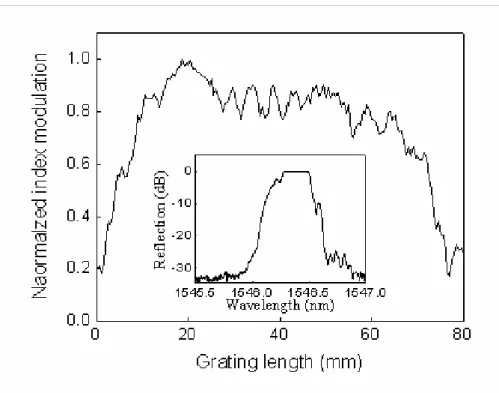
just-exposed section has been employed for preparing a single-period fiber grating with strong index-modulation. The fiber used is the photosensitive fiber (Fibercore PS1500) after 1,900-psi hydrogen loading at room temperature for several days. The Gaussian-shaped UV fringe has its 1/e2 width about 6.5 mm and the fiber scan step is about 1mm. The final FBG is produced after a 80-section sequential writing to reach a total grating length about 80 mm. The same side-diffraction method [3.8] is applied to measure the whole refractive index modulation profile of the fabricated fiber grating. Figure 3.4 shows the measured result. One can see that the fabricated fiber grating profile is substantially uniform. The optical reflection spectrum in the inset of Fig. 3.4 shows that the Bragg wavelength is 1.546 μm and there should be no obvious phase errors. Such a FBG will be used as the reference grating for the scheme in next section.
3.3.2 Fiber Bragg Grating Fabrication by Interferometric
Side-Diffraction Position Monitoring with Reference Fiber
Grating
In the second scheme, the experimental setup includes a reference fiber grating and an exposure fiber which are clamped in parallel on the same moving stage. Figure 3.5(a) depicts the schematic diagram of the system. The reference grating with a strong and uniform refractive index modulation is prepared in advance with the first scheme. The reference fiber grating under probe is adequately uniform and has a sinusoidal index modulation profile n(x) along its fiber axial direction as
)) ( 2 cos( ) (x n0 n x x n π +φ Λ ⋅ Δ + = , (3.5) where n0 is the average refractive index, Δn is the amplitude of refractive index modulation, Λ is the grating period, and φ(x) describes spatial grating phase. The
31
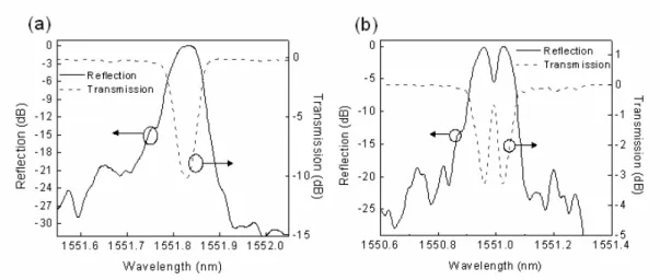
UV-generated interference period is fine tuned to match the reference fiber grating period, even though this restriction can be relaxed since it will only cause a center-wavelength shift. The accurate alignment of the fiber position is achieved by shifting the translation stage by a given distance and then iteratively fine-tuning the PZT stage according to the reference grating phase measurement. The UV-beam shutter is then turned on for writing the present FBG section with a given time duration. Figure 3.5(b) reveals the flow chart of the whole operation algorithm. In principle, this method should be able to fabricate long fiber Bragg gratings even when the index-modulation is small and with the option for easy insertion of arbitrary phase shifts. We have verified the feasibility of the proposed method by two examples. The first example is to fabricate a narrowband, Gaussion apodized FBG with a constant DC refractive index modulation along the whole grating, as shown in Fig. 3.6(a). The reference grating with uniform and strong refractive index modulation is probed to identify the related grating phase information. The Gaussian-shaped UV fringe has its 1/e2 width about 6.5 mm and the fiber scan step is about 1.2 mm. The final FBG is produced after a 58-section sequential writing to reach a total grating length about 70 mm. Before the UV writing process, a DC pre-UV treating process is applied to avoid the nonlinear regime when the exposure UV flux is small [3.20]. Figure 3.7(a) shows the reflection and transmission spectra of the exposed FBG. The reflection spectrum has a relatively flat top with the sidelobe level below -20 dB. The 3-dB bandwidth of the reflection spectrum is only 0.07 nm. The peak refractive index modulation is estimated to be 2.5×10⁻⁵ for this 70-mm-long Gaussian apodized FBG, determined by simulation-fitting. This example demonstrates the feasibility for fabricating long fiber Bragg gratings without noticeable phase errors, even when the written index modulation is below the threshold for reliable side-diffraction measurement.
32
The second example is to fabricate a 40-mm-long, single π-phase-shifted Gaussion apodized FBG with a constant DC refractive-index modulation, as shown in Fig. 3.6(b). The scan step during the exposure is about 0.6 mm and the final FBG is achieved by connecting 70 FBG sections. A π phase shift is inserted into the center of the exposure fiber grating during the fabrication process. Figure 3.7(b) shows the reflection and transmission spectrum of the exposure fiber. As expected, there is a narrow transmission peak within the stop-band due to the resonance caused by the π-phase-shift. This simple example demonstrates the feasibility of fabricating phase-shifted FBGs with the new scheme.
3.4 Summary
In conclusion, we have proposed and demonstrated a real-time fiber position monitoring method for sequential UV-writing processes by using the interferometric side-diffraction technique. This new method (the second scheme) is capable of fabricating long FBGs with weak index modulation and easily to insert phase shifts along the fiber grating. Furthermore, the required reference FBG can be fabricated by a similar setup (the first scheme) or by different methods (i.e., the phase mask method). Several preliminary examples have been experimentally demonstrated for proving the feasibility of the new method. Hopefully this new method is promising for increasing the accuracy and the ease of fabricating complicated long FBG devices.
33
3.5 References
[3.1] T. Komukai, K. Tamura, and M. Nakazawa, “An efficient 0.04-nm apodized fiber Bragg grating and its application to narrow-band spectral filtering,” IEEE Photon. Technol. Lett. 9, 934–936 (1997).
[3.2] J. T. Kringlebotn, J. L. Archambaut, L. Reekie, and D. N. Payne, “Er3+:Yb3+-codoped fiber distributed-feedback laser,” Opt. Lett. 19, 2101-2103 (1994).
[3.3] Junfeng Jiang, Tiegen Liu, Yimo Zhang, Lina Liu, Ying Zha, Fan Zhang, Yunxin Wang, and Pin Long, “Parallel demodulation system and signal-processing method for extrinsic Fabry–Perot interferometer and fiber Bragg grating sensors ,“Opt. Lett. 30, 604-606 (2005).
[3.4] Naum K. Berger, Boris Levit, Shimie Atkins, and Baruch Fischer, “Repetition-rate multiplication of optical pulses using uniform fiber Bragg gratings,” Opt. Commun. 221, 331-335 (2003).
[3.5] Xu Wang, Koji Matsushima, Ken-ichi Kitayama, Akihiko Nishiki, Naoya Wada and Fumito Kubota, “High-performance optical code generation and recognition by use of a 511-chip, 640-Gchip_s phase-shifted superstructured fiber Bragg grating,” Opt. Lett. 30, 355-357 (2005).
[3.6] M. J. Cole, W. H. Loh, R. I. Laming, M. N. Zervas and S. Barcelos, “Moving fiber/phase mask-scanning beam technique for enhanced flexibility in producing fibre gratings with uniform phase mask,” Elect. Lett. 31, 1488-1490 (1995).
[3.7] Petermann, B. Sahlgren, S. Helmfrid, A. T. Friberg, and P.-Y. Fonjallaz, “Fabrication of advanced fiber Bragg gratings by use of sequential writing with a continuous-wave ultraviolet laser source,” Appl. Opt. 41, 1051-1056 (2002).
34
[3.8] F. El-Diasty, A. Heaney, and T. Erdogan, “Analysis of fiber Bragg gratings by a side-diffraction interference technique,” Appl. Opt. 40, 890-896 (2001).
[3.9] K.-P. Chuang, I.–L. Wu and Yinchieh Lai, “Interferometric side-diffraction position monitoring technique for writing long fiber Bragg gratings,” CLEO/IQEC, CThM6 (2004).
[3.10] Kuei-Chu Hsu, Lih-Gen Sheu, Kai-Ping Chuang, Shu-Hui Chang and Yinchieh Lai, “Fiber Bragg grating sequential UV-writing method with real-time interferometric side-diffraction position monitoring,” Opt. Express 13, 3795-3801 (2005).
[3.11] Kuei-Chu Hsu, Lih-Gen Sheu, and Yinchieh Lai, “Fabrication of Fiber Bragg Gratings by Sequential UV-Writing with Real-Time Interferometric Side-Diffraction Position Monitoring”, ECOC2005, We4.P.132.
[3.12] Mattias Åslund, John Canning, Leon Poladian, and C. Martijn de Sterke, “Novel characterization technique with 0.5 ppm spatial accuracy of fringe period in Bragg gratings,” Opt. Express 11, 838-842 (2003).
[3.13] N. Roussel, S. Magne, C. Martinez, and P. Ferdinand, “Measurement of index modulation along fiber Bragg gratings by side scattering and local heating techniques,” Opt. Fiber Technol. 5, 119–132 (1999).
[3.14] P. A. Krug, R. Stolte, and R. Ulrich, “Measurement of index modulation along an optical fiber Bragg grating,” Opt. Lett. 20, 1767–1769 (1995).
[3.15] W. Margulis, I. G. Carvalho, and P. M. Gouvea, “Heat scan: a simple technique to study gratings in fiber,” Opt. Lett. 18, 1016–1018 (1993).
[3.16] P. Lambelet, P. Y. Fonjallaz, H. G. Limberger, R. P. Salathe, Ch. Zimmer, and H. H. Gilgen, “Bragg grating characterization by optical low-coherence reflectometry,” IEEE Photon. Technol. Lett. 5, 565–567 (1993).
35
[3.17] B. L. Danielson and C. D. Whittenberg, “Guided-wave reflectometry with micrometer resolution,” Appl. Opt. 26, 2836– 2842 (1987).
[3.18] K. Takada, I. Yokohama, K. Chida, and J. Noda, “New measurement system for fault location in optical waveguide devices based on an interferometric technique,” Appl. Opt. 26, 1603–1606 (1987).
[3.19] K.-P. Chuang, Y. Lai, and L.-G. Sheu, “Pure apodized phase-shifted fiber Bragg gratings fabricated by a two-beam interferometer with polarization control,” IEEE Photon. Technol. Lett. 16, 834-836 (2004).
[3.20] B.-O. Guan, H.-Y. Tam, X.-M. Tao, and X.-Y. Dong, “Highly stable fiber Bragg gratings written in hydrogen-loaded fiber,” IEEE Photon. Technol. Lett. 12, 1349-1351 (2000).
36
Figure 3.1. Experimental setup of side-diffraction method. HWP: half wave plate, PBS: polarization beam splitter.
37
Fig. 3.2. (a) Real-time side-diffraction position monitoring setup by probing the just-exposed section. SL: spherical lens; BC: beam combiner; PBS: polarization beam splitter; HWP: half wave plate. (b) Typical interference pattern captured by CCD, the pattern after procedure (filtering+taking-real-part) and the calculated phase distribution.
38
(a)
(b)
Fig. 3.3. (a) Interference pattern captured by CCD. (b) White line: Original pattern, Red line: Pattern after , procedure, Green line: Periodic phase.
39
40
Fig. 3.5. (a) Real-time side-diffraction position monitoring setup by probing the reference grating. (b) Flow chart of the algorithm.
41
(a)
(b)
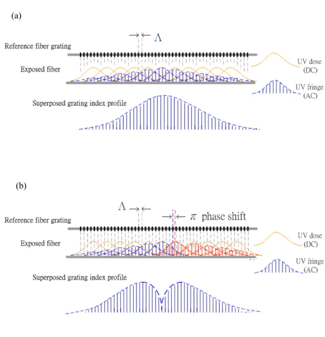
Fig. 3.6. (a) Illustration of side-diffraction interferometric position monitoring method to fabricate Gaussian apodized FBG. (b) Illustration of side-diffraction interferometric position monitoring method to fabricate phase-shifted Gaussian apodized FBG.
42
Fig. 3.7. (a) Reflection and transmission spectra of a 0.07-nm Gaussian apodized 70-mm long FBG. (b) Reflection and transmission spectra of a 40-mm long, π-phase-shift Gaussian apodized FBG.
43
Chapter 4
Methods of Achieving Linear Index-Change
Response for Narrow-Band Fiber Bragg Grating
Sequential Writing
4.1 Introduction
Fiber Bragg grating (FBG) devices as narrowband filters and dispersion
compensators have numerous applications in Dense-Wavelength-Division-Multiplexing (DWDM) systems and fiber lasers [4.1,4.2].
FBGs with complex grating index profiles and multiple phase shifts can also be inversely designed to perform advanced filtering functions [4.3-4.5].The relationship between the UV flux to which the device is exposed and the induced refractive index change must be calibrated carefully in fabricating precisely these complex grating profiles and phase-shifts. The induced index change in the fiber core is not a linear function of the exposed UV flux but a complicated curve [4.6]. The curve is nonlinear at low UV flux and linear elsewhere before saturation. For narrow-band FBG devices with long grating length and small index changes, the nonlinear photosensitivity makes difficult the realization of a perfect grating profile, influencing the reflection spectrum of the grating and degrading its performance. Accordingly, the UV writing must be conducted in the linear regime, so that an FBG with an arbitrary index modulation profile can be easily realized.
Pre UV treatment is initially proposed to enhance the photosensitivity of optical fibers and increase the stability of the FBG devices [4.7], yet the advantage of the