國
立
交
通
大
學
網路工程研究所
碩
士
論
文
點對點即時路況導航系統
P2P Real-Time Road Traffic Navigation System
研 究 生:楊雅筑
指導教授:曹孝櫟 教授
點對點即時路況導航系統
P2P Real-Time Road Traffic Navigation System
研 究 生:楊雅筑 Student:Ya-Chu Yang
指導教授:曹孝櫟 Advisor:Shiao-Li Tsao
國 立 交 通 大 學
網 路 工 程 研 究 所
碩 士 論 文
A ThesisSubmitted to Institute of Network Engineering College of Computer Science
National Chiao Tung University in partial Fulfillment of the Requirements
for the Degree of Master
in
Computer Science
September 2007
Hsinchu, Taiwan, Republic of China
點對點即時路況導航系統
學生: 楊雅筑
指導教授: 曹孝櫟 博士
國立交通大學網路工程研究所碩士班
摘要
隨著道路狀況日益複雜以及車輛日漸普及,為了增加駕駛人行車的便利性,於是就出現 了集中式的路況導航系統。此系統雖然能提供即時路況資訊,幫助駕駛人做最佳路徑的 選擇,然而卻需要相當昂貴的建置及維護費用。於是有文獻提出了非集中式的路況導航 系統,在此系統中,車輛直接透過車間通訊互相交換彼此觀察到的路況,省卻了路況中 心的建置費用。然而此系統在交通密度低的情況下路況交換較為困難,車輛要獲得遠距 離道路資訊會受到較長時間的延遲。因此我們提出了結合車間通訊及無線網路(WiFi, WiMAX, or 3G)的非集中式點對點路況導航系統。本系統採取了階層式的架構,我們利 用點對點網路將車間通訊網路可能離散的部份接起來,讓路況資訊的交換不再受到車間 通訊傳輸半徑及車流密度的限制。本系統的目標在於讓駕駛人能夠迅速的獲得正確且即時的道路資訊。在本篇論文的最後,我們會透過實驗數據說明本系統的確能幫助駕駛人 作有效率的路況查詢。
P2P Real-Time Road Traffic Navigation System
Student: Ya-Chu Yang
Advisors: Dr. Shiao-Li Tsao
Institute of Network Engineering
National Chiao Tung University
Abstract
Existing centralized real-time traffic information systems provide excellent road guidance. However, the cost for constructing and maintaining the traffic center is expensive. Recently, several decentralized ad-hoc based traffic information systems are proposed. Vehicles in this kind of system detect traffic conditions with GPS devices and exchange observed traffic conditions with each other through inter-vehicle communication. However, ad-hoc based traffic information system has problem to efficiently disseminated traffic condition in large scale places when the penetration rate is low. For this reason, we propose a combined IVC and infrastructure-based decentralized P2P real-time road traffic information system. The system aims at providing accurate traffic reports and supporting efficient traffic report lookup. The system is organized as a two-layer hierarchical architecture. All vehicles participate in the
ad-hoc network and broadcast observed traffic condition through IVC. Parts of vehicles are elected as super nodes and they form a P2P overlay atop ad-hoc network to support traffic report lookup through infrastructure-based wireless network interfaces. Simulation results demonstrate that the proposed system dose provide efficient traffic report lookup.
誌謝
本論文得以順利完成,首先要感謝指導教授 曹孝櫟 博士的教誨,老師在專業能力 上面給予了我們紮實的訓練,從如何發現問題,如何針對問題找出解決方法,到如何邏 輯性的闡述我們的想法,以及最後將我們的想法轉化成流暢的文章,都是老師所重視 的,進入實驗室的這兩年著實獲益良多。同時也要感謝口試委員 鄭瑞光 教授,彭文志 教授和 曾建超 教授,給予了許多寶貴的意見,使本論文更趨完整。 接下來要特別感謝 P2P Group 的成員們,建明學長帶領著我們共同討論,在論文寫 作的期間常常給予我許多建議,也時常分享他的經驗豐富我們的生活;名杰是一個值得 信賴的好伙伴,幾次共同參加比賽合作起來總是很愉快。另外也要感謝實驗室其他學 長、同學和學弟們,在研究過程中給予我的鼓勵與幫助。一正學長跟宥霖學長具備了很 深厚的專業知識,遇到問題去請教他們時總是能得到熱情的回應;同屆的中暉,誌謙, 彥筑和政龍總是與我並肩作戰互相打氣,有了他們讓我在碰到困難時還是能夠堅定的面 對問題。認真的學弟們建臻、家祥和世永給予了我許多精神上的支持與幫助。實驗室的 氣氛總是很融洽,不管是誰都是我學習的目標,能夠在這個實驗室跟大家相遇,真是太 幸運了。 最後,要感謝父母親以及許多親朋好友給予我無上限的支持,讓我能夠沒有後顧之 憂的順利完成學業。謝謝浩天三年多來的陪伴。謝謝交大,帶給了我許多美好的回憶。Table of Contents
摘要...i Abstract...iii 誌謝...v Table of Contents...vi List of Figures...viiList of Tables ...viii
Chapter 1. Introduction ...1
Chapter 2. Related Work ...6
Chapter 3. Background...8
Chapter 4. System Design ...12
4.1. Assumption...13
4.2. Super node selection...14
4.3. P2P overlay construction ...16
4.4. Traffic report generation...18
4.5. Traffic report lookup...19
Chapter 5. Simulation...23
5.1. Simulation setting...23
5.2. Simulation result...25
Chapter 6. Conclusion...28
List of Figures
Figure 1. Centralized traffic information system: (a) sensor based (b) FCD based ...1
Figure 2. Decentralized ad-hoc based traffic information systems ...2
Figure 3. Hybrid decentralized road traffic information system architecture ...4
Figure 4. Chord: (a) peer identifier and key management (b) finger table of peer 8 ...9
Figure 5. Gnutella: peer K initiate a resource lookup...10
Figure 6. Road segment and Segment ID...13
Figure 7. UDG of a network of 18 nodes ...14
Figure 8. Maxmin d-hop clustering ...15
Figure 9. A small world graph ...17
Figure 10. Traffic report lookup ...21
Figure 11. Lookup latency in Small World overlay and Gnutella overlay ...25
Figure 13. Lookup latency in Small World overlay and Gnutella overlay...26
Figure 12. Lookup message overhead in Small World overlay and Gnutella overlay ...27
List of Tables
Table 1. WINNER log of 3-hop cluster formation in a network of 18 nodes...15
Table 2. Level of Service table ...19
Table 3. SUMO traffic simulator parameter setting ...23
Chapter 1. Introduction
With the development of road network and the increase of vehicles, traffic situation becomes more and more complex. In recent years, people pay a lot of attentions on ways to increase their driving convenience. Today, it is fairly common that people equip their vehicles with Global Positioning System (GPS) devices for driving path guidance. Unfortunately, GPS navigation system provides only one-way location information. Real-time road traffic information is not available for drivers to make optimized route path selection.
(a) (b) Figure 1. Centralized traffic information system: (a) sensor based (b) FCD based
One possible solution is to construct a centralized real-time traffic information center such as Intrix[3], EFCD[4], TaxiFCD [5] TrafficMaster [6]. The center is responsible for collecting traffic conditions from different kinds of sources such as roadside sensors, or floating cars. In the sensor-based method, as illustrated in Figure 1 (a), a large number of sensors have to be
deployed along the roadway to monitor traffic conditions. As to the floating car data (FCD) method, as showed in Figure 1 (b), vehicles in this system are equipped with GPS receivers and act as mobile sensors to detect traffic condition of the road they currently traverse on. Traffic conditions measured from sensors or floating cars are periodically transmitted back to the center. Traffic center performs traffic condition filtering and aggregation to generate traffic report of each road. Drivers can retrieve traffic reports that they are interested in directly from traffic center through webpage interface or short message service (SMS). With real-time traffic reposts, drivers can easily make good route selections. However, construction and maintenance costs of the traffic information center are fairly expensive.
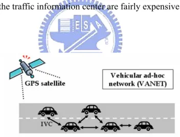
Figure 2. Decentralized ad-hoc based traffic information systems
For this reason, decentralized ad-hoc based traffic information systems, as illustrated in Figure 2, are proposed. Vehicles in this system are equipped with GPS devices and digital radios. The way how traffic conditions are detected are exactly the same as the FCD-based method in the centralized traffic information system. However, the way drivers retrieve traffic
reports is totally different because of the absence of centralized traffic center. With aid of digital radios, vehicles can communicate with each other through inter-vehicle communication (IVC) [2]. Vehicles periodically broadcast observed traffic conditions to other vehicles within their one-hop transmission range. Once receiving broadcast packets from others, vehicles update their traffic condition database and include newly observed information in next broadcast packets. In this way, traffic report can be gradually disseminated.
Decentralized ad-hoc based system does eliminate the construction and maintenance cost of
traffic information center. However, under the situation where traffic density or penetration1
rate is low, vehicles have problem to encounter communication buddies to exchange traffic conditions with. In this case, traffic conditions can not be efficiently disseminated to large-scale places; therefore the latency for retrieving distant traffic conditions is long.
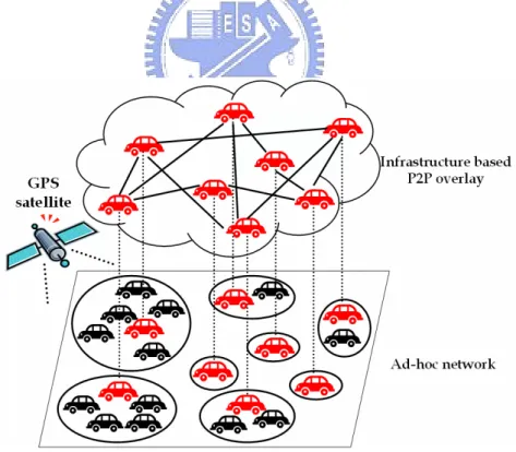
In this paper, we aim at providing solutions to construct a traffic information system which eliminate the construction and maintenance cost of traffic center and support efficient traffic reports lookup. We propose a two-layer hierarchical decentralized P2P real-time road traffic information system. The system architecture is illustrated in Figure 3. It is assumed that each vehicle has two wireless network interfaces: IVC and infrastructure-based wireless interface
(such as WiFi, WiMAX, or 3G). All vehicles participate in the ad-hoc network and broadcast observed traffic condition through IVC. Parts of vehicles are elected as super nodes and they are responsible for traffic condition collection and traffic report generation. Moreover, these super nodes turns on infrastructure-based wireless network interfaces and form a P2P overlay to support traffic report lookup. The P2P overlay is organized in an unstructured fashion, and we add the unstructured overlay with small world property by considering geographical characteristics of vehicles. The feature of the overlay is that geographically close super nodes are highly clustered, and short cuts can be found between distant super nodes. Through small world P2P overlay, vehicles can perform traffic report lookup to search traffic report.
Figure 3. Hybrid decentralized road traffic information system architecture
lookup latency, (2) lookup message overhead. Simulation results show that the two-layer hierarchical traffic information system does provide efficient traffic report lookup.
The rest of the paper is organized as follows: We discusses related works and describes the shortcomings of each design in Chapter II. In Chapter III, a brief overview of P2P overlay is introduced. Details about system design are described in Chapter IV. In Chapter V, performance our design is evaluated according to simulation results. Finally we present our conclusion and future works in Chapter V.
Chapter 2. Related Work
For these reason, Decentralized ad-hoc based traffic information systems such as [7], TrafficView[8], SOTIS[9][10], are proposed.
[7] is a traffic system which proposes zone-based organization methodologies to dynamically group vehicles together for group members to collect information that is relevant to their driving safety. Because this system focuses merely on safety information, the population of a group is limited to a small number and the geographical distribution of members is usually local. Therefore, it can hardly to be extended to provide large scale traffic information.
TrafficView[8] takes the diffusion mechanism for vehicles to gather and disseminate traffic information and road conditions in front of them. Also, data aggregation techniques are proposed to include more information in a packet while the accuracy of distant traffic information may be sacrificed.
SOTIS[9][10] presents segment-oriented data abstraction and dissemination (SODAD) for traffic information distribution. Moreover, vehicles can dynamically adapt broadcast interval through observing two kinds of events: provocation and mollification to avoid overload
conditions and to favor the propagation of significant information changes.
Generally speaking, ad-hoc based traffic information system can be rapidly constructed at low cost. However, under the situation where the penetration is low, the whole network is likely to be separated into several disjoint parts. The network disjoint phenomenon causes two serious problems. First, traffic information has problems to be disseminated to distant places. Even though it can reach distant place, traffic information is likely to be outdated. Outdated information is useless for vehicles to determine current situation. Second, active traffic information search can hardly be performed because the disjoint network may result in high search failure rate.
Chapter 3. Background
In this chapter, we first provide an overview about decentralized P2P overlay networks. Then, we introduce two categories of decentralized P2P overlay networks. In the end of this chapter, we make a conclusion on what kind of overlay is more suitable for a traffic information system.
In a decentralized P2P overlay, there is no central server to handle resource query, but rather peers cooperatively process resource query over the P2P overlay to locate resources they are interested in. To construct a P2P overlay, each peer maintains a small set of peers as its neighbors and establishes logically links with them. The neighbor relationship determines the topology of the P2P overlay. Decentralized P2P overlay network can be classified into two categories: structured and unstructured, according to how peers make neighbor selection.
In structured P2P overlay networks such as Chord[11], Pastry[12], Tapestry[13], and CAN[14], rules for neighbor selection and resource index management are fairly strict. Peers construct neighbor table based on distributed hash table (DHT). Also, peers publish indexes of resources that they own to certain peer according to DHT. To lookup a resource, peers consult their neighbor table and forward the query to the neighbor who is logically closest to the peer
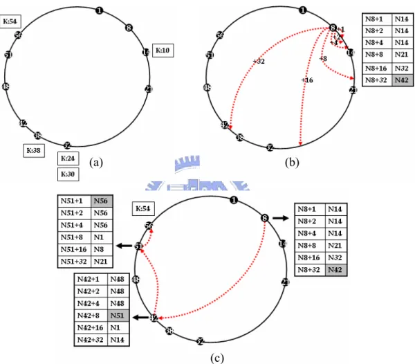
who maintains the index of the target resource. In Figure 4, we use Chord as a example to
illustrate how key management, finger table2 construction, and resource lookup are performed
in a structured P2P overlay network.
(a) (b)
(c)
Figure 4. Chord: (a) peer identifier and key management (b) finger table of peer 8 (c) peer 8 lookup resource 54
With neighbor strictly selected and index rigidly placed, structured P2P overlay networks provide efficient resource lookup. However, in the face of an environment with high churn rate, peers have to make great effort on keeping neighbor relationship and index placement
correct to guarantee successful resource lookups. Peers may be overwhelmed by handling such a large number of maintenance messages to reconstruct the overlay.
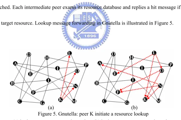
In an unstructured P2P overlay network such as Gnutella [15], neighbor links are randomly established. Peers just take care of their own resources and index of resource is not published to other peers. Peers have no knowledge about the mapping between resources and their owners; therefore they perform scoped flooding to locate resources. Each peer forwards lookup message to it neighbors and this process repeats until a predefined hop bound is reached. Each intermediate peer exams its resource database and replies a hit message if it has the target resource. Lookup message forwarding in Gnutella is illustrated in Figure 5.
Figure 5. Gnutella: peer K initiate a resource lookup
(a) (b) (a) lookup message proceeds one hop (b) lookup messages proceed two hop
Unstructured P2P overlay networks have some disadvantages. Scoped flooding may result in a large amount of lookup messages. A lookup may fail because the lookup scoped is restricted
by hop bound. However, unstructured P2P overlay is less invulnerable to churn because failed neighbor links can easily be replaced and index publishing is eliminated.
Based on above discussion and the research done by [16], we find that it is more suitable to organize peers into an unstructured P2P overlay network in an environment with high churn rate. Therefore, in our system design, the P2P overlay network atop ad-hoc network will be organized in an unstructured fashion. Details about how the overlay is constructed and how ad-hoc network and infrastructure-based overlay work together are described in next chapter.
Chapter 4. System Design
The system we proposed is a two-layer hierarchical decentralized P2P real-time road traffic information system. In the lower layer, vehicles broadcast observed traffic condition through IVC. However, under the situation where traffic density or penetration rate is low, vehicles have problem to encounter communication buddies to exchange traffic conditions with. In this case, traffic conditions can not be efficiently disseminated to large-scale places and the latency for retrieving distant traffic conditions is long. Therefore, we build a P2P overlay atop to bridge possible disjoint parts in the lower layer. Each vehicle makes super node selection to determine if it shall become a super node. Afterwards, super nodes turn on their infrastructure-based wireless network interfaces and form a P2P overlay. In the way, efficient traffic report lookup can be performed.
In this chapter, we first introduce the system assumption that we made. Then, we describe how we make super node selection. Next, we present the construction of P2P overlay network. In the next, we talk about traffic condition collection and traffic report generation. Finally, we explain how peers perform traffic report lookup.
4.1. Assumption
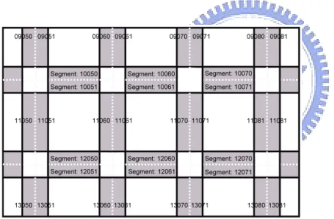
1) Vehicles should be equipped with GPS receivers and digital maps. Combined with GPS receivers and maps, vehicles are able to link their geographic coordinates to their locations on maps. Roads on the digital map are divided into segments. Each segment is assigned with a Segment ID (SID) and has a well defined start and end points pair, direction, number of lanes, and a speed limit profile. The way how segments are defined is illustrated in Figure 6 (a) (b).
Figure 6. Road segment and Segment ID
2) Vehicles must have two network interfaces. Each vehicle should be equipped with a digital radio for inter-vehicle communication and has infrastructure-based wireless network accessibility for P2P overlay network communication. Vehicles should always turn on inter-vehicle communication interface to broadcast traffic condition they observe. While they turn on the infrastructure-based network interface only when it is elected as
super node.
4.2. Super node selection
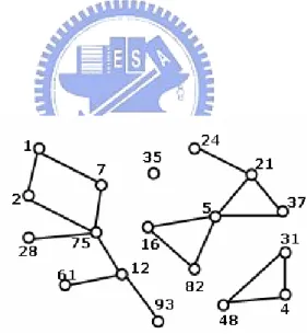
Vehicles communicate through IVC can be viewed as a mobile ad-hoc network. A wireless ad-hoc network can be modeled as a unit disk graph (UDG) G = (V, E) in which V, |V| = n, is the set of peers and there is an edge (u, v) in E, |E| = m, if and only if u and v are within each other’s one-hop transmission range. Figure 7 illustrates a mobile ad-hoc network of eighteen nodes modeled by UDG.
Figure 7. UDG of a network of 18 nodes
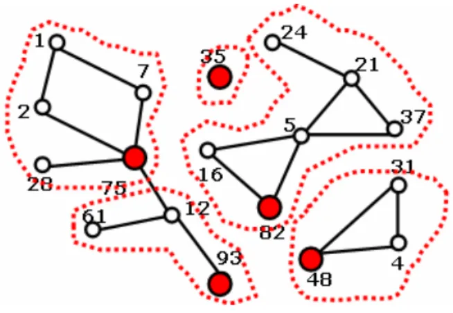
We apply max-min d-cluster formation [17] for super node3 selection. Max-min d-cluster
formation can be divided into four phases4:initial phase, floodmax phase, floodmin phase, and
3 Super nodes here are originally called as clusterhead in [17].
super node selection phase. After the first three phases, each node will get a log as illustrated in Table 1. Based on analyzing this log, each peer determines if it should become a super node. After the complete the entire max-min d-cluster formation process, each node is either a super node or at most d hops away from a super node where parameter d can be dynamically
adjusted according to traffic density. Figure 8 illustrate a mobile ad-hoc network of eighteen nodes after max-min d-cluster formation.
Table 1. WINNER log of 3-hop cluster formation in a network of 18 nodes
Due to the mobility of nodes in an ad-hoc network, nodes may move away from the super node they originally selected. Therefore, nodes must be continuously reselected in a timely fashion.
4.3. P2P overlay construction
As mentioned in Chapter 3, it is more suitable to organize super nodes in vehicular network as an unstructured P2P overlay. After considering the geographical characteristic of traffic
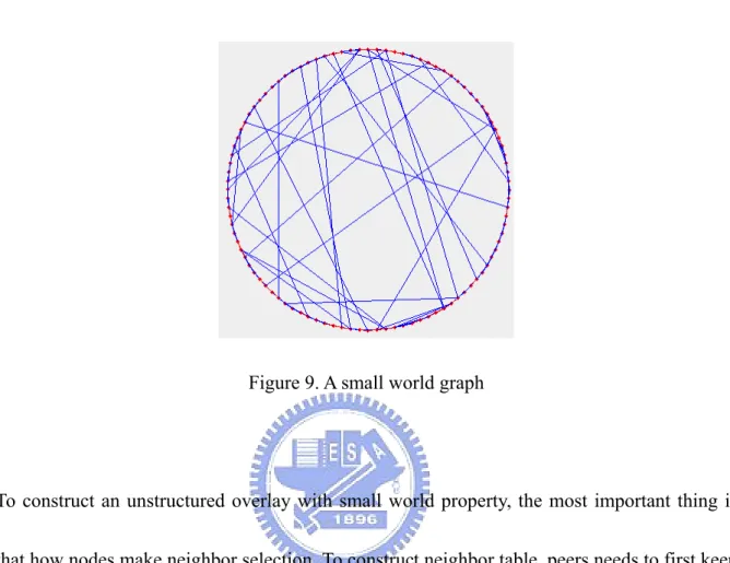
conditions and their owner5, we design the overlay as a small world network [18] [19], a
special case of random network. Each node in a small world graph keeps both regular and random links. Small-world networks have two important features: (1) shortest characteristic path length as random network and (2) high cluster coefficient as well-ordered network. Figure 9 illustrated a example of small world graph with random probability α=0.2..
In our system, we use geographical relation as the measure of link selections. We define
regular links as links between geographically nearby super peers. Random links are selected
randomly. Each node in a small world graph keeps both geographically nearby links and random links. Based on the link selection mechanism, geographically nearby super peers are highly clustered. In addition, the overlay can be guaranteed to be connected because it also
has the property of random network.
Figure 9. A small world graph
To construct an unstructured overlay with small world property, the most important thing is that how nodes make neighbor selection. To construct neighbor table, peers needs to first keep a candidate list. Nodes in candidate list are candidates for neighbor table. Candidates can be super nodes which a node previously contacts or can be obtained from traffic condition packets it receives. If candidates are all failed (become normal nodes or exit the system), this node can retrieve super node information through well-known bootstrap nodes.
After obtaining candidates, super peers can start building neighbor table. First, neighbor table size is set to k which means each peer keeps k neighbors. Then, we set random probability p which indicates the percentage of random neighbor links. Random probability p ranges from 0
to 1. Therefore, each peer keeps k(l-p) nearby links and kp random links. After finishing the neighbor table construction, peers accomplish the overlay join procedure. During the lifetime (period peers participate in the overlay) of peers, they can obtain new candidate information through the interaction between different super peers. An update period Tu is set to schedule periodically neighbor table update.
4.4. Traffic report generation
Each peer periodically broadcasts traffic condition of the road segment it currently observes its super node through IVC. We define the broadcasting period as Tb. Each super node may receive traffic condition of different segments from different vehicles. Different traffic conditions from different peer of the same segment should be aggregate into single traffic reports.
If peer Pi receive N traffic conditions C(V1, Si), C(V2, Si), …, C(VN, Si) from vehicles V1,
V2, … , VN about segment Si at time Tk. Here, we use traveling speed of a vehicle to represent
the traffic condition it observes. The average traffic condition can be computed by applying aggregation function R(Si, Tk).
N ) S C(V ) S C(V ) S C(V ) S C(V Avg T S R N k i k i N i i k i
∑
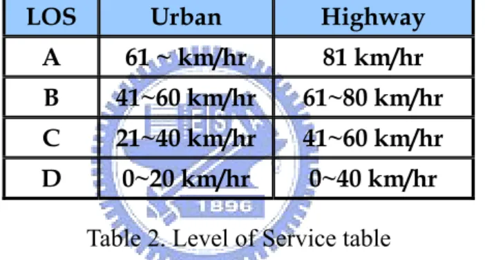
= = = 1 2 1 , ) , ,..., , , , ( ) , (The average traffic condition is then mapped to traffic level of service (LOS). A traffic report of a road segment consists of a LOS value to indicate its average traffic condition and a timestamp to record when this traffic report is generated. Table 2 lists traffic LOS range in Urban and Highway environment.
LOS Urban Highway
A 61 ~ km/hr 81 km/hr
B 41~60 km/hr 61~80 km/hr
C 21~40 km/hr 41~60 km/hr
D 0~20 km/hr 0~40 km/hr
Table 2. Level of Service table
Each peer keeps a traffic report database to maintain all traffic reports it generates or receives
from other peers. To guarantee the correctness of traffic reports, a lifetime ΔT is defined to
bound the valid period of traffic reports. Traffic reports exceeds lifetime ΔT should be
discarded because it may not be fresh enough to reflect current traffic condition.
Traffic report lookup is a procedure which peers search traffic reports that they are interested in. The lookup procedure is performed mainly through P2P overlay. A successful lookup requires the lookup message to reach one of the super nodes who manage the traffic report of target segment or any other super peers who holds a cache.
In our design, lookup messages are forwarded using location based routing [20][21] instead of scoped flooding which traditional unstructured P2P overlay network usually applies. Location based routing are routing protocols which use positional information for next hop selection to reduce lookup message overheads. Super nodes know the location of the target segment because the geographical coordinate of each segment is recorded on the map. Also, they have knowledge about their own positions and the position of their neighbors. Based on the location information of nodes and segments, each super node can make local choice for next hop selection.
When a super node wants to lookup a traffic report, it forwards the lookup message to the neighbor whose location is closest to location of target segment (destination). The neighbor who receives the message continues the message forwarding. After each hop, the message gets closer and closer toward the destination. The forwarding stops until a traffic report cache is found or the message reaches the super node who manages the traffic report of target
segment. Once the target traffic report is found, the message is directly returned to the super node who initiates the lookup.
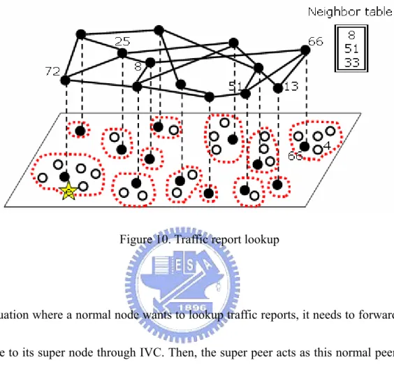
Figure 10. Traffic report lookup
In a situation where a normal node wants to lookup traffic reports, it needs to forward lookup message to its super node through IVC. Then, the super peer acts as this normal peer’s agent to complete the rest of the lookup process. When the target traffic report is found, it is first returned back to the agent. Later the agent transmit the target traffic report to this normal node though IVC.
Figure 10 illustrates how a traffic report lookup is performed. Node 4 is a normal node and it is managed by super node 66. When node 4 initiates a lookup to locate traffic report e, it forwards the lookup message to super node 66. Then super node consults it neighbor table and
select the node which is closet to the destination. The neighbor it forwards the lookup message to is super node 8. The lookup message is then forwarded to super node 25 and 72. Finally the target traffic report is found on super node 72. Super node 72 returns the target directly to super node 66, and super node 66 transmits the target to normal node 4 who initiates the lookup.
Chapter 5. Simulation
5.1. Simulation setting
The simulation process can be divided into two phases. In the first phase, we generate vehicle trace log file using micro-scope traffic simulator SUMO [22]. The simulation road topology is a 5x5 grid road network. Each road segment is defined as 500 m. The traveling speed of each vehicle is gradually changed according to local traffic condition. The maximum speed is not exceeded over 20 m/s. We simulate the system to run under different levels of traffic density. Details about traffic simulator parameter setting are listed in Table 3.
Road topology 5x5 2grid topology
km
Segment length 500m
Number of lanes 2 lanes per direction
Deceleration probability 2.6 / s2 m Acceleration probability 4.5 / s2 m Vehicle length 5m Maximum velocity 20 m/s
Traffic Density {1, 2,4} vehicle/km
Table 3. SUMO traffic simulator parameter setting
The radio communication range of each node is set to one kilometer. Two nodes are said to have direct wireless link between if they are within each other’s communication range. The neighbor table size is six and the small world random probability is set to 0.25. We simulate the system to run using different d-hop cluster formation. Details about system parameter setting are listed in Table 4.
IVC transmission range 1 km
Neighbor table size 6
Random probability 0.25
Super node selection period 2 seconds
Traffic condition broadcast period 2 seconds
Neighbor table update period 1 seconds
Traffic report lookup period 30 seconds
Traffic report lifetime 3 minutes
d-hop cluster formation [1, 2, 3]
Table 4. System parameter setting
We use the famous unstructured P2P overlay, Gnutella, as benchmark to examine the performance of our system. The simulation focuses on the traffic report lookup efficiency. We define two metrics to evaluate if our design supports efficient traffic report lookup: (1) lookup latency, (2) lookup message overhead. Simulation results show that the two-layer hierarchical
traffic information system does provide efficient traffic report lookup.
5.2. Simulation result
In Figure 11 and Figure 13, we study the performance of lookup latency in Gnutella and in our system design. The x-axis denotes the distance between the node who initiates traffic report lookup and the target road segment. The y-axis denotes the P2P overlay hop count per lookup. The phenomenon we observe is that in Gnutella the lookup hop count is not affected by distance between initiator and target location. In our design, the lookup hop count is larger than that in Gnutella; however, the difference in fairly small.
Lookup Latency 0 0.5 1 1.5 2 2.5 3 3.5 4 4.5 500 1000 1500 2000 2500 3000 3500 4000 4500 5000 5500 Small World (D = 1) Gnutella (D = 1) Small World (D = 2) Gnutella (D = 2) Gnutella (D = 4) Small World (D = 4) Distance (m) Hop count
Figure 11. Lookup latency in Small World overlay and Gnutella overlay under different traffic density
Lookup Latency 0 1 2 3 4 5 500 1000 1500 2000 2500 3000 3500 4000 4500 5000 5500 Small World (1d) Gnutella (1d) Small World (2d) Gnutella (2d) Distance (m) Hop count
Figure 12. Lookup latency in Small World overlay and Gnutella overlay under different d-hop cluster
In Figure 12 and Figure 14, we study the performance of lookup message overhead in Gnutella and in our system design. The x-axis denotes the distance between the node who initiates traffic report lookup and the target road segment. The y-axis denotes the P2P layer message overhead per lookup. The phenomenon we observe is that our system largely reduced message overhead because we rely on location based forwarding rather than scoped flooding for traffic report lookup.
Lookup Message Overhead 0 20 40 60 80 100 120 140 160 180 500 1000 1500 2000 2500 3000 3500 4000 4500 5000 5500 Small world (D = 1) Gnutella (D = 1) Small world (D = 2) Gnutella (D = 2) Small world (D = 4) Gnutella (D = 4) Distance (m) Message
Figure 13. Lookup message overhead in Small World overlay and Gnutella overlay under different traffic density
Lookup Message Overhead
0 20 40 60 80 100 120 500 1000 1500 2000 2500 3000 3500 4000 4500 5000 5500 Small world (1d) Gnutella (1d) Small world (2d) Gnutella (1d) Distance (m) Message
Figure 14. Lookup message overhead in Small World overlay and Gnutella overlay under different d-hop cluster
Chapter 6. Conclusion
In this paper, we propose a two-layer hierarchical decentralized P2P real-time road traffic information system which combines IVC and infrastructure-based wireless network. The system aims at providing accurate traffic reports and supporting efficient traffic report lookup. All vehicles share their capability and broadcast observed traffic condition through IVC. We take max-min d-cluster formation to select certain number of nodes as super nodes. These super nodes form a P2P overlay atop ad-hoc network to support traffic report lookup through infrastructure-based wireless network. With this overlay, lookup can be efficiently performed for drivers to retrieve real-time traffic reports.
Chapter 7. Reference
[1] Jun Luo, Jean-Pierre Hubaux, A Survey of Inter-Vehicle Communication [2] Wolfgang Kiess, Jedrzej Rybicki, Martin Mauve, On the nature of Inter-Vehicle
Communication
[3] http://www.inrix.com/techdustnetwork.asp
[4] http://www.gstproject.org/efcd/about.html
[5] Dr. Astrid Guhnemann, Stephan Lorkowski, Dr. Kai-Uwe Thiessenhusen, Ralf-Peter Schafer, Implications on City Traffic from Floating Car Data
[6] http://www.trafficmaster-online.com/index.asp
[7] Ioan Chisalita , Nahid Shahmehri, A Peer-to-Peer Approach to Vehicular Communication for the Support of Safety Applications
[8] Tamer Nadeem, Sasan Dashtinezhad, Chunyuan Liao, Liviu Iftode, TrafficView: Traffic Data Dissemination using Car-to-Car Communication
[9] Lars Wischhof, Andre Ebner and Hermann Rohling, Technical University of
Hamburg-Harburg Department of Telecommunications SOTIS - Self-Organizing Traffic Information System
[10] Lars Wischhof, Andre Ebner and Hermann Rohling, Information Dissemination in Self-Organizing Intervehicle Networks
[11] I. Stoica, R. Morris, D. Karger, M.F. Kaashoek, H. Balakrishnan, Chord: a scalable peer-to-peer lookup service for Internet applications
[12] A. Powstron, P. Duschel, Pastry: scalable, distributed object location and routing for large-scale peer-to-peer systems
[13] B. Y. Zhao, J. D. Kubiatowicz, A. D. Joseph, Tapestry: An infrastructure for fault-tolerant wide area location and routing
[14] S, Ratnaswamy, P. Francis, M. Handley, R Karp, S Shenker, a scalable content addressable network
[15] http://gnulella.wego.com
[16] Yatin Chawathe, Sylvia Ratnasamy, Lee Breslau, Nick Lanham, Scott Shenker Making Gnutella-like P2P Systems Scalable
[17] Alan D. Amis, Ravi Prakash, Thai H. P. Vuong Dung T. Huynh, Max-Min D-Cluster Formation in Wireless Ad Hoc Networks
[18] J. Kleinberg, Navigation in small world, Nature, 2000
[19] D. J. Watts (Ed.), Small Worlds: The Dymics of Networks between Order and Randomness, Princeton University Press, Princeton, NJ, 1999
[20] Brad Karp, H. T. Kung, GPSR: Greedy Perimeter Stateless Routing for Wireless Networks, MobiCom 2000
Scalable Location Service for Geographic Ad Hoc Routing
[22] Daniel Krajzewicz, Elmar Brockfeld, Jürgen Mikat, Julia Ringel, Wolfram Tuchscheerer, Christian Rössel, Peter Wagner, Richard Wösler, Simulation of modern Traffic Lights Control Systems using the open source Traffic Simulation SUMO