國立交通大學
電機資訊國際學位學程
碩士論文
用於 WiMAX 系統中以最大長方形為基礎之下
行鏈路資料叢集分配演算法
Maximum Rectangle-Based Down-Link Burst
Allocation Algorithm for WiMAX Systems
研究生:Jimmy Yau Zhong, 邱家俊
指導教授:李程輝博士
用於 WiMAX 系統中以最大長方形為基礎之下
行鏈路資料叢集分配演算法
Maximum Rectangle-Based Down-Link Burst
Allocation Algorithm for WiMAX Systems
研究生:邱家俊
Student: Jimmy Yau Zhong
指導教授:李程輝
Advisor: Tsern-Huei Lee
國立交通大學
電機資訊國際學位學程
碩士論文
A Thesis
Submitted to EECS International Graduate Program
National Chiao Tung University
in Partial Fulfillment of the Requirements
for the Degree of
Master
June 2011
Hsinchu, Taiwan, Republic of China
中華民國一百年六月
用於 WiMAX 系統中以最大長方形為基礎之下
行鏈路資料叢集分配演算法
研究生:邱家俊
指導教授:李程輝
國立交通大學
電機資訊國際學位學程
摘要
著名的行動通訊規格
802.16e WIMAX 在近年來開始被採用。因為其有著
高資料傳輸量和佈建的低成本,漸漸變成無線寬頻服務的主流方法。
WiMAX 使用 OFDMA 當作主要的傳輸方法。而從規格書上可知,一個資
料突衝需要被規畫成一個矩形才能放在以時間和頻率所組成的下載訊框裡,
但是如何設定矩形的形狀來減少浪費的空間並沒有詳細的介紹。近幾年不
少人提出了許多突衝規畫的演算法。在本篇論文裡,我們介紹了一個高效
率包裝的演算法,其能夠達到高傳輸資料量、減少未使用的槽、並且最小
化其規畫時所需的額外資訊。我們將提出的演算法和
eOCSA 還有 OBBP
這些之前提出來的演算法做比較。由數據結果可知我們的演算法較佳。
Maximum Rectangle-Based Down-Link Burst
Allocation Algorithm for WiMAX Systems
Student: Jimmy Yau Zhong
Advisor: Dr. Tsern-Huei Lee
EECS International Graduate Program
National Chiao Tung University
ABSTRACT
The IEEE 802.16e standard known as Mobile WiMAX has recently been introduced.
Because of the high data throughput and low cost deployment; it becomes one of the leading solutions for wireless broadband services. Mobile WiMAX makes use of
Orthogonal Frequency-Division Multiple Access (OFDMA) digital modulation
scheme as the transmission method. It is known from the standard that data burst in the
downlink subframe needs to be mapped into a time and frequency domain with a
rectangular shape, but how the data burst are placed in to minimize the wasted space
so that more data can be sent is not detailed. Many burst mapping algorithms have been proposed by researchers in these late years. In this thesis, we present an efficient
packing algorithm which achieves high throughput, reduces the number of unused
slots, and minimizes the mapping information overhead. We compare the performance
of our proposed algorithm with that of eOCSA and OBBP, high-performance packing
algorithms recently presented by other researchers. Numerical results show that our
Acknowledgement
This dissertation would not have been possible without the guidance and the help of
several individuals who in one way or another contributed and extended their valuable
assistance in the preparation and completion of this study.
First and foremost I want thank my parents, two sisters, and girlfriend for all their love, encouragement, and faithful support.
I would like to express my deepest gratitude to my advisor, Dr. Tsern-Huei Lee, for his
guidance, caring, and patience. Besides my advisor, I would like to thank Dr.
Yaw-Wen Kuo and Chi-Hsien Liu, whom were involved in this research work.
Thanks to my fellow lab mates and team members I have had the pleasure to work with. Special thank goes to Arleth Garth, a friend who stood by me through the good
and bad times.
Last but not the least; I also would like to make reference to Ms. Angel Yu, secretary
of the office of EECS International Graduate Program, for all the help and student
Table of Contents
Chinese Abstract………... i English Abstract……… ii Acknowledgement……….….... iii Table of Contents………..………… iv List of Tables………. v List of Figures………... vi Chapter 1: Introduction………. 11.1 OFDMA slots and bursts……….. 2
1.2 OFDMA Frame………... 4
Chapter 2: Problem Statement……….. 6
Chapter 3: Related Works………. 10
3.1 One Column Striping with non-increasing Area first mapping (OCSA)… 11 3.2 Enhanced OCSA (eOCSA) ………. 12
3.3 Orientation-Based Burst Packing (OBBP) ……….. 15
Chapter 4: Proposed Resource Allocation Algorithm………... 17
4.1 Maximum Rectangle-Based DL Burst Allocation………... 17
4.2 Enhanced Maximum Rectangle-Based DL Burst Allocation………. 25
Chapter 5: Performance Evaluation……….. 27
5.1 Simulation……… 27
5.2 Performance Analysis……….. 30
Chapter 6: Conclusion………... 35
References………. 36
List of Tables
Table 1. Fixed Versus Mobile WiMAX……….. 1
Table 2. Definition of OFDMA slot……… 4
Table 3. Ten random resource allocations example………... 23
List of Figures
Figure 1. Example of an OFDMA slot……….. 2
Figure 2. Example of an OFDMA frame structure in TDD mode……….... 5
Figure 3. IEEE 802.16 QoS architecture……….. 6
Figure 4. OCSA downlink burst mapping example………. 12
Figure 5. Example of resources allocated by OCSA algorithm and eOCSA Algorithm………... 13
Figure 6. Example of an orientation factor matrix by OBBP algorithm…………... 15
Figure 7. OBBP packing set rearrangement……….. 16
Figure8.Process for finding maximum rectangle area………... 18
Figure 9. Process for updating elements in set L……….. 22
Figure 10. Example of resources allocated by the proposed algorithm……… 24
Figure 11. Example of resources allocated by eOCSA and OBBP……… 25
Figure 12. Average efficiency vs. number of MS……….. 28
Figure 13. Average unused slots vs. number of MS……….. 29
Figure 14. Average over allocation slots vs. number of MS……….. 30
Figure 15. Illustration of the wasted slots of eOCSA algorithm……….... 33 Figure 16.Illustration of wasted space produced by mapping burst column wise…. 34
Chapter 1:
Introduction
Wireless communication systems have widely evolved in the recent years, making
WiMAX (Worldwide Interoperability for Microwave Access) one of the most
promising and popular networking infrastructures Broadband Wireless Access (BWA).
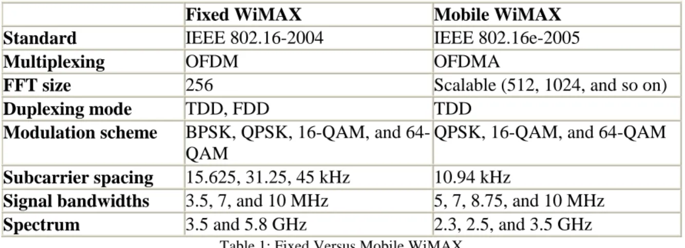
Each of the two WiMAX classifications, Fixed and Mobile, are based on a subset of
the IEEE 802.16 standards and are defined by the WiMAX forum. More specifically, Fixed WiMAX is based on the orthogonal frequency division multiplexing (OFDM)
physical layer of the 802.16-2004 specifications. While, Mobile WiMAX is based on
the orthogonal frequency division multiple access (OFDMA) physical layer of the
802.16e-2005 standard, which is a revision of the original Fixed WiMAX standard.
Table 1 shows a side-by-side comparison of the Fixed and Mobile WiMAX standards.
Fixed WiMAX Mobile WiMAX Standard IEEE 802.16-2004 IEEE 802.16e-2005
Multiplexing OFDM OFDMA
FFT size 256 Scalable (512, 1024, and so on)
Duplexing mode TDD, FDD TDD
Modulation scheme BPSK, QPSK, 16-QAM, and 64-QAM
QPSK, 16-QAM, and 64-QAM
Subcarrier spacing 15.625, 31.25, 45 kHz 10.94 kHz
Signal bandwidths 3.5, 7, and 10 MHz 5, 7, 8.75, and 10 MHz
Spectrum 3.5 and 5.8 GHz 2.3, 2.5, and 3.5 GHz
Within air interfaces defined in the IEEE 802.16 standard, OFDMA has shown to
reduce multi-path fading, while offering simultaneous access to multiple users to the
wireless medium. Longer transmission distances, higher data rates and better mobility
support are the main advantages of using this multicarrier technology.
The basic idea behind OFDMA is to divide the available frequency spectrum into several orthogonal carriers (often called subcarriers or tones). Due to this, inter-symbol
and inter-carrier interference are mitigated. Also, these subcarriers can be dynamically
assigned to different users for transmission, both in frequency and time dimensions.
This flexibility provides a way of boosting system performance, at the cost of
increasing the challenge of resource allocation.
1.1 OFDMA Slots and Bursts
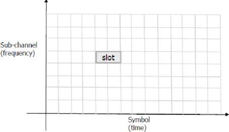
In the mobile WiMAX specification, an OFDMA slot is the minimum possible data
allocation unit. It is defined in two dimensions, one in time (symbol number) and the
other in frequency (subchannel number) as illustrated in figure 1.
The definition of an OFDMA slot depends on the subchannelization or subcarrier
permutation used:
Distributed permutation, logical subchannels are built from physically
distributed subcarriers along the available frequency spectrum. This channel
diversity reduces the effect of fast fading on mobile environments. Also, the
averaged Signal-to-Noise-Ratio (SNR) is practically the same for all subchannels (from the point of view of one user), so all subchannels are equally
adequate for all transmitters. The subchannelizations based on distributed
permutation includes DL PUSC (Downlink partial usage of subchannelization),
DL FUSC (Downlink full usage of subchannelization), and UL PUSC (Uplink
partial usage of subchannelization).
Adjacent permutation, subchannels are built from physically adjacent
subcarriers. This leads to user diversity, due to the fact that users will get very
different SNR measures for different subchannels. The subchannelization based
on adjacent permutation includes DL AMC (Downlink adaptive modulation and
coding) and UL AMC (Uplink adaptive modulation and coding) subchannels.
In the DL FUSC, each slot is composed of a subchannel and an OFDMA symbol. For
the DL PUSC, one slot is one subchannel by two OFDMA symbols. And for the UL PUSC each slot is composed of a subchannel by three OFDMA symbols. However, in
the case of the DL/UL AMC, one slot is one subchannel by three OFDMA symbols.
For all the cases, an OFDMA slot contains 48 data subcarriers. Table 2 lists a
Subchannelization scheme Number of subchannels per slot Number of symbols per slots DL FUSC 1 1 DL PUSC 1 2 UL PUSC 1 3 DL/UL AMC 1 3
Table2: Definition of OFDMA slot
The OFDMA symbols generated out of a user terminal are mapped into a
two-dimensional data block called burst. Burst, in general terms, is a data region that is a
two-dimensional data block consisting of a group of contiguous OFDMA slots.
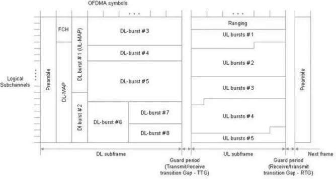
1.2 OFDMA Frame
The OFDMA frame structure is composed of “DL/UL data bursts”, which carry user data traffic; “Preamble”, which is used by the PHY layer for synchronization and
equalization; “Frame control header (FCH)”, which describes the length of the
MAP message, the repetition encoding, and the channel coding applied to the DL-MAP; “DL/UL MAPs”, which contains the number of burst and their locations (offset
and lengths in time-frequency domain); “Channel quality information channel (CQICH)”, which is used for DL CINR report and MIMO mode selection feedback; “ACK channel”, which provides feedback for DL HARQ; and “Ranging subchannel”,
which is allocated to MSs (Mobile Stations) for initial ranging, periodic ranging,
handover ranging, and bandwidth request.
Mobile WiMAX employs Time Division Duplex (TDD) technology, where the same
period, with a gap (TTG & RTG) following each period. Frequency Division Duplex
(FDD) technology can also be supported. FDD use different frequencies for uplink and
downlink. Figure 2 illustrate an example of OFDMA frame structure for TDD.
Chapter 2:
Problem Statement
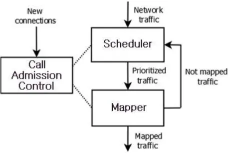
In Mobile WiMAX networks, the BS is responsible of performing most of the system
decisions. From the perspective of QoS, these decisions include: call admission control,
scheduling and resource allocation as shown in figure 3.
Figure 3: IEEE 802.16 QoS architecture
New connections are accepted or rejected by the Call Admission Control (CAC) based on the available system capacity, in order to assure that the presence of a new
connection will not impair the QoS requirements of the existing ones. After
connections are accepted, the network traffic must be properly prioritized according to
a certain scheduling policy. This scheduling policy should be able to guarantee that
process may be needed, which is resource allocation. Network traffic must be logically
mapped into a time-frequency matrix before it is actually transmitted through the
wireless medium. After this step is done, some resource request may remain unmapped,
so it must be returned to the scheduler for its transmission in a later frame.
Although the scheduler is the main factor affecting QoS fulfillment, the resource allocation step may impair it. This can happen if the prioritization established by the
scheduler is not fully respected. Also, a bad resource allocation policy may severely
reduce the utilization of the spectral resources.
A burst is an allocation for transmitting data aimed to one or more MSs. Some
restrictions are imposed to the way the resource allocator maps the scheduler traffic. First, data from different MSs being sent in a burst must be transmitted using the same
Modulation and Coding Scheme (MCS). Depending on the channel quality perceived
by a certain user, it may be needed or preferred to use an MCS or another. For
example, an SS which is far away from the BS may need to use a reliable scheme
(such as QPSK-½); while another one with good channel conditions would use a more
efficient scheme (such as 64-QAM-¾). Obviously, if two MSs will transmit using the
same MCS, they will also be able to use the same burst.
The shape of a single burst is mandatorily rectangular and cannot overlap each other.
Burst dimension is specified in the DL-MAP IE with its symbol offset, subchannel
In order to design an efficient DL mapping algorithm, there are some factors to take
into account, which are MAP overhead, unused slots, over-allocated bursts, and QoS
preservation.
When a new burst is inserted into the frame, the respective IE must be added to
DL-MAP. Obviously, the MAP uses slots which could be otherwise used to transmit data. This means that there is a certain MAP overhead directly proportional to the number of
bursts in a frame. Also note that to one MS, multiple bursts can be assigned. However,
such an allocation increases the DL-MAP overhead. It is also possible to put the data
of multiple MSs into a single burst. Thus, reducing the number of bursts may leave
more slots for sending data.
Due to the rectangular shaping restrictions, it is possible that some slots of the frame
may not get assigned to any burst. These unused slots are considered as a waste of
bandwidth, so the mapper should minimize its number. On the other hand, some slots known as “over allocated” may be also internally wasted in a burst because more slots
than required are given to a MS to fulfill with the rectangular shape of the burst. In this
work, we assume that only one burst is allocated to each MS and a burst is never
shared by multiple MSs.
The overall performance of the system will depend on the combined efficiency of the
QoS scheduler and DL-MAP packing algorithm which try to maximize the radio
In a WiMAX system, QoS provisioning depends not only on the QoS scheduler but
also on the DL-MAP packing algorithm. Because of the rectangular shape of the bursts
in the WiMAX downlink subframe, it could happen that no solution is found that can
pack all the data in rectangular bursts with the available capacity. Moreover, a packing
algorithm should be able to adapt to packing constraints and still be reasonably
efficient. Because of design considerations some kind of rectangular shapes or positions in the WiMAX frame might be preferred, e.g., allocations in the subchannel
dimension due to power consumption reasons.
A common length of a WiMAX frame is 5ms considering both downlink and uplink
subframes. In this case, 5ms is the maximum time that a WiMAX base station has for
taking decisions on a per frame basis, in order to maximize performance. Thus, the computational load required by both the QoS scheduler and DL-MAP packing
algorithm should be kept as low as possible to meet this tight deadline without
Chapter 3:
Related Works
In this section, we briefly review some of the other burst mapping algorithms for
Mobile WiMAX. Basically, the downlink scheduler generates a set of requests to be
allocated, which is determined based on current backlog, QoS parameters (delay and
throughput), and available capacity. Then, a burst mapping algorithm allocates these
requests in a rectangle form.
Several algorithms have been proposed recently to address the burst mapping problem
[2]-[13]. For example, in the algorithm proposed by Ohsekiet. al. [2], data of multiple MSs having same physical mode are placed into “bucket”, a defined resource unit in
the vertical direction (subchannels). Multiples buckets are assigned in case a single
bucket is not sufficient to contain the data. Buckets with same length and physical
mode are put together to form a burst.
In the algorithm presented in [6], separate queues are provided for delay tolerant users
and delay sensitive users. Delay tolerant users are not served until they have sufficient
data to fill an entire row of slots in the time domain. If a delay sensitive user is picked
by the scheduler, as many slots as needed are allocated to serve all its queued data.
the user with larger request that can fit into this space is mapped. This algorithm may
end up needing more rows than available and some signaling overhead.
Work in [7], provides a study of the impact of the performance of a WiMAX DL-MAP
packing algorithm on the overall system performance and set an upper bound on the
maximum achievable resource usage by a DL-MAP packing algorithm. The OCSA, eOCSA and OBBP algorithms proposed in [7]-[10], respectively, are related to our
work and, therefore, will be reviewed in depth.
3.1 One Column Striping with non-increasing Area first mapping (OCSA) [7]
The One Column Striping with non-increasing Area first mapping (OCSA) algorithm
consists of three steps. First, a set of resources to be allocated is obtained from the downlink scheduler, based on its demand, QoS parameters (delay and throughput) and
available capacity. Then, the algorithm will sort this set of resources in the descending
order.
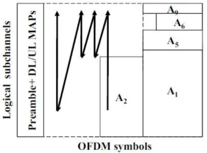
In the second step, the resources to be allocated are mapped into the DL subframe
from right to left and from bottom to top as shown in figure 4. The algorithm selects
the largest resource to map and checks if it can fit into the available space in the subframe. Because a burst can have many possible width-height combinations [7], the
algorithm selects the combination with the smallest width or in a second case, the
Figure 4: OCSA downlink burst mapping example
In the third step, the OCSA algorithm will search for the largest resource to be
allocated that can fit into the space (or strip) left on top or above the burst mapped in
the previous step 2. In this step, the combination with the least height is selected. This
process is repeated until no further allocation can be done in the strip or if there is no
resource that can fit. After this, the algorithm moves leftward to fill the remaining
empty columns in the DL subframe and repeats from step 2. Remaining resources after the algorithm terminates are sent back to the scheduler to be mapped in a future frame.
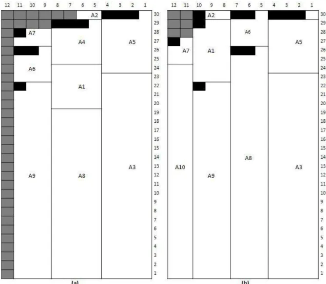
Figure 5 (a) shows an example of resources allocated by the OCSA algorithm. In this
example, the set of resources to be allocated are {92, 76, 65, 48, 25, 20, 17, 10, 5, 2}.
3.2 Enhanced OCSA (eOCSA) [7]
This algorithm is very similar to its predecessor (OCSA) [7]. The resources to be
allocated are also mapped into the DL subframe from right to left and from bottom to top, but this time, a few enhancements are added to make it more efficient.
Figure 5: Example of resources allocated by (a) the OCSA algorithm and (b) the eOCSA algorithm
Same as in the OCSA algorithm, the first step is to sort in the descending order the set
of resources to be allocated that were obtained from the downlink scheduler. In the
second step, the eOCSA algorithm selects the biggest resource to be allocated and
calculates W*A H/ and H*A W/ * , where A is the area of the resource to be
allocated, H is the maximum height that can be used for allocation, and W*andH* are,
In the third step, the algorithm looks for the next largest resource to be allocated that
can fit into the space left on top of the burst mapped in the previous step 2. But here,
the widths of all following bursts allocated in the strip are fixed to that of the burst
allocated in the previous step. In other words, the height of each burst allocated in the
strip is computed as the smallest integer greater than or equal to the area of the burst
divided by the fixed width. This process is repeated until no space can be allocated or if there is no resource that can fit into this space. After this, the algorithm moves
leftward to fill the remaining empty columns in the DL subframe and repeats from step
2. Figure 5(b) shows an example of the eOCSA algorithm handling the same resources
allocated by the OCSA algorithm illustrated in Figure 5(a). One can see that eOCSA
has a better performance than OCSA for this example. The OCSA algorithm leaves 38
empty slots and over allocates 10 slots. The numbers for the eOCSA algorithm are 6 and 11, respectively.
Note that most of the bursts allocated by the OCSA and eOCSA algorithms have the
least widths, which implies that the active time and consequently, the energy
consumption, of each MS is minimized. Besides, by considering mapping the larger
resources first, utilization of downlink resources can be maximized. Our proposed
algorithm presented in the next chapter also adopts these ideas. However, we do not restrict allocation of resources in a strip, after it is created. Instead, whenever a burst
is to be allocated, our algorithm finds the largest rectangle in the remaining
3.3 Orientation-Based Burst Packing (OBBP) [10]
The principle of OBBP algorithm is to group up the resources based on the orientation
factor (OF) and pack the bursts of each group in column-wise or row-wise in the DL
subframe. The algorithm divided into three stages. First stage is a pre-packing stage to
prepare and classify the requests. A process called OF calculation will give the
possible dimension for each rectangle. For example, given a set of resource request B = {10, 6, 8, 5}, the orientation factors for this set will be {10x1, 1x10, 2x5,5x2}, {6x1,
1x6, 3x2, 2x3}, {8x1, 1x8, 4x2, 2x4}, and {5x1, 1x5}. If a request has one or more
OFs out of the DL subframe range, those out of range OFs are removed. And if the
request has no OF within the DL subframe range, the size of this request is increased
by 1 and OF calculation is performed again until at least one within range OF is found.
In the second stage, the resources are classified according to their common number of
symbols (vertically) or subchannels (horizontally) in a matrix generated from the OFs
obtained on the first stage. Figure 6shows an example of the OF matrix produced using
Then, packing sets are selected by calculating the maximum sum of the elements in
each columns or rows of the OF matrix. From this set, bursts are going to be placed in
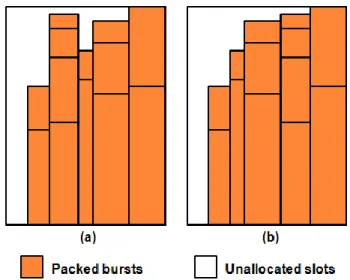
a descending order. Later, the algorithm rearranges the packing sets by sorting them in
descending order so that burst packing starts from the bottom-right corner and grow in
the two dimensions, leaving the unallocated slots at the top-left corner, as shown in
Figure 7.
Figure 7: OBBP packing set rearrangement (a) Before and (b) After
In the third stage, overlapped rectangles with its maximum possible dimensions are
made with the unallocated slots. The remaining set of resources is sort in descending
order and an optimum rectangle for the first resource that has the minimum difference between the rectangle area and burst size is selected for packing remaining burst.
Chapter 4:
Proposed Resource Allocation
Algorithm
4.1 Maximum Rectangle-Based DL Burst Allocation
This section presents the proposed two-dimensional rectangular burst mapping algorithm. For convenience, define the coordinate of the bottom-right corner of the
downlink subframe as (1,1). Assume that there are s slots and c subchannels in the downlink subframe. Let Ωbe the set of all slots in the subframe and Ω = {(x,y)|1 ≤ x
≤ s, 1 ≤ y ≤ c }. The algorithm allocates slots to a request iteratively, and U denotes the set of current unallocated slots. In each iteration, a rectangle r in U is allocated to a selected request. r is denoted by [(x0,y0); w, h] where (x0,y0), w, and h are its bottom-right corner, the width , and the height, respectively. Initially, U = Ω and the request set with N elements is denoted by Ai= {𝐴𝑖}𝑖−1𝑁 .The proposed algorithm consists of
three phases as follows.
First phase: finding max rectangle
In this first phase, we will basically look for the rectangle which gives the maximum
area in U that will be used to allocate the burst and will be denoted by R= [(x0,y0); W,
In order to find the largest rectangle in U, a set L ⊂ Ω is maintained during the mapping process, which is used to record the bottom-right corners of candidate
rectangles. It is clear that, initially, we will only have L = {(1,1)}and it is obvious that after mapping the first burst, there could be many possible rectangles.
Now, the question is: how can these bottom-right corners will help to find the largest
rectangle? From these bottom-right corners, we will extend to the left and up all the
possible until there is no more unallocated space that can be used, and among these
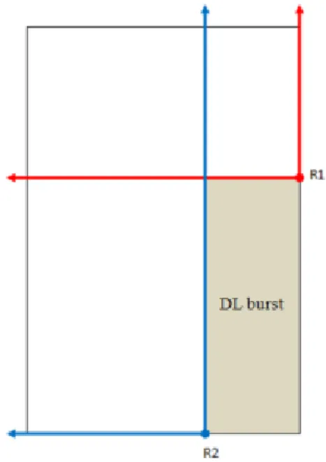
created rectangles, the one with the maximum total area is selected to allocate the burst.
Figure 8, illustrates an example of the process for finding the maximum rectangle area for burst allocation, where we can see the resulting two candidate rectangles after the
first burst is allocated, a red one and a blue one, denoted as R1 and R2 respectively.
Notice that the bottom-right corners of each rectangle, which are the elements in L, are
also shown. And that the blue rectangle gives the maximum area for allocation
between these two rectangles.
The following pseudo code is the procedure used on the first phase to find the largest
rectangle in U.
1 1 2 2
Find the maximum rectangle in
Given {( , ), ( , ), , ( , )} [ 1, 1] 0 [ 1] 0 [ 1] 0; [ 1] 0 For 1 to do{ For to 1 do{ If ( , ) then [ , n n w h U L x y x y x y height s c area n R n R n i s j c i j U height i ] [ , 1] 1 else [ , ] 0 } } For 1 to do{ ( , ) ( , ) 0 While ( , ) do{ min( , [ , ]) ( , ) ( 1, ) If [ ] then{ [ ] [ ] temp temp k k temp temp temp temp temp temp temp temp
temp k w j height i j height i j k n x y x y w h c x y U h h height x y x y x y w x x area k w h area k w h R k [ ] } } If [ ] [ 1] then _ e [( , ); [ ], [ ]]
/ /Record the maximum rectangular } return _ e h k k w h w R k h area k area k Max r c x y R k R k Max r c
Second phase: burst allocation
In this second phase, after finding the maximum rectangle, the selection of the largest
element in A for mapping, say Ak, such that Ak ≤ W∙H is the next step, or in other words, the largest resource request that can fit into this maximum rectangle is selected
for mapping. Remember that W and H stand for the maximum rectangle‟s width and height respectively.
Once the selected the resource request for mapping, the dimension of the burst is
defined. Set its width equal to w, where w has the minimum possible width and thus, minimizing MS power consumption. According to the following equation (H stands for the maximum rectangle‟s height):
w = 𝐴𝑘/ 𝐻
Set its height, denoted as h as follows:
h = 𝐴𝑘/ 𝑤
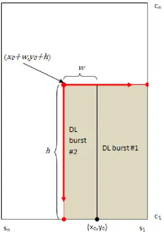
After the dimension for the burst is defined, allocation of the burst or rectangle r = [(x0,y0);w, h]for request Ak to the downlink subframe begins. The location of the burst inside the downlink subframe will depends on the maximum rectangle. The bursts are
The algorithm terminates if there is no resource request that can fit into the available
space of the selected rectangle or we can say that, when no such Ak exists, the algorithm ends.
Third phase: update L
Now that the burst has been placed into the downlink subframe, in this third phase,
resource request Ak is removed from the set of resource request A and the set of
bottom-right corners L needs to be updated, so that the maximum rectangle can be found properly once the algorithm goes back to the first phase.
In order to update L, assume that r = [(x0,y0); w, h]is allocated in the second phase.
The set of bottom-right corners L is updated as follows. First, any element (𝑥, 𝑦) ∈ (𝐿 ∩ 𝑟)is removed out ofL. In simple words, the bottom-right corner of the just allocated burst is removed from L. Second, search for possible candidates from (x0
+w,y0+h)to the right. Any element (x,y0+h) is added to set L if there existsℎ′ > 0
such that [ 𝑥, 𝑦0 + ℎ); 𝑥0 + 𝑤 − 𝑥, ℎ′] ⊂ 𝑈and[ 𝑥 − 1, 𝑦
0 + ℎ); 𝑥0 + 𝑤 − 𝑥 + 1, ℎ′] ⊄
𝑈.Then the algorithm, again search for possible candidates, but this time, from (x0
+w,y0+h) to bottom. Any element(x0+w,y)is added to L if there exists𝑤′ > 0 such
that[ 𝑥0 + 𝑤, 𝑦); 𝑤′, 𝑦0 + ℎ − 𝑦] ⊂ 𝑈 and [ 𝑥0 + 𝑤, 𝑦 − 1); 𝑤′, 𝑦0 + ℎ − 𝑦 + 1] ⊄ 𝑈.
Continuing the previous example in figure 8, figure 9 illustrates how this third phase works. Notice that a new burst was allocated. The algorithm start from point (x0 +w,y0
+h) following each arrow directions, looking for the maximum length that can be reached and are this points were the bottom-right corner (the others two red points on
figure 9) are defined as elements in L. The figure also shows that any element already in L is skipped to avoid duplication.
Because the maximum rectangle is used for allocation in each iteration, we name the
proposed algorithm the maximum rectangle-based DL burst allocation algorithm.
Figure 9: Process for updating elements in set L
Before leaving this subsection, we present an example to explain the operation of the
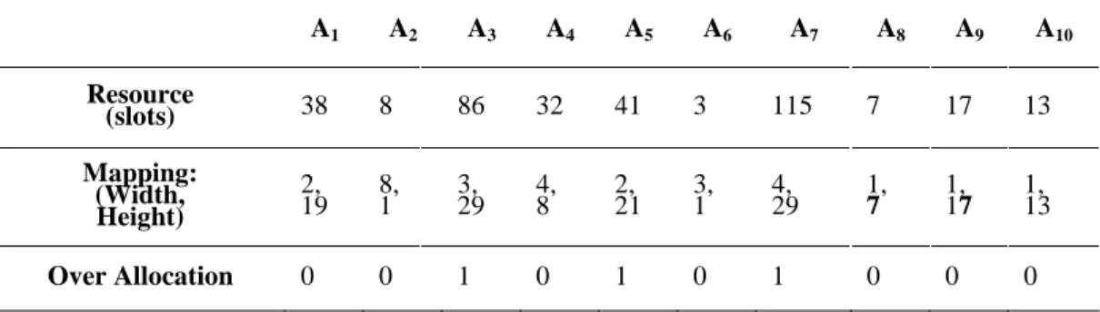
There are ten MSs with request set A as shown in Table 3 and the sum of all requests is equal to 360. A1 A2 A3 A4 A5 A6 A7 A8 A9 A10 Resource (slots) 38 8 86 32 41 3 115 7 17 13 Mapping: (Width, Height) 2, 19 8, 1 3, 29 4, 8 2, 21 3, 1 4, 29 1, 7 1, 17 1, 13 Over Allocation 0 0 1 0 1 0 1 0 0 0
Table 3: Ten random resource allocations example
Initially, we have U = Ω and L = {(1,1)}. Consider the first iteration. The largest rectangle in U is [(1,1);12,30] and the largest request smaller than 12x30=360 isA7 =
115. According to the second phase, the rectangle [(1,1);4,29] is allocated toA7. The
over allocation (shown in black) would be of only 1 slot. And the set L is updated as L = {(1,30),(5,1)}.
In the second iteration, the maximum rectangle in U is [(5,1);8,30] and the largest one in the updated request set smaller than 8x30=240 isA3= 86. According to the second
phase, the rectangle [(5,1);3,29] is allocated toA3 with 1 slot of over allocation. The
set L is updated again, giving L = {(1,30),(8,1)}.
In the third iteration, [(8,1);5,30] is the maximum rectangle in U and is used for allocation. The rectangle [(8,1);2,21] is allocated to A5 with 1 over allocated slot. After
The algorithm is executed for six more iterations to sequentially allocate rectangles to
requests A1, A4, A9, A10, A2, and A6.
The result is shown in Figure 10. For this example, there is no allocation to request A8.
The total number of over allocated slots is 4 and the total number of unused slots is 3.
The packing efficiency (percentage of slots used) of the proposed algorithm is 98.06% with over allocated slots and unused slots being counted as wasted. Figure 11
illustrates the packing results for eOCSA and OBBP using the same ten random
resource allocations used in the previous example of the proposed algorithm.
Figure 11: Example of resources allocated by eOCSA and OBBP
4.2 Enhanced Maximum Rectangle-Based DL Burst Allocation
Slight changes have been made to the maximum rectangle-based burst allocation
algorithm while remaining quite similar. Furthermore, we no longer select only the
maximum rectangle, but consider all possible rectangles to map the request in order to
reduce over allocated slots.
rectangles within the unallocated spaces of the downlink subframe. But, the selection
of the rectangle with the highest total area is omitted in this phase of the enhanced
version of the algorithm.
Moving into the second phase, once selected the largest request from A, say Ak. The
dimension of the burst for request Ak is computed for each of the candidate rectangles
found in the previous first phase. After this has done, the algorithm will proceed to
evaluate the amount of over allocation slots that the burst will have in each of these
candidate rectangles. So, the one with the least over allocation slots will be selected for
the mapping. Then, the mapping of the burst and the rest of the algorithm will be done
in the same way as the original version of the algorithm.
It is worth to mention that while considering all possible rectangles of the first phase,
in some cases, the request may not fit into a rectangle and so, this rectangle is
discarded. And because for each rectangle, the burst will have different dimensions,
allowing the algorithm to select the rectangle that will result in less over allocation
slots for the burst. In case there are two candidate rectangles, which gives the same
amount of over allocation slots, the candidate rectangle with the largest total area will
be selected.
The enhanced maximum rectangle-based burst allocation algorithm results, not only in
Chapter 5:
Performance Evaluation
In this chapter, the performance of the proposed algorithm and its enhanced version
will be discussed and from now on, the two algorithms will be referenced as
MaxRectangle and eMaxRectangle respectively. In order to study the performance of
MaxRectangle and eMaxRectangle algorithms, simulations for these two algorithms,
eOCSA and OBBP has been performed and compared. Notice that OCSA was not
included into the comparison due to the fact that its enhanced version, the eOCSA algorithm performs better.
5.1 Simulation
For performance evaluation, the total number of unused slots, over allocated slots, and
packing efficiency is studied. The over allocations and unused slots are averaged and
normalized over 10,000 trials.
Simulation parameters used for each algorithm where the same and are resumed on
Table 4, which are from the suggestions of the WiMAX forum. Resource requests
were generated randomly with the sum of all requests equal to 1230 slots or 360 slots, as a constraint. We assume each MS needs only one burst.
Parameter Value
Frame length 5 ms
Channel BW 10 MHz
Permutation scheme PUSC
Number of subchannels 30
DL subframe 12 slot columns
Total number of slots per DL subframe 30 x 12 slots
Simulation time 10,000 frames
Table 4: System simulation parameters
Figure 12 shows the average packing efficiency, which is defined as allocated slots
divided by total slots per frame, of all schemes to different number of mobile stations
per frame. We can see that the proposed algorithms achieve higher packing efficiency.
Figure 12: Average efficiency vs. number of MS
6 8 10 12 14 16 18 20 22 24
0.85 0.9 0.95 1
Number of Mobile Stations
E ff ic ie n c y ( a llo c a te d s lo ts / t o ta l s lo ts ) eOCSA MaxRectangle eMaxRectangle OBBP
Figure 13 illustrates the impact of the number of mobile stations on average unused
slots per downlink subframe. The average number of unused slots for the proposed
algorithms is smaller than that for eOCSA and OBBP. eOCSA wastes more slots
because of its third step, and OBBP algorithm allocate the resource into free rectangle
spaces in their third stage, resulting in fewer shapes that can be choose.
Figure 13: Average unused slots vs. number of MS
Figure 14 indicates the average over allocated slots of all schemes to different number
of mobile stations per frame. The eMaxRectangle select the appropriate waste less rectangle to allocate. Thus the average number of over allocation slots for
eMaxRectangle is lower than that for MaxRectangle and eOCSA. Besides that, is
acceptable that OBBP results in less average over allocation slots than eMaxRectangle,
6 8 10 12 14 16 18 20 22 24 0 10 20 30 40 50 60
Number of Mobile Stations
N u m b e r o f u n u s e d s lo ts eOCSA MaxRectangle eMaxRectangle OBBP
because this last one has the lowest average number of unused slots, but still the
proposed algorithm has the best packing efficiency.
Figure 14: Average over allocation slots vs. number of MS
In this chapter, the simulation results shows that the proposed algorithm indeed
performs better than its competitors, but the reasons of this efficiency will be
explained in details through some examples in the following section.
5.2 Performance Analysis
In this section, more than presenting the reasons of the better performance of the
proposed algorithm against the ones compared with, an analysis of the things that
6 8 10 12 14 16 18 20 22 24 1 2 3 4 5 6 7 8
Number of Mobile Stations
N u m b e r o f o v e r a llo c a ti o n s lo ts eOCSA MaxRectangle eMaxRectangle OBBP
allows a downlink packing algorithm to achieve a high utilization of the resources is
presented.
Sorting the MSs resource request in decreasing order before packing will definitely
impact on how efficient the resource in the downlink subframe is going to be used by
the packing algorithm because is more easier to fit small burst into the remaining spaces on the subframe, specially when this is the last remaining burst that need to be
packed and on the contrary, a larger burst not packed will lead to more unused slots.
But, special care has to be taken when designing a packing algorithm since operations
like ordering the data to be packed by decreasing size might result in a larger
utilization of the WiMAX downlink subframe resources but not necessarily in a larger throughput. MSs with better channel conditions will have a better MCS and thus, one
slot can transmit more data than one MS with lower MCS.
So, in order to achieve higher throughput and an efficient use of the resources in the
downlink subframe, it is advised to pack based on the amount of slots the MS require
and the total data that would be packed. For example, pack the burst with the highest
amount of data to transmit first, in case of a tie, refer to the amount of slots assigned, selecting the highest. Consider the following scenario, a small burst with higher MCS
and a large burst with lower MCS and less data to transmit, in this case is better to
pack the smaller in order to achieve higher throughput but in some cases this might
Obviously, the reason why the proposed algorithm performs better than eOCSA and
OBBP is the way of allocating the burst into the downlink subframe. Because bursts
are required to have a rectangular shape, the proper dimension of it is another
procedure that needs our attention while designing an efficient packing algorithm.
A burst can have different dimensions with different resulting over allocation slots or no over allocation at all. Then, selecting the dimension with none or less over
allocation should be the best in order to maximize the utilization of resources in the downlink subframe. It‟s believed that packing efficiency of the proposed algorithm
could increase a little more if applied, but was not considered to lower the complexity
of the algorithm. Instead, like in the eOCSA algorithm, most of the bursts allocated by
the algorithm have the least widths, which imply that the active time and consequently, the energy consumption of each MS is minimized.
While allocating bursts vertically or column wise simplifies things, it may results in
some disadvantages. The problem of packing burst column wise or row wise is that,
for example, in eOCSA all bursts in a common column will have the same width, and
so, the burst will only adopt one dimension. For this reason, some burst may result in
more over allocated slots than others. Besides, the whole column can possibly not be filled completely with burst, given the reason that there‟s no resource request that can
fill the spaces left. And this will apply for all the columns of burst, resulting into more
unused spaces, as shown on figure 15. Notice that, only the first column of burst,
Figure 15: Illustration of the wasted slots of eOCSA algorithm
If we forget about how eOCSA compute its burst dimension, burst A5 dimension (on
figure 15) could have been set with height equal to 4 and width equal to 2, resulting in only one over allocation slot, and if we didn‟t have this column width limits, the space
left could have been used to place other burst more flexibly. Figure 16 illustrates the
above mentioned; where the white area is the unallocated slots and the over allocated slots are shown in black.
Figure 16: Illustration of wasted space produced by mapping burst column wise
Like in eOCSA algorithm, OBBP can also have unused slots on the top of each
columns of burst. OBBP sort their columns in descending order, so that all unallocated
spaces will be located to the left and top of the downlink subframe, please refer back
to figure 7 on chapter 3. By doing this, all unused slots will be together, making it
easier to place a burst that could possibly not fit without this. Then, they try to allocate the burst in a selected rectangle that result with the least over allocated slots, but
because they still continue with the use of their OFs, the dimension of some burst left
cannot be placed into some of these rectangles, which is the reason why OBBP results
Chapter 6:
Conclusion
This work presents a novel downlink burst allocation algorithm for IEEE 802.16e
Mobile WiMAX networks. Similar to eOCSA, the proposed algorithm meets the
rectangle shape allocation constraint, achieves high throughput by considering
mapping the larger resources first, and optimizes energy consumption at MS by
minimizing its receive time. The basic idea of our proposed algorithm is to find the
maximum rectangle in the un-allocated space for allocation in each iteration. An efficient method for finding the maximum rectangle is provided. Furthermore, the
algorithm is enhanced to improve the efficiency. The performance of the proposed
algorithm is compared with that of eOCSA and OBBP. Simulation results show that
the proposed algorithm, enhanced maximum rectangle-based burst allocation
algorithm, outperforms eOCSA and OBBP.
Mapping bursts column wise or row wise can reduce the complexity of packing
algorithms but may not result in the best efficient way of packing. A packing
algorithm that strictly tries to maximize the utilization of the frame can result in a
violation of the agreed QoS guarantees or unfair distribution of the resources.
Therefore, a trade-off between radio resource usage maximization, QoS and fairness
References
[1] Byeong Gi Lee and Sunghyun Choi, “Broadband Wireless Access and Local Networks: Mobile WiMAX and WiFi”, Artech House, 2008.
[2] T. Ohseki, M. Morita, and T. Inoue, “Burst Construction and Packet Mapping Scheme for OFDMA Downlinks in IEEE 802.16 Systems,” Proceedings of
IEEE Global Comunications Conference (IEEE GLOBECOM), 2007.
[3] Y. Ben-Shimol, I. Kitroser, and Y. Dinitz, “Two-dimensional mapping for wireless OFDMA systems,” in IEEE Trans. Broadcasting, vol. 52, no. 3, pp.
388-396, Sept. 2006.
[4] Bacioccola, C. Cicconetti, L. Lenzini, E.A.M.E. Mingozzi, and A.A.E.A. Erta, “A downlink data region allocation algorithm for IEEE 802.16e OFDMA,” in
Proc. Int. Conf. Information, Comm. and Signal Processing, 2007, pp. 1-5.
[5] F. Clautiaux, J. Carlier, and A. Moukrim, “A new exact method for thetwo-dimensional orthogonal packing problem,” in European Journal Operational
Research, vol. 127, pp. 1196-1121, Dec. 2007.
[6] Patrick Hosein, “Cross-Layer Design for Data Burst Construction in the
Downlink of IEEE 802.16 Systems”, Proceedings of IEEE Global
Comunications Conference (IEEE GLOBECOM), 2008.
[7] X. Perez-Costa, P. Favaro, A. Zubow, D. Camps and J. Arauz, “On the
Networks”, in Proc. IEEE Consumer Communications and Networking
Conference (CCNC 2008), pp. 890-896, 2008.
[8] So-In, R. Jain, and A. Al-Tamimi, “OCSA: An algorithm for Burst Mapping in IEEE 802.16e Mobile WiMAX Networks”, Proceedings of the 15th
Asia-Pacific Conference on Communications. (APCC 2009), Oct. 2009.
[9] So-In, R. Jain, and A. Al-Tamimi, “eOCSA: An Algorithm for Burst Mapping with Strict QoS Requirements in IEEE 802.16e Mobile WiMAX Networks”,
Proceedings of the 2nd International Conference on Computer and Automation
Engineering (ICCAE 2010), Feb. 2010.
[10] Eshanta, M. Ismail, K. Jumari, “An efficient burst packing algorithm
forOFDMA systems”, Proceedings of the 2nd International Conference on
Computer Technology and Development (ICCTD), Nov. 2010.
[11] K.-P. Shih, C.-T. Chiang, T.-H. Hsieh, and Y.-H. Lin, “A downlink resource management scheme in IEEE 802.16 OFDMA-based system”, Proceedings of
the Workshop on Wireless, Ad Hoc, and Sensor Networks, Sep. 2008.
[12] C. Cicconetti, L. Lenzini, A. Lodi, S. Martello, E.Mingozzi, M. Monaci, “Efficient Two-dimensional Data Allocation in IEEE 802.16 OFDMA”,
Proceedings of IEEE IEEE International Conference on Computer Communications (IEEE INFOCOM), 2010.
[13] Panagiotis G. Sarigiannidis, Malamati D. Louta, Periklis Chatzimisios, “A
Novel Fair Mapping Scheme for IEEE 802.16Downlink Sub-Frame”,
Proceedings in International Congress on Ultra Modern Telecommunications
Biography
Jimmy Yau Zhong was born in July1, 1985 in Panama City, Panama. Jimmy entered
Technological University of Panama as an undergraduate in 2004 after completing his
elementary and high school studies at Saint George International School of Panama. In
2008, he completed his Bachelor of Computer Networks. Later that same year, he