Optical head design using prism-type holographic optical
element for small form factor applications
Hsi-Fu Shih*
a, Yuan-Chin Lee
b, Yi Chiu
c, and Gung-Ding Lin
aa
Dept. of Mechanical Engineering, National ChungHsing Univ.,
250 Kuo-Kuang Rd., Taichung, 402 Taiwan, R.O.C.
b
Electronics and Optoelectronics Research Labs., Industrial Technology Research Institute
cDept. of Electric & Control Engineering, National ChiaoTung Univ.
ABSTRACT
This paper presents an optical head design that minimizes the component number and miniaturizes the head dimension by using a novel reflective prism-type holographic optical element (PT-HOE) for the next-generation high-density blue-light system with small form factor (SFF). The PT-HOE combines four functions, serving as a folding mirror, a beam-splitter, an aberration correction element, and a servo-signal generation device, which are generally required for a conventional optical pickup head (OPH). It greatly simplifies the system complication and assembly procedure of an OPH. Simulations give the satisfactory results and show the feasibility for realizing a high-density SFF OPH with a simple and compact configuration.
Keywords: holographic optical element, optical pickup head, prism, small form factor
1. INTRODUCTION
The demand of mobility and portability for information technology (IT) products advances the development of optical storage drives to be of small form factor (SFF). In order to achieve the light weight and compact size of a drive, microoptical components have been gradually adopted for the optical system of an optical pickup head (OPH). They include microprisms, micromirrors, microlenses, diffractive optical elements (DOEs), and etc. There have been many reports regarding these technologies.[1-7] For example, DPHI Inc. produced SFF drives with 650MB data capacity in a 32mm disk by integrating a red laser of wavelength 650 nm, an objective lens of numerical aperture (NA) 0.65, microlenses, and microprisms for the OPH.[1] Recently, they promoted the disk capacity to be 1 GB by increasing the NA to be 0.85.[2] Kang et al. further adopted a blue laser of wavelength 405 nm and an objective lens of NA 0.85 for a high-density SFF OPH to meet the Blu-ray disk (BD) specifications.[3] Although all of the above designs fulfilled the compactness of an OPH, they used many discrete microoptical components in a unit. Therefore, the assembly procedure is complicated and the alignment accuracy is hard to be controlled.
We had presented a SFF OPH design that adopted a holographic optical element (HOE) for integrating the system and generating the servo signal.[4] The virtual image method was also introduced for simplifying the system alignment. Based on the previous work, this paper further advances a high-density blue-light SFF OPH design that minimizes the component number and miniaturizes the head dimension by using a novel reflective prism-type holographic optical element (PT-HOE). The PT-HOE combines four functions, serving as a folding mirror, a beam-splitter, an aberration correction element, and a focusing-tracking generation device, which are generally required for a conventional OPH. The HOE diffraction pattern is designed on the 45-degree surface of a prism. It can be fabricated on a silicon substrate or a glass substrate by using the standard photolithography and etching processes associated with a specific dicing method. The proposed OPH design greatly simplifies the optical configuration and assembly procedure. Simulation results show the feasibility of applying the PT-HOE to the development of a SFF OPH.
2. SYSTEM DESCRIPTION AND ANALYSIS
2.1 Design concept and specifications*E-mail: [email protected]; phone +886-4-22840433 ext.408; fax +886-4-22877170 Invited Paper
Figure 1 shows the SFF OPH design of our previous work.[4]. That is a system with a finite-conjugate objective lens of NA 0.65 and a red laser of wavelength 654 nm. An edge-emitting laser chip bonded with a submount is placed on a substrate with a 45-degree micromirror. The mirror reflects the laser beam upward to a 45-degree microprism (i.e. MP1) which is upside-down attached on the substrate. After reflected by MP1, the beam is redirected by the other 45-degree prism. (i.e. MP2) to vertically enter the HOE. The zeroth-order light that passes through the HOE is focused on the disk by the objective lens. On the returning path, the beam is diffracted by the HOE, reflected by the MP1and MP2, and finally projected onto the photodetector. The MP1 and MP2 act as not only reflectors but also two spacers for supporting the HOE and objective lens. Because there are many optical components with small and precision size, the manufacturing process is challenging and the assembly tolerance is tight. Under these circumstances, we merged the functions of several components into a single device and reduce the component number to simplify the system complexity. Figure 2 shows the proposed design that integrates the HOE with the MP2 to form a PT-HOE. This design also promotes the storage system to be of blue-light for high-density DVD applications. It adopts an objective lens of NA 0.65 optimized for the laser wavelength of 405 nm. The laser emitting beam is horizontally incident to the PT-HOE so there is no micromirror needed. The brief comparisons of optical specifications and components between the previous and proposed designs are tabulated on the Table 1 and 2, respectively.
microprism 1 (MP1) microprism 2 (MP2) photodetector HOE disk laser/submount (the emitting light from the direction into the paper) silicon substrate y z y z 45omicromirror objective lens lens holder
Fig. 1. SFF OPH design of the red-light system. Table. 1. Optical system specifications
Item Previous system Proposed system
image-object relation finite-conjugate system finite-conjugate system disc cover layer thickness 0 mm (surface recording) 0 mm (surface recording)
laser wavelength 654 nm 405 nm
object NA (laser side) 0.1 0.1
image NA (disk side) 0.65 0.65
focal length 0.525 mm 0.670 mm
clear aperture diameter 1.0 mm 1.1 mm Table. 2. Optical components
Item Previous system Proposed system
laser chip on submount 1 1
substrate with photodetector 1 1
micromirror 1 0
Microprism 2 1
Microprism with HOE 0 1
HOE 1 0
ojective lens with lens holder 1 1
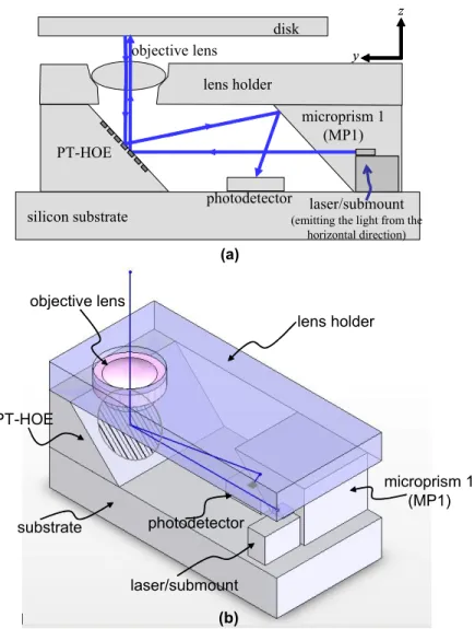
microprism 1 (MP1) PT-HOE photodetector disk laser/submount (emitting the light from the
horizontal direction) silicon substrate y z y z objective lens lens holder (a) lens holder microprism 1 (MP1) laser/submount substrate PT-HOE objective lens photodetector (b)
Fig. 2. Proposed SFF OPH design with (a) the side view and (b) the three-dimensional view of the blue-light system. 2.2 Component design
a. Objective lens design
We followed the red-light system that used the finite-conjugate relation with NA of 0.65 as the objective lens design and optimized its aspherical coefficients corresponding to the laser wavelength of 405 nm. For reducing the lens dimension and increasing the working distance, the cover layer on the recording surface of the disk was removed. For improving the molding availability, we adopted the glass material with the higher index of refraction to decrease the slopes of lens shapes on both surfaces.
b. Reflective PT-HOE design
In the proposed system, the HOE diffraction pattern is placed on the inclined surface of the MP2, which is of the prism and reflective type. It has the functions of reflecting the forward laser incident beam in the zeroth-order and diffracting the returning beam that is reflected from the disk in the first-order. In order to diffract the beam by an angle, provide the focusing servo signal, and preserve the proper intensity distribution on the photodetector, its pattern design should be included with the functions of a diffraction grating, an aberration corrector, and a cylindrical lens. Generally, we apply the binary optics technology and optimize the coefficients of the HOE phase polynomial represented by
, ) , ( 0 0
∑ ∑
= = = M m N n n m mnx y C y x φ (1)rotating each bar by 90 degrees (b) (c)
r
_-HOE
pattan coated surface/7 7 7 7 ,/ / •7 'icing line
diced bar HOEpattan coated surface I A A A A A A A A A A AIAAAAAAAAAAA
AAAAAAAAAA
AAAAAAAAAAA4
111111 I I IA L
where φ(x, y) is the phase value corresponding the point (x, y) on the HOE coordinate.
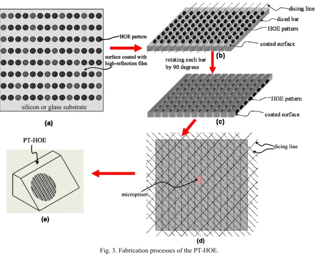
Because the HOE pattern is set on the inclined surface, it is difficult to use common fabrication methods that apply the photolithography and etching processes on substrates for fabricating planar microoptical components. We introduce a particular method that combines the standard micro fabrication with the precision mechanical dicing. Figure 3 shows the detailed steps. First, the replicated HOE patterns are etched on a silicon or glass substrate and the substrate surface is then coated with a high-reflection film. Second, the substrate with the HOE patterns is periodically and precisely diced into linear bars. Third, all bars in step 2 are rotated by 90 degrees and fixed by wax to form a plate. Finally, this plate is periodically diced again in two directions by an angle (It is 45 degrees in this design.) that will decide the inclination of the microprism. After de-waxing, the PT-HOE can be obtained.
dicing line
microprism
(d) silicon or glass substrate
surface coated with high-reflection film HOE pattern
(a)
silicon or glass substrate
surface coated with high-reflection film HOE pattern (a) (e) PT-HOE dicing line microprism (d) silicon or glass substrate
surface coated with high-reflection film HOE pattern
(a)
silicon or glass substrate
surface coated with high-reflection film HOE pattern (a) (e) PT-HOE (e) (e) PT-HOE
Fig. 3. Fabrication processes of the PT-HOE.
3. SIMULATION RESULTS
3.1 Optical system simulationWe simulated the optical performance of the proposed objective lens. The light source and image plane were placed at the conjugate points of the lens for preserving the NAs of the laser and disk sides, respectively. Figure 4(a) shows the simulated optical layout of the lens whereas Fig. 4(b) presents the ray-traced focusing spot on the recording surface of the disk. All traced rays are concentrated within the Airy disk.
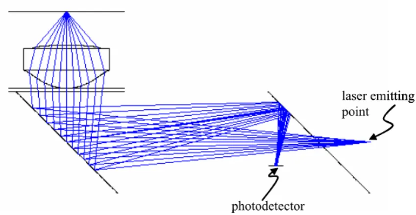
With this objective lens, the optical system of the proposed blue-light SFF OPH was built. Figure 5 shows the optical system layout. Using the system, the coefficients of first nine terms in Eq. (1) were optimized for constructing the HOE phase profile.
(a) (b)
Airy disk
Fig. 4. Simulations of the objective lens for (a) the optical layout and (b) the focusing spot.
laser emitting point photodetector laser emitting point photodetector
Fig. 5. Simulation of the optical system of the proposed blue-light SFF OPH. 3.2 Servo signal simulation
For further verifying the system’s feasibility, the servo control signal has also been simulated. Figure 6 shows the calculated focus error signal (FES) corresponding to the focus position error. In this design, the astigmatic focusing method was adopted so it would consequently result in a symmetrical S-cure as shown in Fig. 6. It gives the evidence about that the optimization of the HOE pattern is correct.
defocus distance (µm/grid)
FE S (norm ali ze d intensity)
defocus distance (µm/grid)
FE S (norm ali ze d intensity)
Fig. 6. Simulated FES (so-called S-curve).
4. CONCLUSIONS
We have presented a blue-light SFF OPH design by using a novel PT-HOE. This system has the features of a simple configuration and fewer components. Besides, we introduce a particular method for the PT-HOE fabrication. It solves the difficulty of forming the diffraction pattern on the inclined surface of a prism and provides the possibility for
implementing the proposed system. Furthermore, simulation results are satisfactory and show the feasibility for realizing the SFF OPH.
ACKNOWLEDGMENT
The authors would like to thank the National Science Council and the Ministry of Economic Affairs of Taiwan. This work was supported in part by NSC under Grant NSC 96-2221-E-005-058-MY3 and by MOEA under the Grant 95-EC-17-A-07-S1-011.
REFERENCES
1. B. W. Bell Jr., "DataPlay's mobile recording technology," Tech. Dig. Optical Data Storage 2001, 4-6, (2001). 2. D. L. Blankenbeckler, B. W. Bell, Jr., K. Ramadurai, and R. L. Mahajan, "Recent advancements in Dataplay’s
small-form-factor optical disc and drive," Jpn. J. Appl. Phys., 45(2B), 1181-1186 (2006).
3. S. M. Kang, J. E. Lee, W. C. Kim, N. C. Park, Y. P. Park, E. H. Cho, J. S. Sohn and S. D. Suh, "Development of integrated small-form-factor optical pickup with blu-ray disc specification," Jpn. J. Appl. Phys., 45(8B), 6723-6729 (2006).
4. Hsi-Fu Shih, Chi-Lone Chang, Kuei-Jen Lee and Chi-Shen Chang, "Design of Optical Head With Holographic Optical Element for Small Form Factor Drive Systems," IEEE Trans. Magn., 41(2), 1058-1060 (2005).
5. J.-S. Sohn, S.-H. Lee, M.-S. Jung, T.-S. Song, N.-C. Park and Y.-P. Park, "Design of an integrated optical pickup with NA of 0.85for small form factor optical disk drives," Microsyst. Technol., 11, 457-463 (2005).
6. K.-S. Jung, H.-M. Kim, S.-J. Lee, N.-C. Park, S.-I. Kang and Y.-P. Park, "Design of optical path of pickup for small form factor optical disk drive," Microsyst. Technol., 11, 1041-1047 (2005).
7. H. Nakata, T. Nagata and H. Tomita, "Ultra compact optical pickup with integrated optical system," Jpn. J. Appl. Phys., 45(8B), 6713-6717 (2006).
![Figure 1 shows the SFF OPH design of our previous work.[4]. That is a system with a finite-conjugate objective lens of NA 0.65 and a red laser of wavelength 654 nm](https://thumb-ap.123doks.com/thumbv2/9libinfo/7710021.146004/2.918.259.669.400.633/figure-shows-design-previous-finite-conjugate-objective-wavelength.webp)