of N 2 network nodes with merely N wavelengths. The node structure is simple since neither tunable devices nor wavelength converters are required. Packets are routed through the network by photonic fast packet switching as well as by wavelength and experience a maximum hop number of two. Multiple optical paths between any pair of nodes provide a good network survivability.
I. INTRODUCTION
HE EVOLUTION of network technology has led to
T
three generations of networks so far, distinguishable according to their underlying physical-level technology. The first one, based on copper-wire or microwave-radio technol- ogy, was developed before fiberoptic technology emerged and fully employs electronic equipments. Examples include well-known networks as Ethernet, Token Bus, Token Ring, and ARPANET. The second generation already exploits some advantages of the fiberoptic transmission technology such as the high speed of laser diodes and photonic components, or the low attenuation and dispersion of optical fibers. The partial or complete replacement of copper point-to-point links with silica fibers is characteristic for these networks and leads to better performance parameters such as higher data rates, lower error probabilities, and reduced electromagnetic sensitivity. However, changes in topology and protocol are negligible compared to networks of the first generation. Examples for second generation networks include FDDI and DQDB. Third generation or photonic networks make use of the probably most important property of optical fibers: the vast optical bandwidth. Exploitation of this bandwidth can be achieved in applying multiplex techniques with regard to wavelength (WDM), time (TDM), or waveshape (CDMA). The current favorite choice seems to be WDM because of the lower system complexity. Examples for WDM packet networks include LambdaNet [ll, ShuffleNet [2], [3], and multihop networks based on de Bruijn graphs [4]. A large number of networks of all three generations are excellently surveyed in [5].All-optical networks provide further advantages. In these networks, the information is kept permanently in the optical domain during the whole transmission from the source to the
Manuscript received February 1, 1995; revised February 12, 1996. T. Gipser is with the Swiss Federal Institute of Technology, Communication Technology Laboratory, ETH Zentrum, 8092 Zunch, Switzerland.
M . 3 . Kao is with the Department of Communication Engineering and
Center for Telecommunications Research, National Chiao Tung University, Hsinchu, Taiwan.
Publisher Item Identifier S 0733-8724(96)03877-7.
packets is avoided.
Photonic networks rely on a fiber infrastructure from which wide parts are already installed today [6]. A strong trend is going toward an increase in the number of fibers per optical fiber cable, for three reasons. First, future data traffic is expected to grow rapidly and the capacity of future optical networks will exceed that of todays networks by several orders of magnitude [7]. Second, installation cost, the main factor in the total cable cost, is not affected by the number of fibers inside a cable [8]. And third, contrary to electrical cables optical fiber cables may contain thousands of fibers [9]. It is therefore advantageous to consider the multiplicity of fibers per cable in the network design.
Network failures in high capacity networks can result in enormous loss of traffic and revenue. Desirable for the future are therefore lightwave networks with a good survivabil- ity. Mesh inetworks with their potentially high connectivity are very well suited to satisfy high survivability demands. Different mesh networks for all three network generations have therefore been proposed so far [lo]-[13]. The well- known Manhattan street network (MSN) [lo] is based on a regular mesh structure with an even number of rows and columns. A.ll nodes located in the same row or column are connected in unidirectional rings and the connection grid of all nodes forms a toroidal surface. Packets are routed by deflection and according to the consistent number of incoming and outgoing links; node buffering is not necessary. The slotted interconnected grid network (SIGnet) [ I l l is a photonic network with a piecewise-regular topology. The nodes are bidirectionally interconnected with WDM channels and packets are routed by deflection. The RookNet [12] is a regular mesh network. Each node is equipped with two transmitters for the transmission of packets to the nodes in the same row and column, respectively, and can receive packets simultaneously from all row and column nodes. In the intermediate nodes, transit packets are received, concentrated, buffered and retransmitted.
A novel photonic multihop network, called MATRIX [14], [15], is proposed in this paper. The all-optical high-speed network has a mean hop number less than two and sup- ports wavelength continuity, i.e., no wavelength translation is required in the network. Wavelength reuse as well as con- currency in wavelength and space enable the interconnection of N 2 nodes with merely N wavelengths. The node structure 0733-8724/96$05.00 0 1996 IEEE
694
Fig. 1
row zand column I ) )
Grid structure of an nzrnMATRTX (kt3 Network node located in
is simple and the nodes are equipped with integrated arrays of fixed-wavelength laser diodes and optical receivers. The lightwave network is intended to be used as a very high capacity metropolitan area network (MAN) or a wide area network (WAN).
The paper is structured as follows: The architecture of
hlA-
TRIX and the structure of its nodes are introduced in Section 11, followed by a detailed performance analysis in Section
m.
Network simulations are presented in Section IV and Section V is concerned with thconditions. A centralized carrier supply of the network nodes is discussed in Section VI1 and some concluding remarks are given in Section VIII.
Communication
Every node has there the same row and to NO direct paths exist
A node identific
11. SYSTEM DESCRIPTION
All M network nod A. Network Architecture
The network nodes, having an arbitrary geographical distri- bution and being interconnected with optical fiber cables, are virtually organized in a matrix structure as shown in Fig. 1. It is not necessary to realize every single link between two nodes with a separate cable since several links can be integrated into one optical fiber cable instead. The
in each row.
M = n . m ; n , m E { 1 , 2 , . . .},run
>
1network nodes are organized in n different rows and m different columns. In the following, all rn nodes located in
(1) row and each colu
(z + j - l)(mo
consist of In order
One fiber from both the row and column fiber cable is assigned to each node.
Fig. 3.
delay line, OB: optical buffers).
Node k22 of a 4 x 4 network (Tx: transmitter, Rx: receiver, DL:
An example is shown in Fig. 3 where the second row fiber (from the top) and the NIW Ad have been assigned to the node k22 of a 4 x 4 MATRIX. The node transmits packets to other row nodes via its row fiber and on all wavelengths except its NIW. The wavelength chosen for a packet determines the destination node in this row. The node receives all packets coming from ( m - 1) row fibers on the NIW X3.
Exactly the opposite access strategy is applied for the communication of a network node with other column nodes:
A node receives packets from the other ( n - 1) column nodes via its column fiber and on the wavelength that is identical with the NIW of the source node in this column. It transmits packets on the NIW and via the remaining column fibers assigned to other column nodes.
In the example in Fig. 3, the second column fiber (from the left) has been assigned to the node k 2 2 . The node transmits
packets on its NIW to other column nodes via appropriate column fibers. The fiber chosen for a packet determines the destination node in this column. On the other hand, the node receives packets on ( n - 1) different wavelengths from its column fiber.
The use of two different media access strategies allows a simple all-optical packet transfer from row to column channels. All packets received from other row nodes are on the same wavelength (the NIW) as are the packets transmitted to other column nodes. The processing of optical packets in a node can therefore be done on one wavelength only and without any wavelength translation. This leads to a simple and uniform structure of the network nodes.
B. Routing
Packets are routed through the network according to the wavelength and packet header information (containing the destination address). Since the average number of hops in a multihop network significantly influences both network throughput and delay, the routing algorithm has been chosen such that the average hop number in the grid topology is kept
nodekzl to nodek4~).
as small as possible. Packets in MATRIX reach the intended destination in one hop via the appropriate row (column) channels if the source node k,, is located in the same row
(column) as the destination node kk1. Otherwise, two hops are necessary and packets are transmitted first on row channels to an intermediate node k21 and then on column channels to the
desired destination node:
i = k : k2J + kzl
if
{
j = 1 : ka, k k j (5)i
#
k , j#
1 : ICa, -+ k;l -+ k k l .An example is shown in Fig. 4 where packets are transmitted from the source node kzl to the destination node k42. Packets are forwarded first on the row channel from node k21 to the intermediate node k Z 2 . This node is located in the same row as the source node kzl and the same column as the destination node k42. Then, packets are transmitted on the column channel from the intermediate node to the destination node k 4 2 .
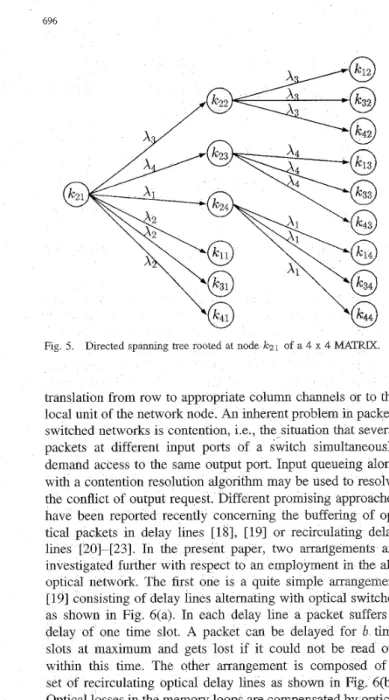
Routing in the columns of the network is accomplished by selection of appropriate fibers for transit packets. Routing in the rows of the network is done by wavelength. No wavelength translation is necessary what reveals also the spanning tree of a network node as shown in Fig. 5. The spanning tree represents a graphical representation of all paths outgoing from a specific network node and leading to all other nodes. Fig. 5 shows that each network node can be reached with one or two hops. C. Node Configuration
The configuration of a network node is depicted in Fig. 3. Each node has ( m - 1) incoming row channels. Optical filters (or frequency selective couplers) ensure that only those packets on the same wavelength as the NIW of the node are received. Incoming packets are either destined for the node or have to be switched to outgoing channels. All headers of incoming pack- ets are read with low-speed optical receivers in order to get the destination addresses [ 161. This header recognition of packets passing by is accomplished by coupling out and detecting a small fraction of the lightwave power or, alternatively, directly by a photodetection with a semiconductor laser amplifier [17]. Before they reach the optical buffers, the incoming packets are delayed for one time slot in order to enable the switch control to consider them in the next service decision.
The heart of each node is an m x n space switch. This space switch routes the incoming packets without wavelength
696
Fig 5. Directed spanning tree rooted at node IG2l of a 4 x 4 MATRIX
translation from row to appropriate column channels or to the local unit of the network node. An inherent problem in packet- switched networks is contention, i.e., the situation that several packets at different input ports of a switch simultaneously demand access to the same output port. Input queueing along with a contention resolution algorithm may be used to resolve the conflict of output request. Different promising approaches have been reported recently concerning the buffering of op- tical packets in delay lines [ 181, [ 191 or recirculating delay lines [20]-[23]. In the present paper, two arrMgements are investigated further with respect to an employment in the all- optical network. The first one is a quite simple arrangement [19] consisting of delay lines alternating with optical switches as shown in Fig. 6(a). In each delay line a packet suffers a delay of one time slot. A packet can be delayed for b time slots at maximum and gets lost if it could not be read out within this time. The other arrangement is composed of a set of recirculating optical delay lines as shown in Fig. 6(b). Optical losses in the memory loops are compensated by optical rs. The round trip time in a loop equals one time slot and a specific packet can be stored for multiple slots. New packets arriving at the memory loops get lost if all input buffers are full and if there is no possibility to forward them in the same time slot through the optical space switch. The switch control employs a simple ice discipline in order
to read out the packets from buffers. The feasibility of such buffers has been in ntensively. It has been shown that optical packets can be stored for tens of round trips in recirculating delay lines maintaining a BER well below lop9 [21] and that in principle infinite numbers of round trips are possible when optical signal regeneration is applied [25]. Furthermore, it is possible to store more than one packet in such an optical memory loop [15], [22]-[24]. However, optical loss is still high in these arrangements a
should be kept as small as possible. In and switching of optical packets is neede
that optical buffering can be avoided if time multiplexing is applied additionally.
In the local unit, whic receiver unit, newly from m transmitters network, and relayed removed from n recei The wavelengths of wavelength multiplexer to the column chan the NIW from the from the column fi array of m transmitters tion with other CO compact devices h The development of su current research on A uniform traffic calculations, i.e., a is equally likely to be de A. Average Hop Nurnbe
The connectivity gr tation of all logical lin graph indicates that to all other network be expressed as
pair of nodes, equals two. A small average hop number is important in any multihop network not only to minimize the mean propagation delay but also to maximize the number of new packets which can enter the network per time slot and, thus, the network capacity.
i,
,
pic) = m--? m follows the mean channel efficiency as
(14) n m - 1
rl(n,m) = max(n, m) . ( n
+
m - 2) ’B. Network Delay The channel efficiency for n m = max(n, m) can be calculated analOgOuslY. Hence, One has
A packet traversing MATRIX experiences an end-to-end delay
where Tprop denotes the mean propagation delay per hop, Fnode the mean waiting time in the optical buffers and Ttrans
the transmission delay (equal to one time slot). Since packets need to be buffered only once during their transmission and the average hop number
h
given in (7) is moderate, small end-to-end delays can be expected.F~~~ (15) and for n n m - l max(n,m).(n+m-2) if n m
>
max(% m ) ,= {
1 if nm = max(n, m). (15) max(n,m) - 1it can be seen that
=: m = N we get the identity
(17)
- N + 1
-
1
C. Mean Channel ESJiciency f j ( N , N ) =
-
-h ( N , N ) 2N ’
The channel efficiency, a measure of how efficiently chan- nels are used in a network, depends on the average hop number and the traffic load in the network.
Each node has ( m - 1) incoming row channels (on the wavelengths). Similarly, ( n - 1) column channels and ( m - 1) row channels are originating from each node. The connectivity degree c, defined as the number of channels leading to or originating from a node [30] equals, therefore,
(10)
with the
NIW) and ( n - 1) incoming column channels (on different
P
51
(18)indicating the ratio between the number of rows and columns in the network, the channel efficiency f j in (15) can be expressed as
c = n + m - 2.
M-l if n m
>
max(n, m ) , if n m = max(n, m ) (19) The total number of channels in the network is thenwT = C . M . (1 1)
The mean channel efficiency r] in a multihop network can be expressed as
where S(”) denotes the normalized successful load on channel w and p p ) the probability that a packet on channel w needs h hops to reach its destination.
In MATRIX, the normalized successful loads on all row channels (index R ) are identical and so are the loads on the
and becomes for large M
(20) if nm
>
max(n,m), if ~m = max(n’ m). M-CCThe mean channel efficiency f j as a function of M for different values of /3 is shown in Fig. 7. Note, that a high channel efficiency is achievable in the network which reaches the maximum for /3 = 1.0 with a given M . The limit of the channel efficiency given in (20) is also plotted for different values of
p.
698
M Fig 7
different values of fl D. Network Capacity
Channel capacity in multihop networks has to be shared between newly generated traffic and relayed traffic. The max- imum new traffic generated by all nodes which may be transmitted through the network defines the network capacity. In general, the network capacity C of a multihop network can be expressed as the sum of all link capacities C("), i.e.,
Mean channel efficiency vas a functlon of the number of nodes Mfor
For equal hop-probabilities p p ) = p h on every channel w, (21) changes to
h m a x W T
c
=E?
h (22)h = l w = l With'
the network capacity follows as
(24) 1
h
wTc
= YS(").
w = lA small average hop number
5
is therefore crucial in order to achieve a high network capacity. From (12) and (21) one hasC =
7 .
W T . (25)The network capacity of MATRIX under uniform traffic con- ditions can be expressed with (15), (ll), (lo),
min(n, m )
.
(nm - I ) max(n, m)From (26) the expression
if nm > max(n, m ) , if nm = max(n, m ) . (26)
C ( n , m ) = C(m,n) (27)
C ( n , m ) =
'
Note, that p h is not the probabihty of a h-hop packet leaving the network, therefore 2 # h p h holds, i.e., an n x m m x n. network. The combination o ity as a function ofi
C ( P l M ) =Since each node has acces node equals
and with (15) and (
function of M The maximum d
where R c represents channels. The high c
at a data rate of rate of 10 Mb/s fo
IV. NETWORK SIMULATIONS The analytical resu
been compared with been implemented as a s
m = 4 in the sim generated in the
60- 40- 20 . . . .:. ... :_. . . ..I.;.. -. ...
-
... : ... i ... i ... ..: _ . ... ..:. ... i ... .; ... I -. ... I 10 20 30 40 50 b 0.6#Fig. 9. Throughput performance T,, of an NzNspace switch with optical input buffering as a function of the number of buffers b for different switch sizes N (- arrangement with recirculating delay lines, - - arrangement with delay lines). ?“de 100 80
t
I I1
.. b.;..N..=...+ ... i ... i ...:I../.
PFig. 10. Mean waiting time (in slots) in the optical buffer arrange- ments as a function of the load p for different switch sizes N (- arrangement with recirculating delay lines, - - arrangement with delay lines).
and are transmitted simultaneously on the network links. Furthermore, the mean propagation delay per hop Tprop in the network is equal to one time slot. A simple and therefore fast service discipline (described in [31, p. 15881) was applied for service decisions in the network nodes.
Figs. 9 and 10 show the throughput T,, and the mean waiting time ?=no& of an N x N space switch with optical input buffers consisting of delay lines and recirculating delay lines as given in Fig. 6. Note, that despite the different physical configurations the performance of both buffering arrangements
is very similar. The slightly higher throughput of the buffering arrangement with optical delay lines compared to that one with recirculating delay lines is due to the fact that packet losses in the first arrangement occur at the end of the buffering stage. Since the contention resolution algorithm considers the packets at the end of the buffering stage first, “problem” packets are automatically chosen with higher priority in the service decisions. However, the arrangement with recirculating delay lines shows a higher flexibility compared to the arrangement with optical delay lines.
Optical input buffering with recirculating delay lines was chosen for the simulations of a 4 x 4 network. Fig. 11 shows the aggregate network throughput for different numbers of
P Fig. 11. Aggregate network throughput T as a function of the load p for
different buffer sizes b.
P
Fig. 12.
function of the load p for dlfferent buffer sizes b.
Aggregate network throughput T in the network with ACK as a
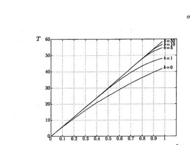
optical buffers b per input queue. The maximum achievable throughput T coincides with the network capacity analytically derived in (26). The results shown in Figs. 12 and 13 are obtained whien packet acknowledgment (ACK) is taken into consideration. It can be seen that the throughput equals the maximum achievable throughput with increasing p as long as the links are not saturated due to retransmitted packets. The more buffers are used the lower is the probability that a packet has to be retransmitted. Note, that the delay increases significantly when the network links get saturated.
V. NETWORK SURVIVABILITY
Survivability is a key concern in networking and will become increasingly important in future optical networks as they carry a steadily growing traffic. Any failures in high capacity networks could result in an enormous loss of traffic and revenue [32]. In case of a link or node failure the network
has to retain its connectivity, i.e., as few nodes as possible should be affected by the failure. According to their topology mesh networks are well suited to satisfy high reliability demands.
The simplest way to overcome a node or link failure is to force any node in case of a failure to send packets first to those network nodes, whose links to the destination node
700
P
Fig 13 End-to-end delay D (in slots) in a network with ACK as a function
of the load p for different buffer sizes b(a: b = 0,b: b = 1,c: b = 5,d:
b = 10, e b = 50
are not affected by the failure. These additional intermediate nodes receive the packets and retransmit them like newly generated packets to the destination nodes. However, this failure treatment implies a detour via the electrical domain. In contrast, a slight enhancement of the node structure provides all-optical paths even in the case of a network failure.
MATRIX is composed of different subnets consisting of space switches as well as the channels leading to each switch from other row nodes and those leading from the switch to other column nodes. Each of these subnets works on a specific NIW and forward only traffic on this wavelength. Different subnets are independent and have no links between them.
In
the whole network exactly
- = min(n,m) (32)
M N
space switches work on a given wavelength
Al. A small
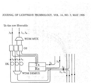
enhancement of the nodes enables the interconnection of the min(n,m) space switches working on the same wavelength and, therefore, many additional all-optical paths in the net- work.According to Fig. 3, a node receives packets exactly on the same wavelengths from the column nodes as it uses for its communications with other row nodes. This property is exploited in the enhanced node structure as shown in Fig. 14. The enhancement enables the nodes to route packets not only from row to column channels but also from column to row channels. All incoming packets from column channels are received as discussed in Section 11, but some of them might now be destined for another node. In that cas
the transit packet in the appropriate delay line is forwarded to the row fiber in the next time slot. New packets generated at the node and requiring simultaneous access to the same row fiber channel are retained and transmitted in the next free time slot. This backpressure mechanism automatically throttles sources as network failures occur and fits continuously the number of packets offered to the optical network to the available transmission capacity. Note, that the modification of the node is very simple since neither additional receivers (for the packet header recognition) wavelength converters nor additional optical buffers are required.
To the row fibercable
DL
Fig. 14. Enhanced netwo
Many additional opti with enhanced network the whole set A for their c units (transmitter units) dispose
A’
C
A, the following relationbetween node k13 and from source node kl
rvsed in order to send p It is therefore possibl VI. NETWORKBE The calculations in uniform traffic is nonuniform fic patterns, s can not be de However, an uppe be expressed. The pattern in the network is
where the first term capacity of a networ
of its transmitters or rec e the number of nodes in
Fig. 15. Survivability routing in the optical domain in a 4 x 4 MATRIX (Example: Failure between the source node ]clsand the destination IC43 and detour via nodes k14 and k 2 4 ) .
traffic pattern has the property that any node has a slightly higher traffic with the row and column nodes than with the remaining nodes of the network. Note, that C,,, is only insignificantly higher than the network capacity C(n, m )
in (26) under uniform traffic conditions. For more realistic nonuniform traffic patterns it has been shown that in multihop networks the throughput per node is reduced by a factor of about 0.3 to 0.5 compared to the values predicted for the uniform traffic case [34].
MATRIX is highly flexible if certain network nodes need additional transmission capacity. The average transmission capacity available for unidirectional traffic between two nodes and for uniformly distributed traffic is with (30) for nm
>
max(n, m )(34) The transmission capacity C,, between two network nodes can be increased significantly. As stated in the previous section, min(n, m ) optical paths are always available between any pair of network nodes. If a transmitter of the source node transmits packets only to one destination node, a capacity C,, = 1 is available between the two nodes. If all available optical paths are used simultaneously and provided that the traffic demand of the other network nodes is low enough, a maximum transmission capacity
results. Therefore, in case of increased traffic demands the transmission capacity available for unidirectional traffic be- tween individual network nodes can be varied in a wide range. Note, that this additional transmission capacity is provided without wavelength translation or detour over the electrical domain.
VII. CENTRALIZED CARRIER SUPPLY
As discussed in Section 111, c channels are originating from each network node. Each node disposes of m transmitters working on different wavelengths from the set A in order to offer newly generated packets to the network. These trans- mitters can be realized with narrow-linewidth semiconductor lasers being well-suited for long-haul transmission. In this case each node has to provide local control for the laser transmitters in order to guarantee wavelength stability. However, since
A is the same for all network nodes, a centralized carrier supply can be used instead of generating the carriers separately at each node. A set A of N stable wavelengths exhibiting narrow linewidths and little wavelength drifts is delivered from a common wavelength generation center (WGC) to all network nodes on a carrier distribution fiber via the row and column fiber cables. At each node, a multiwavelength transmitter unit is used to implement the m transmitters as shown in Fig. 16. The device consists of an optical amplifier at the input, followed by a WDM demultiplexer to separate the
N wavelengths. The required m wavelengths are modulated
by m external modulators.
The centralized carrier supply provides several advantages. First, merely one set A of stable and narrow linewidth carriers has to be generated at the WGC instead of generating the carriers at each node individually. Hence, the carrier set used in each node is identical, and therefore no wavelength ambiguity appears among the network nodes. Second, the narrow linewidth carriers together with an external modulation represent an excellent solution for dispersion-limited long-haul transmissions. In addition, the multiwavelength transmitter unit can be monolithically integrated in order to be a reliable and simple device. On the other hand, the centralized carrier supply has to fulfill hard requirements with regard to reliability and survivability of the network. However, it is possible to operate a spare WGC in case of a failure.
VIII. CONCLUSION
MATRIX is a network in which the number of wavelengths, the number of fibers, and the average number of hops are
well balanced. As a main property, the all-optical network supports an information exchange with wavelength continuity. Packets are routed according to their wavelengths and with space-division switching. Provided that no network failures occur, buffering and switching of optical packets are needed merely once between source and destination node. This is
702
advantageous since buffering and switching still involve high optical losses. In case of network failures, packets can be routed on alternative all-optical paths through the network. The node structure is uniform and simple in the sense that each node has to process only packets on one wavelength. Finally, it has been shown that a certain regularity of the network architecture may imply significant simplifications in the node structure.
ACKNOWLEDGMENT
The authors would like to extend their appreciation to P. Leuthold, Director of the Communication Technology Labo- ratory, ETH Zurich, for the support of this research.
REFERENCES
[ l ] M S Goodman, H Kobnnsh, M P Vecchl, R. M. Bulley, and J L. Gimlett, “The LambdaNet multiwavelength network fu-chitf+xe, aDolications and demonstration,” IEEE J SeZect Areas Commun., vol 8: p p . 995-1004, Aug. 1990.
121 A S. Acamuora, “A multichannel multihop local lightwave network,” in Proc GLbBECOM’S7, Nov 1987, vol. 3, pp 1459-1467.
[3] M G Hluchyj and M J Karol, “ShuffleNet An apphcahon of gener- alized perfect shuffles to mulhhop lightwave networks,” J. Lzghtwave Technol, vol 9, pp 1386-1397, Oct 1991
[4] K Sivarajan and R Ramaswarm, “Lightwave networks based on de Bruijn graphs,” IEEE/ACM Trans Networkzng, vol 2, pp 7G79, Feb
1994
[5] H R van As, “Media access techniques The evolution toward ter- abius LAN’s and MAN’S,” Comput Networks ISDN Syst , vol 26, pp. 603-656, Mar 1994
161 D W Smth, “The road to superhghways,” in Proc. ECOC’94, Sept. 1994, vol 2, pp 903-906
[7] P E, Green, “The future of fiber optic computer networks,” IEEE
Cornput, vol 24, pp 78-87, Sept 1991
[SI J Bannister, M Gerla, and M. KovaceviC, “An all-ophcal mulhfiber tree
network,” J Lzghtwave TechnoZ , vol 11, pp. 997-1008, MayIJune 1993.
[9] K Hogan, K Nakayama, and F Ashiya, “Design and performance of 2000-fiber cable,” J Opt Commun , vol 14, pp 202-207, Dec 1993. [lo] N F Maxemchuk, “Routing in the Manhattan street network,” IEEE
Trans Commun , vol 35, pp 503-512, May 1987
[ l l ] T D Todd and A M Bignell, “Traffic processing algonthms for the SIGnet metropolitan area network.” IEEE Trans Commun., vol. 40, PP
_ _
568-576, M&. 1992
r121 Y Ole, Y. Sasaki, and H Mivahara, “RookNet: A switching network for high speed communicatl&,” in Proc ICC’93, May 11993, pp.
1225-1230
[13] H A Jager, “WDM-Gridconnect as a transpoa structure,” IEEEPhoton.
Technol Lett, vol 7 , pp 576-578, May 1995
[14] T Gipser and M S Kao, ‘‘MATRIX A new network for multi- wavelength all-optical transparent informahon exchange,” m Pruc. EFOC&N’94, June 1994, pp 146-150
1151 T Gipser and M S Kao, “MATRIX An all-optlcal hgh-speed network architecture,” in Proc ECOC’94, Sept 1994, vol. 1, pp. 499-502
[16] Z Haas and R D Gitlin, “Field coding A hgh-speed ‘almost-all’ ootlcal interconnect.” in Proc 25th Annu Conf Inform Sci. Svst.. Mar “~
1591, pp 834-839
[17] H Nakajima, “High-speed and hgh-gam optical amplifying photode- tectlon in a semconductor laser amplifier,” Appl. Phys Lett., vol 54,
pp 984-986, Mar 1989
[18] 2 Haas, “The staggering switch An electromcally controlled packet switch,” .7 Lightwave Techno2 , vol 11, pp 925-936, May/June 1993
[19] I Chlamtac and A Fumagalli, “An optical switch archtecture for Manhattan networks,” IEEE J Select Areas Commun, vol 11, pp
~-
550-559, May 1993
[20] J Spring and R. S. Tucker, “Photonic 2 x 2 packet switch with input buffers,” Electron Lett., vol 29, pp 284-285: Feb 1993
[21] W. Pieper, M Eiselt, G Grosskopf, R Langenhorst, A Ehrhardt, and H G Weber, “Investlgation of crosstalk interference in a fiber loop opt~cal buffer,” Electron Lett, vol. 30, pp 435436, Mar. 1994.
[22] M Calzavara, P Gambini, M. Puleo, B Bostica, P Cinato, and E. Vezzoni, “Simultaneous buffenng of ATM packets in a muluwavelength optical fiber-loop memory,” in Proc OFC’94, Feb. 1994, pp 195-96.
JOURNAL OF LIGHTWAVE TECH Y. Yamada, K. Sasay
frequency-division-mu1 Gbitk,” Electron Lett
T. G. Hodgkinson and
S. Gozdz, N. C Andr
M. Decina, V Trecorm,
king,” IEEE J. Select Areas Commun , vo
candidate at the Communicahon Technology Labo- in Zurich.
tion Technology Laboratory where he designed
architectures.
where he i s now a Profess Between 1993-1994, he was of Technology (ETH), Zur of optical communications. networks and CATV net
![Fig. 15. Survivability routing in the optical domain in a 4 x 4 MATRIX (Example: Failure between the source node ]clsand the destination IC43 and detour via nodes k14 and k 2 4 )](https://thumb-ap.123doks.com/thumbv2/9libinfo/7500136.116280/9.928.433.834.59.278/survivability-routing-optical-matrix-example-failure-source-destination.webp)
