2142 IEEE JOURNAL ON SELECTED AREAS IN COMMUNICATIONS, VOL. 19, NO. 11, NOVEMBER 2001
A Programmable Pipelined Digital Differential
Matched Filter for DSSS Receiver
Ching-Hung Chiou, Chao-Wang Huang, Kuei-Ann Wen, and Mau-Lin Wu
Abstract—A programmable pipelined digital differential
matched filter (PDMF) implemented for a direct sequence spread spectrum receiver is proposed in this paper. To reduce the power consumption, the architecture PDMF is based on the synchro-nization combined PN code phase acquisition algorithm (Huang
et al., 1999). Compared with the conventional PN code phase
acquisition algorithm, the theoretical analysis result indicates that the PDMF acquires both power efficient and preferable detection. Depending on different applications, programmability allows the PDMF to implement 3-tap, 5-tap, or 11-tap Barker codes with the same hardware but different precisions for each tap coefficient. For short tap Baker codes, the architecture could adopt more precision on each tap coefficient to resist the channel noise. Simulation results also show that there are fewer errors of high sample precision with the same tape.
Index Terms—Baker code, DSSS, low power.
I. INTRODUCTION
D
IRECT sequence spread spectrum communication systems have been attached so much importance for possessing relatively more desirable features than the other communication schemes. Some of those fascinating attractions are multipath rejection, antijamming capability, low probability of interception, and so on [1]–[3]. However, in spread spectrum system design, the initial synchronization of the spreading waveforms is very significant. The uncertainty in the estimated propagation delay contributes to a large number of symbols of code phase uncertainty, while the Doppler effect and the instability of the oscillator result in frequency uncertainty also have to be resolved. Among many PN code phase acquisition algorithms, the matched filter is regarded to be a very efficient measure to acquire the initial synchronization [4]. However, when the number of stages of a conventional digital matched filter (CDMF) increases, the amount of multiplications and accumulations will be greatly increased. In order to improve on such a major shortcoming of the CDMF, a modified structure, differential digital matched filter (DDMF), was proposed to reduce the complexity of spread spectrum correlators [5]–[7]. The numerical complexity of DDMF, measured as accumulate and multiply operations, was found to approach half of that of the CDMF.In this paper, a programmable-pipelined digital differential matched filter (PDMF) based on the synchronization combined PN code phase acquisition algorithm (SCA) [9] is proposed
Manuscript received May 2, 2000; revised January 1, 2001.
The authors are with the Institute of Electronics, National Chiao-Tung University, Hsin-Chu, 300, Taiwan R.O.C. (e-mail: karl.ee89g@nctu.edu.tw; cwhuang.ee87g@nctu.edu.tw; kawen@cc.nctu.edu.tw; mlwu.ee87g@nctu. edu.tw).
Publisher Item Identifier S 0733-8716(01)09080-1.
TABLE I VALUES OFmANDt
and presented. This newly developed programmable architec-ture can be programmed, from 12-bit precision for 3-tap Baker codes down to 4-bit precision for 11-tap Barker codes, which depends on the applications. And, using the SCA algorithm en-ables the PDMF to perform a better power efficiency than that of the CDMF. The programmable architecture of the PDMF is described in detail in Section II, and the numerical results of the PDMF are given in Section III in comparison with those of a CDMF. The comparisons between PDMF, CDMF, DDMF [6], and low complexity correlator [7] are shown and discussed in Section IV.
II. SCA ALGORITHM
The algorithm adopted for the programmable PDMF is the SCA [9]. Compared with the conventional PN code phase ac-quisition algorithm, SCA has a higher detection probability and a lower false alarm rate. Following is a brief description of the SCA algorithm.
1) Assume that there exists a set of partitioned into two
states of nature, and , with and
. One of these two states prevails as the observations are made, and that prevailing state is un-known to observers.
2) Assume that the channel is an additive white Gaussian noise (AWGN) channel with the probability density func-tion (pdf) of . Consequently, the pdf of the re-ceived signal is either
or .
3) As the source data is and it is spread into
-tu-ples , then a real vector
data
, which is probabilistic in nature and represents a manifestation of the state of nature, can be obtained.
4) The cross-correlation function of the PN code phase
syn-chronizer is depicted as .
5) If the phase of the PN code were synchronized, the conditional pdf of the autocorrelation function becomes 0733–8716/01$10.00 © 2001 IEEE
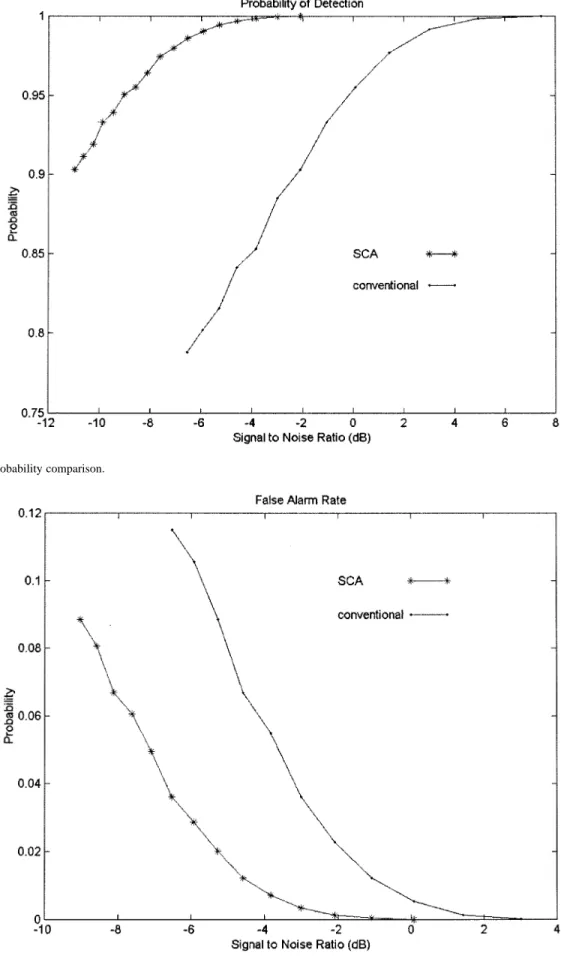
Fig. 1. Detection probability comparison.
Fig. 2. False alarm rate comparison.
given or given . If not
synchronized, the pdf of the autocorrelation function of
the PN code phase synchronizer becomes or .
2144 IEEE JOURNAL ON SELECTED AREAS IN COMMUNICATIONS, VOL. 19, NO. 11, NOVEMBER 2001
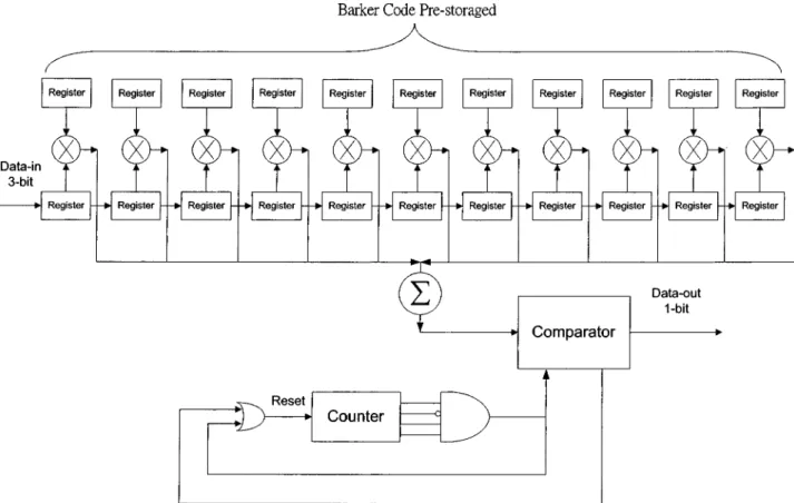
Fig. 3. The architecture of the SCA for 11-tap Barker codes with a 3-bit A/D.
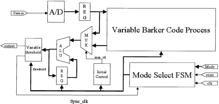
Fig. 5. Block diagram of the architecture of PDMF.
6) Assume that the decision function of the PN code phase synchronizer is , whose domain is the set of all real valued -tuples and range is .
7) Define and is
the joint probability that the state of nature is . Based on and the function , the estimated or perceived state of nature is . If , the decision is correct; if , then an error happens and a penalty (cost) is incurred [10]. A. Detection Probability Analysis
Assume that , as analyzed in [9]; if the PN
code phase were synchronized, the detection probability for PN code phase acquisition algorithm with -tuples and a threshold
is given as
(1)
B. False Alarm Rate Analysis
If the PN code phase were not synchronized, the false alarm rate for rapid PN code phase acquisition algorithm with -tu-ples and a threshold would be
(2)
TABLE II BARKERCODES
TABLE III COEFFICIENTS OF THEPDMF
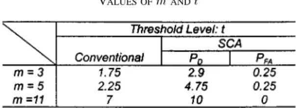
The values of code-length and threshold level are given in Table I.
The detection probability and false alarm rate of SCA for 11-tap Barker codes
, for example, are given as follows:
2146 IEEE JOURNAL ON SELECTED AREAS IN COMMUNICATIONS, VOL. 19, NO. 11, NOVEMBER 2001
Fig. 6. Block diagram and behavior of A/D converter.
(4) Figs. 1 and 2 illustrate the detection probability and false alarm rate of SCA with 11-tap Barker codes compared with the con-ventional algorithm.
The architecture of SCA for 11-tap Barker codes with a 3-bit A/D converter [9] is illustrated in Fig. 3. The incoming signal was sampled and quantized into eight levels, (4, 3, 2, 1, 1, 2, 3, 4), convenient for code phase acquisition and storage in the 11 shift registers. Thus, after being multiplied with the prestorage PN code and cumulated, the cross-correlation value of the incoming signal and PN code will be between 44 and 44. The threshold level was set to 24 or 24 for a conventional PN code phase acquisition algorithm and 36 or 36 for the SCA. If the clock of the SCA counts to 11 and the cross-corre-lation value is between 36 and 36, the clock will be reset and the threshold level will be adjusted to 0.
The power efficiency of the SCA and the conventional algo-rithm is illustrated in Fig. 4. In this figure, it can be observed that the bit–error rate (BER) decreases as a result of the length of the Barker code increase. The application of the SCA algo-rithm can improve the power efficiency of the conventional al-gorithm and the range of improvement differs with the length of the Barker code. For example, the SCA can reform the BER of 3-tap and 5-tap Barker codes in an order of two. However, for 11-tap Barker codes, the SCA performs 4 5 dB better than the conventional algorithm.
III. ARCHITECTURE OFPDMF
According to the CDMF, the result of the direct-form finite impulse filter (FIR) configuration could be expressed as follows:
(5)
(6) The indicates the length of the PN code, is the PN code co-efficient, and is the received signal. To reduce the number of multiplications and summations, a differential PN code scheme was proposed in [6]. The expression of the pipeline digital dif-ferential match filter can be described as follows:
where are either or
are either or
except and (7)
For the coefficient 0, there is no demand for multiplication. Therefore, the switching activity of the multiplier could be min-imized, and the dynamic power dissipation of the multiplier would also be reduced.
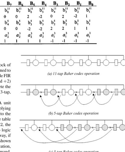
In order to figure out the synchronized problem and to min-imize the power consumption, a new architecture PDMF using the SCA algorithm was proposed. Besides using a differential PN code coefficient number to minimize the switch activity of those multipliers, the architecture also applies the strategy to share the same hardware for processing different PN codes. In Table II, the well-known Barker code with 3-, 5-, and 11-taps is listed. After differential processing, the entire coefficients for the PDMF were acquired and have been listed in Tables II and III.
A. Block Diagram of PDMF
According the measure described in the previous paragraphs, the complete function block of the proposed PDMF architecture has been developed and illustrated in Fig. 5, which processes differential 3-tap, 5-tap, and 11-tap Barker codes in the same equipment. The system architecture of the present architecture consists of an A/D unit, a variable barker code processor, a vari-able threshold unit, an initial control unit, a mode select FSM unit, and some random logic units. In order to provide a better illustration of the mechanism, the whole block was decomposed into many subblocks and a more detailed operation is presented in the figures.
Fig. 6 shows block diagram and the behavior of an A/D con-verter. In the application of 3-tap Baker codes, the incoming signal would be sampled and quantized into 16 bits. In that case, the register latches the result and passes it to the FIR filter for further processing. However, for 5-tap Baker codes, the A/D converter will quantize the signal into 8 bits and allocate it into Bus BA and Bus DC. With the same method, Bus DCBA car-ries the same 4-bit quantized signal for 11-tap Baker codes pro-cessing. Basically speaking, the “initial control” block is used to look up the initial value from the item from (5). When the incoming data is fed into the input port, the control signal mux_ctl will go low to start up the input data accumu-lation. The control signal mul_ctl will go high right after the value of reached the Baker code tap length, and the data input will go on but be fed from the Variable Baker Codes
Fig. 7. Circuit design of Variable Barker Code process.
Fig. 8. Circuit design and state table for M&C unit of 0, 1,01, 02, 2. Process block instead of directly from the register. The Mode Select FSM unit based on the SCA algorithm is to generate the proper threshold value for the Variable Threshold unit. With the
application of this mechanism, it will reduce the synchroniza-tion time of the correlator and also lessen the power consump-tion.
2148 IEEE JOURNAL ON SELECTED AREAS IN COMMUNICATIONS, VOL. 19, NO. 11, NOVEMBER 2001
TABLE IV
COEFFICIENTB ; B ; B ; B 1 1 1 B FOREACHM&C UNIT
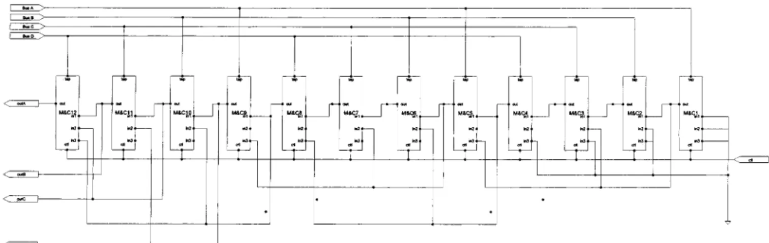
B. Variable Barker Code Process Block
The variable barker code process block is the major block of the PDMF architecture shown in Fig. 7. The block is designed to despread the incoming sequences based on a programmable FIR filter equation with binary coefficient (0, 1, 1, 2, and 2) along with the 12-M&A (multiplier and adder) to complete the functionality. Manipulated by proper control signals, the 3-tap, 5-tap, or 11-tap correlation results can be well obtained.
In order to lessen the hardware, a specialized M&A unit must be developed to feature in taking advantage of multiplying simple coefficient and adding selected input. According to the type of Baker codes, the control activities follow the state table shown in Fig. 8. If the multiplication coefficient , the in_ctl and m_ctl are all set to logic 1 and as_ctl is set to logic 0. Otherwise, as_ctl is set to 0 for . In the same way, if , 1 or 0 could be implemented as the state table shown in Fig. 8. In addition to the coefficient control of multiplication, the sel signals manipulate the selection of the adder’s summand. All of the observations infer that a binary ripple adder appears to be the better choice for hardware minimization.
Twelve sets of basic M&C elements are applied to construct the variable Baker code processor. The previous stage M&C’s co port was connected to the next stage M&C’s cin port, and the Variable Barker Code Process block is constructed with a similar connection. For processing different coefficient taps, Table IV covers the reference values of coefficient
for each M&C unit.
The operation of the M&C unit is illustrated in the diagrams in Fig. 9. As shown in Fig. 9(a), if the tap of the Barker codes is 11, the register of all M&C units could not be bypassed and the sel signals of all M&C units are set to logic 0. Thus, the total latency of the Variable Barker Code Processing is a 12-clock cycle. Fig. 9(b) shows another case for 5-tap Baker codes. In order to be the summand of the M&C3s, the M&C1’s output must be connected to the multiplexer’s input of the M&C3. Sim-ilarly, the output of M&C2 is connected to M&C4’s multiplexer. Therefore, all of the signals at the control pin cin_ctl of the M&C unit are set to (0, 1, 0, 1, 0, 1, 0, 1, 0, 1, 0, 1), then the total la-tency of the Variable Barker Code Processing is derived to be a 6-clock cycle. Fig. 9(c) shows the connecting method for 3-tap Baker codes. And, the total latency will reduce to 3-clock cycle with cin_ctl set to (0, 1, 1, 1, 0, 1, 1, 1, 0, 1, 1, 1).
By the same method, some different spreading signals for dif-ferent protocols such as 802.11, IS-95 could be combined into the same match filter to share the hardware. For more analysis,
Fig. 9. Different Baker code operation example.
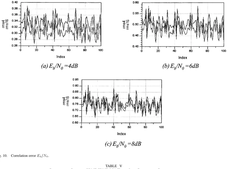
the affect of the sampling precision has been performed. Fig. 10 displays the simulation results of 3-tap Baker codes root mean square (rms) errors between source data and received data (4 and 16 precision bits) on different . From the observation, a higher precision will reduce the error of received data from the simulation results. If the coefficient taps are 3, 16-bit precision would be good enough to resist noise disturbance. More coeffi-cient tap is required to deal with high noise disturbance in the environment since variable spreading code takes advantage to get better channel efficiency and to resist noise.
IV. COMPARISON
In comparison with CDMF, DDMF [6], and low complexity correlator [7], the architecture of the PDMF has those features. First, the PDMF can reduce propagation delay of the summa-tion compared with the CDMF. Second, the funcsumma-tion of the PDMF could be reconfigured to change the precision bit width of the samples it can handle, from 16-bit precision for 3-tap Barker code, down to a 4-bit precision 11-tap Barker code. Although PDMFs have more propagation time compared with DDMF by 3-tap Baker codes, they will have the advantage of high precision to resist channel noise. These features make the PDMF more suitable for variable tap coefficient direct
Fig. 10. Correlation errorE =N .
TABLE V
COMPARISONSBETWEENPDMF CDMF, DDMF,ANDLOW-COMPLEXITYCORRELATORS
sequence spread spectrum (DSSS) communication systems. The comparisons between PDMF, CDMF, DDMF, and low complexity correlators are summarized in Table V.
V. CONCLUSION
A new architecture-PDMF-adopted SCA algorithm is pro-posed. The theoretical analysis indicates that the PDMF ac-quires both power efficient and preferable detection. In partic-ular, the PDMF could operate different PN codes in the same hardware with different precision bits depending on the appli-cations.
REFERENCES
[1] M. K. Simon, J. K. Omura, R. A. Scholtz, and B. K. Levitt, Spread
Spec-trum Communications: Maryland Computer Science Press, 1985, vol.
I-III.
[2] R. L. Peterson, R. E. Ziemer, and D. E. Borth, Introduction to
Spread-Spectrum Communications. Englewood Cliffs, NJ: Prentice Hall, 1995.
[3] A. J. Viterbi, CDMA Principles of Spread Spectrum
Communica-tion. New York: Addison-Wesley, 1995.
[4] Y. T. Su, “Rapid code acquisition algorithms employing matched filter,”
IEEE Trans. Commun., vol. COM-36, June 1988.
[5] G. J. R. Povey and P. M. Grant, “Simplified matched filter receiver design for spread spectrum communication applications,” Electron.
2150 IEEE JOURNAL ON SELECTED AREAS IN COMMUNICATIONS, VOL. 19, NO. 11, NOVEMBER 2001
[6] W. C. Lin, K. C. Liu, and C. K. Wang, “Differential matched filter ar-chitecture for spread spectrum communication systems,” Electron. Lett., vol. 32, no. 17, pp. 1539–1540, 1996.
[7] B. S. E. Tan and G. J. R. Povey, “Low complexity spread spectrum cor-relator,” Electron. Lett., vol. 33, no. 14, pp. 1204–1205, 1997. [8] D. Garrett and M. Stan, “Power reduction techniques for a spread
spec-trum based correlation,” in Proc. Int. Symp. Low Power Electronics and
Design, 1997.
[9] C.-W. Huang, K.-A. Wen, and M.-L. Wu, “Synchronization combined PN code phase acquisition algorithm (SCA) for DSSS receiver,” in IEEE
42nd MWSCAS Conf., 1999.
[10] H. Stark and J. W. Woods, Probability, Random Process, and
Esti-mation Theory for Engineers. Englewood Cliffs, NJ: Prentice-Hall, 1994.
[11] D. Wiggert, Codes for Error Control and Synchronization. New York: Artech, 1988.
Ching-Hung Chiou received the B.S. degree from Fu Jen Catholic University and the M.E.E. degree from the Department and Institute of Electrical En-gineering, National Chiao-Tung University, Taipei, Taiwan, R.O.C. in 1990 and 1998, respectively. Since 2000, he has been pursuing the Ph.D. degree at the same university.
He was a Radar System Designer at Chung Shan Institute of Science & Technology, Tao-Yuan, Taiwan, R.O.C., from 1992 to 2000.
Chao-Wang Huang received the B.S. and M.S. de-grees from the Department of Electrical Engineering and Institute of Electronics, National Chiao-Tung University, Hsinchu, Taiwan, R.O.C., in 1996 and 1998, respectively and is currently a Ph.D. student in the Institute.
Kuei-Ann Wen received the B.E.E., M.E.E., and Ph.D. degrees from the Department of Electrical Engineering and Institute of Electrical and Computer Engineering, National Cheng Kung University, Tainan, Taiwan, R.O.C., in 1983, 1985, and 1988, respectively.
She is presently a Professor in the Department of Electrical Engineering, National Chiao Tung Univer-sity, Hsinchu, Taiwan, R.O.C.
Mau-Lin Wu received the B.E.E. and M.E.E. de-grees from the Department and Institute of Electrical Engineering, National Taiwan University, Taipei, Taiwan, R.O.C., in 1994 and 1996, respectively. He is currently pursuing the Ph.D. degree at National Chiao Tung University.
He was a VLSI Circuit Designer at Taiwan Semiconductor Manufacturing Company, Hsin-Chu, Taiwan, R.O.C. from 1996 to 2000. Since 2000, he has been an IC Designer at Integrated Circuit Solution Inc., Hsin-Chu, Taiwan, R.O.C., where he is focused on design of wireless communication systems.