國
立
交
通
大
學
網路工程研究所
碩
士
論
文
同儕網路電視中透過預取和頻道偵測以改
進轉台與播放效能之研究
A Study of Improving Channel Switch and Playback
Efficiency in P2P IPTV based on Pre-fetching and
Channel Monitoring
研 究 生:李書賢
指導教授:陳耀宗 教授
同儕網路電視中透過預取和頻道偵測以改進轉台與播放效能之研究
A Study of Improving Channel Switch and Playback Efficiency in P2P
IPTV based on Pre-fetching and Channel Monitoring
研 究 生:李書賢 Student:Shu-Hsien Li
指導教授:陳耀宗 Advisor:Yaw-Chung Chen
國 立 交 通 大 學
網 路 工 程 研 究 所
碩 士 論 文
A ThesisSubmitted to Institute of Network Engineering College of Computer Science
National Chiao Tung University in partial Fulfillment of the Requirements
for the Degree of Master
in
Computer Science
July 2012
Hsinchu, Taiwan, Republic of China
同儕網路電視中透過預取和頻道偵測以改進轉台與播放效能之研究
學生:李書賢
指導教授:陳耀宗 博士
國立交通大學網路工程研究所
摘要
光纖到戶日漸普及使得網路頻寬增大,進而促成即時影音串流之應用,因此現今 在網路上可以看到許許多多的電影與電視連續劇,都有不錯之品質。未來數位電視將 趨 向 透 過 網 際 網 路 來 傳 送 影 音 媒 體 資 料 , 這 可 歸 功 於 過 去 十 年 來 點 對 點 (Peer-to-Peer;P2P),或同儕網路技術的發展。透過 P2P 技術提供媒體串流服務,可以 節省大筆伺服器軟硬體成本,同時其良好的延展性使得系統擁有處理大量用戶的能力。 然而,由於 P2P 網路中使用者可以隨意加入以及離開的特性,往往造成影音串流供輸 不穩定而使媒體播放不順暢或停滯。同時,現行 P2P 網路中並未將關鍵性的影音片段 例如 MPEG 之 I-frame,B-frame,與 P-frame 分類處理,導致媒體播放器因無法解碼 而停格的現象嚴重。加上目前網路影音串流在轉換影音內容或頻道時,重新搜尋、擷 取與緩衝所花費的時間過長,至今並沒有一個有效的方式來降低轉台時間。 在本篇論文中,我們提出快速轉台的機制,以及事先預取關鍵性影音資料的機制 來改善接收端媒體停滯的現象。我們使用網路模擬器來建構同儕網路串流的環境,數 值結果顯示我們提出的方法能有效地降低 P2P IPTV 轉台時間並降低播放媒體停滯的 現象,因此使用者體驗之品質可明顯的提升。A Study of Improving Channel Switch and Playback Efficiency in P2P IPTV
based on Pre-fetching and Channel Monitoring
Student:Shu-Hsien Li
Advisor:Dr. Yaw-Chung Chen
Institute of Network Engineering
National Chiao Tung University
Abstract
The growing popularity of optical-fiber-based last mile increases the network bandwidth and benefits the application of media streaming. We can watch a variety of
movies or video programs on today’s Internet, which is resulted from the development of
Peer-to-Peer technique. Service providers can save a lot of cost on both the hardware and
software of the server, without worrying about the rapid growth of user population due to
the scalability feature of P2P network. However, since the users can join or leave the P2P
network arbitrarily, it would cause the unstable streaming traffic and even the pause of
video playback on the receiver side. Moreover, the lack of frame classification such as
MPEG I-frame, P-frame, of B-frame makes the player difficult to decode and re-buffer. On
the other hand, there are no effective approaches to solve the problem of long delay of
channel switching in P2P IPTV system.
In this thesis, we propose approaches to reduce the channel switching delay and
pre-fetching key frame to prevent the unsmooth playback of media player. The combined
We use the OMNeT++ network simulator to create a P2P system which runs the IPTV
application. The numerical result shows that our proposed schemes reduce the channel
Acknowledgement
First of all, I would like to express my sincerity to my advisor Prof. Yaw-Chung Chen
for leading me into research area and enlarge my sight. In addition, Prof. Yaw-Chung Chen
also provides me with many useful suggestions and advices on the writing of this thesis.
Whenever I get some problems on research or writing the thesis, Dr. Jun-Li Kuo and
Chen-Hua Shih always spends lots of time discussing with me and corrects my faults. I
really appreciate them. In addition, I have to thank my friends Yu-Wei Huang, Hsin-I Wang,
and all the other members of Multimedia Communication Laboratory. Most important of all,
the support from my parents is beyond description. They keep company with me whenever I
Contents
摘要 ... i
Abstract ... ii
Acknowledgement ... iv
Contents ... v
Table List... vii
Figure List ... viii
Chapter 1 Introduction ... 1 1.1 Overview ... 1 1.2 Issues ... 4 1.3 Motivation ... 5 1.4 Goal ... 5 Chapter 2 Background ... 8 2.1 Peer-to-Peer Network ... 8
2.2 Video Streaming Architecture ... 9
2.2.1Centralized server architecture ... 9
2.2.2 IP layer multicast ... 10
2.2.3 P2P architecture ... 11
2.3Mesh-Based Overlay ... 12
2.3.1 Mesh-based system architecture ... 14
2.3.2 Peer adaptation ... 15
2.4 Mesh-Based Software Components ... 15
2.4.1 P2P streaming engine ... 16
2.4.2 Media player ... 17
2.4.3 Tracker ... 18
2.5 MPEG-4 ... 18
2.6 Channel Switching Delay and Playback Continuity ... 20
2.7 Related Works ... 22
Chapter 3 Proposed Scheme ... 24
3.1 Design Philosophy ... 24
3.2 Main Scheme ... 25
3.2.2 GOP Map ... 32
3.3 Software Viewpoint ... 39
3.3.1 The algorithm of tracker server ... 40
3.3.2 The algorithm of peer application ... 41
3.3.3 The algorithm of channel monitor ... 42
3.4 Summary ... 42 Chapter 4 Simulation ... 44 4.1 Simulation construction ... 44 4.1.1 Basic Components ... 44 4.1.2 Buffering ... 46 4.1.3 Overlay Construction ... 46 4.2 Simulation precondition ... 47 4.2.1 Parameters ... 49 4.3 Comparisons ... 49
4.3.1 User-defined variables of our simulation ... 50
Chapter 5 Numerical Results ... 51
5.1Channel Switching delay ... 51
5.1.1 Network Size ... 51 5.1.2 Channel Size ... 53 5.1.3 Stability ... 55 5.1.4 Overhead ... 57 5.2 Re-buffer events ... 58 5.2.1 Network size ... 59 5.2.2 GOP size ... 60 5.3 Continuity Index ... 60 5.3.1 Network size ... 61 Chapter 6 Conclusion ... 62 Reference ... 63
Table List
Table 2.1 Re-buffer event………...22
Table 3.1 pseudo-code of pre-fetch mechanism………39
Table 3.2 Pseudo code of tracker server………40
Table 3.3 Pseudo code of peer application……….41
Table 3.4 Pseudo code of Channel Monitor………...42
Table 4.1 Distribution (%) of digital subscriber………48
Table 4.2 Bandwidth statistics………...48
Table 4.3 Peer category of simulations………...48
Figure List
Figure 1.1 P2P overlay on top of the underlying IP network………..…2
Figure 2.2 IP layer multicast for video stream delivery………..10
Figure 2.3 End system multi-cast on video stream delivery………..12
Figure 2.4 P2P Architecture: Mesh-based Overlay………13
Figure 2.5 Mesh-Based System Architecture………....14
Figure 2.6 Mesh-based software components………17
Figure 2.7 Scene is broken down into a GOP………19
Figure 2.7 When switching channels, the first thing to do is asking tracker for the new pee list………...………...21
Figure 3.8 The three phases of peer application………25
Figure 3.9 Prefer channels of each user in tracker server………..26
Figure 3.3 Expected-Channels and Preference-Channels………..27
Figure 3.4 Member adjustment process in Channel Monitor……….29
Figure 3.5 Table structure of Channel Monitor……….30
Figure 3.6 Server as the first partner……….32
Figure 3.7 GOP Map………..34
Figure 3.8 Buffer map and GOP map………35
Figure 3.9 Fetch and pre-fetch………...37
Figure 3.10 An illustrative Example………..38
Figure 4.10 P2P live streaming network diagram………45
Figure 4.11 Basic modules in each peer………..46
Figure 5.1 Channel switch delay for network size……….53
Figure 5.2 Channel switch delay for channel size……….55
Figure 5.3 Channel switch delay for standard deviation………56
Figure 5.4 The relationship among channel switch delay, the number of peers, and the number of channels………..56
Figure 5.5 Message overhead for network size……….58
Figure 5.6 Message overhead for simulation time……….58
Figure 5.7 Re-buffer event for network size………..59
Figure 5.8 Re-buffer event for GoP size………60
Chapter 1 Introduction
Internet Protocol television (IPTV) is a system on Internet for delivering the traditional
TV programs over the existing packet-switched network. The digital television service over
IP is provided for residential and business users at a low cost. IPTV can be considered as a
convergence of communication, computation, and content distribution, as well as an
integration of broadcasting and telecommunicating. However, the traditional client-server
scheme cannot support a large-scale IPTV system due to the heavy load of network traffic.
To overcome this problem, researchers developed a so-called Peer-to-Peer architecture and
applied to IPTV. The system is called P2P IPTV or P2P TV.
1.1 Overview
Since the current Internet was early started in 1970s, many new services and
networking applications have been invented based on its architecture, such as World Wide
Web (WWW), E-mail, and File Transfer Protocol (FTP). These services are all based on the
Client-Server model in which the server is placed somewhere on the Internet and waiting
for client’s requests. Upon receiving client’s request the server starts to provide the service
to its clients.
In the past, a powerful server might serve the purpose of storing information and
sharing it in an efficient, stable, and scalable manner. However, with the rapid increase in
computing power, network bandwidth, and hard disk storage of personal computers, users’
computers are not dumb any more. Furthermore, as broadband access from home prevails,
more computers, acting like servers, always stay on the Internet. Therefore, in recent years,
creative ideas and business models into the Internet. Noticeably, P2P already accounts for
60% of Internet traffic.
Unlike the client-server model, P2P is a distributed network architecture in which
participants act as both clients and servers. Participants in a P2P network are normal users’
computers. Based on some P2P protocols, they are able to construct a virtual overlay
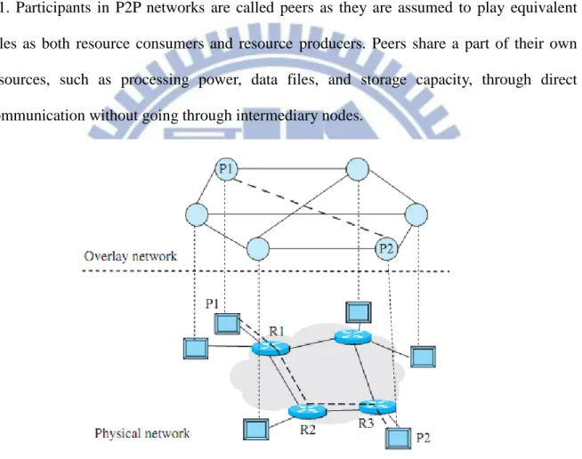
network at the application layer on the top of the underlying IP network, as shown in Figure
1.1. Participants in P2P networks are called peers as they are assumed to play equivalent
roles as both resource consumers and resource producers. Peers share a part of their own
resources, such as processing power, data files, and storage capacity, through direct
communication without going through intermediary nodes.
Figure 1.1: P2P overlay on top of the underlying IP network.
The early application on P2P architecture is file-sharing. Every peer can share its
owned file among peers. Without centralized administration, peers share their own files
more freely. As a result, P2P becomes the best platform on file-sharing. To improve the file
sharing performance on P2P architecture, Bram Cohen invents BitTorrent (BT) [1] which is
many fixed-size chunks so that a peer can download a file from different peers for different
chunks simultaneously. This can improve download speed to a very fast way. The concept of “chunks” causes great effect not only in file-sharing but also in many aspects.
In addition to file-sharing, there were many applications devised based on P2P
architecture, such as Internet Telephony. Skype [5] is probably the most famous VoIP
service so far. It is based on P2P architecture and works under proprietary protocol, which
was a very successful VoIP application on nowadays Internet.
Another popular application based on P2P network architecture is IPTV. IPTV can be
applied on P2P architecture with high scalability and low cost. P2P IPTV can utilize each
peer's upload bandwidth and share its cached contents with other peers. The central server's
load can be reduced to avoid the network bottleneck, and further P2P scheme improves the
system scalability unlike centralized architecture.
The concept of chunk in BT affects P2P IPTV system. The source of video content is
always divided into chunks and delivered to a subset of peers, which receives chunks from
source and shares them with other peers. There are many P2P overlays proposed to achieve
the goal. On the one hand, every peer in tree overlay derives video stream from parent and
delivers contents to its children; On the other hand, every peer in mesh overlay receives
chunks from and delivers chunks to uncertain peers. The mesh overlay is much easier to
implement and robust compared to the tree overlay. However, start-up delay in mesh is
much longer than that in tree [23].
There are few commercial P2P IPTV systems developed in recent years, such
as PPStream [3], PPLive [2], SopCast [6] and TVAnt [7]. These systems attract many users,
and most of them are proprietary systems. They do not release their protocol s and
schemes on their systems, so some researchers are still curious about the inside of these
systems. Works have been done to analyze the system via tracing their packets [11] and we
1.2 Issues
With the popularity of network infrastructure, the efficient and scalable live streaming
overlay construction has become a hot topic recently. Meanwhile, the development of
digitized television enables the media content blessed to be distributed through Internet.
Moreover, with the improvement of upload bandwidth, high-quality video streaming
delivery can be implemented in most of end terminals. For these advantages, IPTV should
be a workable application on P2P overlay1, which has been applied for file sharing, voice communication, group conferencing, and video streaming,
Focus on the application of P2P video streaming, it can be classified into to two
categories. One is video on demand (VoD) and the other is live streaming. Concerning P2P
VoD, scalability and video quality are two significant challenges. The VoD usually provides
the movies or dramas, while live streaming service usually provides the live sports games,
the first-hand stock information, or the latest news. The audiences cannot tolerate any
sensible lags in such live programs. Therefore, in-time requirement of content delivery and
limited availability of future content2 are the most difficult challenges of servicing live streaming. In this paper, we consider and discuss this kind of live streaming.
For network’s aspect, P2P IPTV or live streaming maximizes the delivery quality
to individual peers in a scalable fashion while accommodating the heterogeneity and
asymmetry of access link bandwidth3 and churn4 among participating peers. How to continue the stream smoothly and deliver it efficiently among the peers is important for P2P
live TV. For user’s perspective, every one wishes to interact with the film or other audiences.
1
Due to the limited deployment of IP multicast, application layer multicast has attracted more and more research interests and efforts.
2 In live video streaming, packets are not known a priori, but are created dynamically. 3 The instability of bandwidth becomes a challenging issue for real time applications. 4
He/she can enjoy the customized template of favorite relationship, and creates the
user-generated content to publish on P2P society. One major challenge for P2P streaming is
to offer users satisfactory quality of experience (QoE) in terms of the advanced customized
favorites, and the basic metrics, such as, video resolution, start-up delay, and playback
smoothness.
1.3 Motivation
People watching traditional TV only has to push buttons on the remote control and
wait for less than 1 second to get video showing up. However, a user has to wait for a while
in P2P IPTV for the same action. The duration lasts from few seconds to a couple of
minutes [12] based on the network state and different IPTV systems. In addition, on the
traditional TV system, a user can browse different channels in a few seconds and select a
channel to watch. This feature is not available in IPTV system, especially in P2P IPTV
system.
In live TV environment, the QoE of IPTV service includes convenient user interface,
quality of audio/video, and response time. The switch-delay is one of the most important
factors of QoE. When user is watching a channel and switches to another, it should not take
long time to start. Furthermore, when the network congestion happens or the partner cannot
provide the critical media contents you need immediately, the media player usually has to
stop playing and starts to buffer. Although applying P2P enabled content delivery to IPTV
would provide low latency delivery to requesting customer, channel switching should not
take long time and playback smoothness should be achieved. The problems related to
maintaining quality of experience (QoE) still need to be further explored.
1.4 Goal
to quickly find out the alternative partner when switching channel happens. Since each time
when a user switches the video content, the partner list must be refreshed in order to
connect to the new content providers in the P2P IPTV system. Tracker server is responsible
for providing new partner information to peers when receiving channel-zap messages from
peers. If peers cannot receive the new partners-lists from tracker in time, peers would suffer
from long delay waiting for the new content providers. This is a serious problem resulted in
long switching delay in P2P IPTV more serious than that in the traditional cable TV.
Moreover, due to the lack of key-frame classification during transmitting media data, the
player may suffer the so-called re-buffer event which always makes viewer annoyed and
results in unsmooth playback while watching a program.
To improve P2P IPTV and overcome the problems, we propose new approaches to
reduce the switching delay on mesh P2P network in this thesis, such that a user can
experience P2P IPTV like that in traditional TV.
Playback smoothness is another goal for QoE. The key frames5 of some channels are pre-fetched and updated for a viewable indication periodically in our proposed algorithm. If
key frames are transmitted with the high priority before playback deadline, the users’ QoE
can be improved due to playback continuity. The key frame prefetching usually has the
highest priority in the buffering mechanism. We consider that the key frames are urgent in
the chunk scheduling strategy. Therefore, the chunk with key frame must be pre-fetched by
requesting peers first. Because buffer map is exchanged between peers, each peer quickly
finds available chunks of the same channels among all its neighbors. We measure and
evaluate the switching time and playback continuity, which impact the users’ satisfactions.
The rest of this thesis is organized as follows. We introduce P2P IPTV systems in detail,
including long switching delay problem and re-buffer events in Chapter 2. In Chapter 3, we
discuss our proposed scheme from different point of views. We evaluate our scheme
5
through simulation in Chapter 4. Numerical results and conclusions are stated in Chapter 5
Chapter 2 Background
In this chapter, we briefly describe the P2P IPTV features, focusing on those characteristics that are relevant to this thesis. Next, we discuss the problems of long
switching delay and unsmooth playback. At the end we review some literatures related to
the issues.
2.1 Peer-to-Peer Network
In the traditional network architecture, services must be provisioned by a specific computer which is connected to network with sufficient resources. Usually the machine is
called server, which provides contents such as texts, pictures or multimedia streams which
allow other machines, called clients, to retrieve from. The model in which a client accesses data provided by a server is called client-server architecture.
In the client-server communication model, a server could be a traffic bottleneck of the
service operation. It is not possible for a single server to provide service to a very large
number of clients due to the restriction of resources such as computing power, network
bandwidth, and storage size. Once the server crashes, all services to the client are
terminated. To avoid server failure, the so called server cluster or server farm has been used
to avoid the single point of failure problem. However, as the number of clients becomes
huge, such as the case in Google, Yahoo, and other popular web services, millions of clients
may access the server at the same time, so that thousands of servers are required to provide
the access service. Therefore, the cost of servers in such system would be too high to be
affordable. To reduce the server cost and yet still provide the services to large number of
clients, the so-called Peer-to-Peer (P2P) model was developed in late 1990s. Basically, in P2P network, the role of server is replaced by clients. Actually, the members in a P2P
network play the roles of both a client and a server simultaneously. They provide contents to
and obtain contents from other peers.
2.2 Video Streaming Architecture
The popular network services have been shifted from server based Web, E-Mail to
P2P based VoIP, IPTV, etc. Due to the large volume of streaming video in IPTV, which still
needs further advanced technology to improve the quality of service provisioning. IPTV
becomes the next significant application on Internet. In order to provide TV service on
Internet, the most institutive approach is through centralized server. However, as described
above, client-server architecture has its restrictions. To overcome these drawbacks,
engineer and scientists try to make IPTV provisioning based on P2P architecture. We will
take a close look on the two architectures and its pros and cons in the following
sub-sections.
2.2.1 Centralized server architecture
IPTV based on centralized architecture is very similar to the traditional client-server service. The only difference is that the source server provides video contents
instead of traditional text and images.
However, the IPTV server(s) is unable to accommodate too many viewers
simultaneously. Considering a scenario where few hundreds or even thousands of viewers
intend to watch video stream delivered with a rate 500kbps. The head end of IPTV must
support at least 50Mbps. It is not only a heavy load on both Internet core and source of
IPTV, but also an insufficient way for the resource usage. As a consequence, on
client-server architecture, IPTV has the potential to overwhelm the Internet backbone with its traffic. We need to consider different approaches to overcome the overwhelming
2.2.2 IP layer multicast
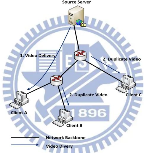
The first idea to overcome the overwhelming problem is to employ IP network
multicast [10] scheme on routers. Figure 2.1 shows the architecture of router multicast
scheme. 1. Video Delivery 2. Duplicate Video 2. Duplicate Video Client A Client B Client C Network Backbone Video Divery Source Server
Figure 2.1: IP layer multicast for video stream delivery.
In Figure 2.1, the source server delivers video streams to a set of viewers, client A, B
and C. Instead of delivering to every viewer a copy of video content, source server only
sends video content to a multicast address. Whenever a peer is interested about some video
content, it registers into the multicast address group. The video content will be duplicated
by router and delivered to every viewer who has joined the group.
issue here. The routers in core network belong to different ISPs. A large portion of them do
not enable router multicast ability nowadays. In addition, the dynamic spanning tree(s)
construction across different subnets is not practical.
2.2.3 P2P architecture
Another method to overcome the overwhelming problem is to minimize the usage of centralized source server(s). Service provisioning of IPTV gradually moves to P2P scheme.
IPTV utilizes the characteristics of P2P, in which every peer downloads and shares video
contents with each other to reduce the load of centralized source server(s). The basic idea is
that source server provides contents to a small subset of peers which again distribute the
received contents to other peers who have requested for the same contents, as shown in
Figure 2.2.
The major difference between this scheme and router multicast is that P2P scheme runs
Video Delivery Overlay Network Peer C Peer A Peer B Peer E Peer D Source Server
Figure 2.2: End system multi-cast on video stream delivery.
Experiment shows that IPTV based on P2P scheme can reduce about 84% of source
upload traffic and only increase 8% of peer upload traffic [16]. As a result, IPTV based on
P2P scheme can significantly increase the scalability and reduce the load of source server(s),
and it is practicable and suitable for large-scale TV multicast.
2.3 Mesh-Based Overlay
The concept of mesh based overlay is very similar to BT mechanism. A newly joined peer in mesh overlay first contacts the tracker server to obtain the list of peers which
either are downloading or have downloaded video chunks. Peers in the system exchange
buffer maps, the availability of chunks, to inform other peers which chunks they have. A
peer’s partners may contain normal peers or server. Therefore, video streams can be delivered to all other peers.
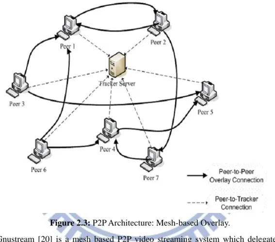
Figure 2.3 shows the mesh-based overlay. The robustness and ease of implementation
should be the biggest advantages of mesh based overlay. Unlike tree-based overlay, the
system neither spends effort to maintain integrity of architecture nor worries about the
joining or leaving of peers. The recovery cost for repairing and maintaining the mesh
overlay is less expensive, so it is much easier to implement and maintain the system.
Figure 2.3: P2P Architecture: Mesh-based Overlay.
Gnustream [20] is a mesh based P2P video streaming system which delegates basic
P2P services to Gnutella. CoolStreaming [21] is a data-driven overlay network for P2P live
media streaming. Media streams are split into fixed-size chunks for delivery. Every peer
owns a 120-bits buffer map for indication of the chunk availability.
The major difference between BT and P2P video streaming application is that the
latter has constrained packet delivery time. If the packet delivery time misses the deadline,
2.3.1 Mesh-based system architecture
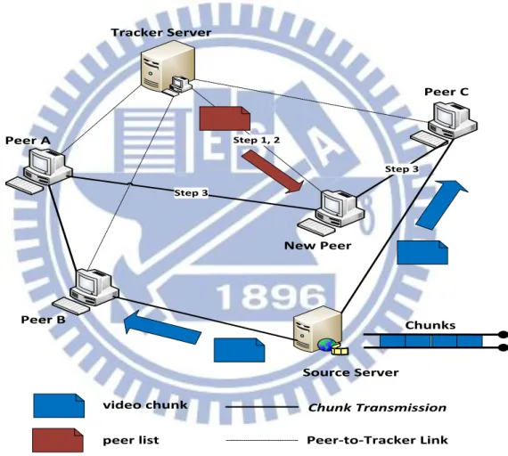
In this section, we describe mesh based overlay system in more detail. As shown in Figure 2.4, the tracker server logs all peers’ information, including IP address, port number,
selected channel, etc. Peers in the system have to keep connection with tracker server and
periodically report their status. The tracker server will kick out those peers that did not
report their status.
Step 1, 2 Step 3 Step 3 Chunks Source Server Peer A Peer B Peer C New Peer Tracker Server video chunk peer list Chunk Transmission Peer-to-Tracker Link
Figure 2.4: Mesh-based system architecture.
In mesh based overlay system, video source server divides video stream into many
chunks with equal size for broadcasting. Whenever a new peer joins the system, the first
step is to connect to tracker server and register its information. After successful registration,
the new peer would select a channel to watch. The tracker server will randomly select a
the Peer List to the new peer, as shown in step 2 in Figure 2.4. The information of peer in
Peer List includes peer’s IP address, port number, and so on. The new peer then establishes the partner relationship with a subset of peers in Peer List, as shown in step 3. In Figure 2.4,
the partners of the new peer are Peer C and Peer A. These peers periodically exchange
buffer map, the availability of chunks, with each other and receive chunks from or transmit chunks to partners. Peers may also establish partner relationship with source server to obtain
fresh video chunks. Using a chunk scheduling algorithm, each peer requests the chunks
required for the coming playback from its partners.
2.3.2 Peer adaptation
After establishing partnership with other peers and starting P2P video streaming
mechanism, a peer may seek more suitable new partners with larger network bandwidth for
improving playback quality. For instance, some partners may leave the system suddenly or
part of network backbone gets broken, these will interrupt the service connection between a
peer and its partner.
The mechanism described above is called Peer Adaptation. The mechanism regarding
how and when to perform peer adaptation is quite different for various P2P video streaming
systems.
2.4 Mesh-Based Software Components
Figure 2.5 shows the mesh based system software components. The peer software
components include media player and P2P streaming engine. The streaming engine is the
main component on peer software which is a cooperator on media player and partners on
network wide. Streaming engine has to collect chunks from partners or provide chunks to
2.4.1 P2P streaming engine
The P2P streaming engine is the core of peer software which has to (1) Receive chunks or share chunks with partners; (2) Exchange buffer maps with partners for
indication of chunks a peer currently buffered; (3) Duplicate media chunks to media player
for playback.
A peer can request buffer map from its current partners and requests chunks from partners who advertised the buffer map. After downloading the chunks, P2P streaming
engine stores them in chunk buffer, as depicted in Figure 2.5. P2P streaming engine also has
the responsibility to select which peer to download chunks and which chunk needs to be
downloaded. The kind of operation is called chunk scheduling, and there are many
scheduling algorithms designed for it such as deadline-first and slow-bandwidth first.
Selecting a new partner to establish partnership in case of churn or insufficient upload
Media Player Media Player
Media Plyer
P2P Streaming Engine
Peer Peer Peer Peer Peer
Partners
Figure 2.5: Mesh-based software components.
2.4.2 Media player
Media player is used for playback media which is sent by the streaming engine. Firstly, media player sends an HTTP request to the streaming engine, which then converts video
chunks into a file with the format that media player can recognize. Before playback, media
player always needs to buffer a short interval of media for playback continuity concern. If
the chunk did not arrive before playback deadline, it will result in gaps6 on media playback. Note that the uncompleted chunk can also be converted into media stream but with low or
even bad quality during playback.
6
2.4.3 Tracker
A tracker is a server that assists the communication between peers which use the streaming service. Once peers enter the P2P streaming network, the first action for them to
do is registering themselves to the tracker server so that tracker can realize what video
content you want to watch and inform other peers your existence. However, it is the major
critical point as clients are required to communicate with the tracker to initiate the
downloading. Clients that have already begun downloading also communicate with the
tracker periodically to negotiate with newer peers and provide statistics to the tracker.
2.5 MPEG-4
One of the most significant improvements in video compression has been the MPEG suite of standards [19], of which MPEG-4 is the newest. MPEG-4 encodes an input stream
into a sequence of frames known as GOPs. The main concept here is that, from one frame
or picture to the next, very few changes may occur in the short time between frames. Due to
the minor differences between frames, it is possible to predict the changes from one scene to
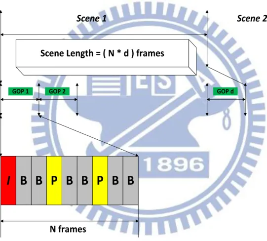
the next. Basically, there are three types of frame in MPEG-4, and they are I, P, and B frame
respectively. Figure 2.6 illustrates how a GOP is further decomposed into anywhere from 9
to 15 frames, labeled as I, B, and P. These individual MPEG-4 frames are what comprise the
original video after it has been compressed.
A brief discussion of individual frames is given below.
1) I (intra coded picture): This is single still compressed image that is used as a starting
point for the next sequence of frames (B and P types). This single image is also used to resynchronize the entire scene. In the event that a GoP is lost or corrupted, the next GoP
has a fresh image from which it may start. There are no references to other pictures in I
is the largest among the tree types of frames.
2) P (predicted pictures): These are pictures that are compressed and used as a reference
point for B frames. The changes from the I frame to the next P frame and then to the next frame are used to compress the overall GoP.
3) B (bi-predictive pictures): These provide the highest level of compression. The B frame
may be predicted by using both the forward and backward directional changes in
motion.
I B B P B B P B B
Scene Length = ( N * d ) frames
Scene 1
Scene 2
GOP 1 GOP 2 GOP d
N frames
Figure 2.6: Scene is broken down into a GOP.
In summary, I frame is a reference point used to start the next GOP and to
resynchronize the video during errors in transmission. The P frames are compressed
versions of I frame, and they contain some predicted information. The B frames are
compressed even further and are comprised mostly of predicted information from
neighboring I and P frames. All of these frames are related, and each I frame has several P
frames up to the next I frame are of no use.
2.6 Channel Switching Delay and Playback Continuity
The traditional cable television (CATV) has its own broadcasting system. Video service provider broadcasts every channel’s contents through private cable network without
any digital data. Therefore, when people turn on the television, they can immediately watch
the video content without any delay. Most importantly, there is almost no playback latency
in switching channels.
The channel switch delay in P2P IPTV system defines that it is the time between a user
switching to another video program and the first show up of the target video frame. The
main reason of long channel switching delay is the time to refresh peers’ partners. This
process must be assisted by the tracker server as shown in Figure 2.7. Meanwhile, if peers
can successfully find out their new partners, they may spend time downloading and
buffering enough video chunks before playback. Unfortunately, P2P video streaming systems always need to buffer more video contents compared to original client-server
architecture due to peer’s dynamic behavior, that is, peers join or leave the system randomly.
In addition, the mesh overlay system has longer switching delay because the peer in mesh
based overlay have no specific video content source and need to pay more time on seeking
and determining the content source. How to reduce channel switching delay becomes a
serious issue in mesh based P2P IPTV system. The behavior on switching video channel is
something like restarting the video stream. Peer application has to re-cache the video stream
Peer 4 Peer 5 Peer 2 Peer 1 Streaming server Tracker Streaming server Peer 6 Peer 7 Peer 3
When Peer 3 switches its channel Step 1: get new peer list from
tracker
Step 2: close the connections of the former partners
Step 3: Establish the connections to new partners
Figure 2.7: When switching channels, the first action to do is asking the tracker for
the new peer list.
Another important measure of service quality of a streaming system is the
continuity of video playback at the user hosts. Re-buffer event is a problem that
concerns QoE. As mentioned in the previous section, I frame in the MPEG-4 codec is
an independent decoding unit. If the lack of I frame occurs when player’s starting to
decode, the playback would stop during viewer’s watching and player has to buffer
waiting for the coming of decoding unit. Re-buffer event is one of the measured target
Table 2.1: Re-buffer event.
2.7 Related Works
Recently, there has been several papers published concerning about how to reduce the
channel zapping time in IPTV system. In other words, how to reduce the channel zapping
time is equal to how to quickly find peer’s partner when switching to another channel or
video program that other peer currently watches.
Hyunchul et al proposed an IPTV channel control algorithm [15] by adjusting the
number of broadcasting channels that are located close to users over IP networks and the
number of additional I-frames are inserted into each channel, based on the user’s channel
preference information. Uran et al presents hybrid schemes that combine channel
prefetching and reordering scheme [13]. Additionally, in an attempt to remotely monitor the
network-wide quality in mesh-pull P2P live streaming systems, Xiaojun et al process the
harvested buffer maps and present results for network-wide playback continuity, startup
latency, playback lags among peers, and chunk propagation pattern [14].
Xiaojun also collected extensive packet traces for various different measurement
scenarios, including both campus access networks and residential access networks [11]. The
measurement results bring important insights into P2P IPTV systems. Moreover, their
results show the following. 1) P2P IPTV users have similar viewing behaviors as regular TV
users. 2) During its session, a peer exchanges video data dynamically with a large number
of peers. 3) A small set of super peers act as video proxy and contribute significantly to
video data uploading. 4) Users in the measured P2P IPTV system still suffer from long
Some works still involve layer video in peer-to-peer streaming. Hao Hu adopt scalable
video coding (SVC) in P2P streaming [18], and he develops utility maximization models to
understand the interplay between efficiency, fairness and incentive in layered P2P streaming.
Furthermore, Xin et al proposed a new scheduling approach for layered video streaming,
called LayerP2P. LayerP2P is implemented in the PDEPS Project in China, which is
expected to be the first practical layered streaming system for education in peer-to-peer
Chapter 3 Proposed Scheme
As mentioned in previous chapters, IPTV based on P2P network overlay requires longer start-up delay than that in client-server architecture to satisfy video playback quality
when peers switching their video contents or channels. Long switching delay problem is
much serious in mesh based P2P network overlay because whenever switching channel
happens, peers must inform tracker their new target channel, meanwhile, to refresh the
partner list in the peer side, tracker has the responsibility to select the partners for the new
video content and send back to the peers. This involves a lot of messages passing and is a
time-consuming process, which is the main cause of long switching delay. Moreover, the
playback smoothness is one of the problem which affect user’s Quality of Experience
(QoE).
In this thesis, we focus on the long switching delay problem in mesh based P2P IPTV
because mesh is the major P2P architecture in current market and its long switching delay is
more serious than others. We will describe our proposed scheme in detail in the following
sections.
3.1 Design Philosophy
To reduce the long switching delay, the most intuitive idea is to reduce the time finding new partners who exactly have the chunks of your zapping channel. Normally, the list of the
new partner information is rendered by the tracker, which will find candidates of partners
and send the partner list back to the client, the client then select the target partners from the
list. This duration is the main cause of switching delay. Therefore, if tracker can provide
some partner lists of other TV channels beforehand, client can directly connect to the target
and manage them becomes another important issue in this thesis.
3.2 Main Scheme
We claim that there are three phases in the P2P IPTV application. These are Ready,
Start-Up and Play phases.
Figure 3.1: The three phases of peer application.
Users who intend to watch TV on the Internet will launch the P2P IPTV application,
and when the user interface appears, the application has entered the “Ready” state waiting
for user’s input to decide what they want to watch. After selecting the channel and push the
start button, the application enters the Start-Up state. The first task peer application has to
do is caching enough video in the buffer in start-up phase for playing back. Peer application
then transfers from Start-Up to Play phase after collecting enough video contents in the
buffer. In Play phase, peer application performs normal P2P IPTV function, receives chunks
from and transmits chunks to partners. If peer application switched to another channel, it
may go back to Ready phase and shut down the application.
In the following subsections we describe our proposed approaches in more detail. We
propose two mechanisms to improve QoE. One is reducing the channel switching delay via
Channel Monitoring, and the other is increasing the playback smoothness during the
watching. The former is through pre-caching some partner lists of other channels. The latter
is a method of preventing from suspension through prefetching the chunk of key frames.
3.2.1 Channel Monitor
Four types of surfing behavior
In this section, we propose a method to reduce the channel switching delay in P2P
IPTV system. Every time peers login into a P2P IPTV system watching their selected
channels, the tracker server not only provides partner list for them but also records the
watching time of their surfing contents and put into database as shown in Figure 3.2.
0 50 100 150 200 250 台視 HBO 中天娛樂 LEE Mike Nemo Baros Sam
Member ID: NEMO Password: ****** Member ID: LEE
Password : ******
Member ID: Baros Password: ******
Member ID: Sam Password: ******
Member ID: Mike Password: ******
Figure 3.2: Preferred channels of each user in the tracker server.
their surfing behavior. We assume that user has four types of surfing behavior such as
up/down, favorites, and toggle. Sometimes viewers tend to keep pushing buttons to change
channels. Relative to watching-channel, tracker can infer the next channel which viewers
may switch to as Expected-Channel. The expected channel would be an up channel when
pushing the up button, a down channel when pushing the down button, and the previous
channel when pushing the toggle button. Moreover, according to number of times viewers’
surfing, tracker also adds up three longest watching time of surfing channels as
Preference-Channel. Josh Miranda Sam Mike Nemo
Figure 3.3: Expected- Channels and Preference-Channels.
Each time when switching channel happens, the first thing to do is sending a message
regarding their leaving from original TV content and refreshing peers’ partner lists. After
tracker server receives the channel-switching notification, it then provides the designated
peer list to peers in order for them to connect to and download video data. The less time
channel switches, the more desire the user will keep using this service. Therefore, we intend
to reduce the time for peers to regain the new peer lists, that is to say, peer can directly
connect to the designated partners. In this thesis, we create a new module named Channel
Monitor in Peer application that will pre-collect viewers’ peer list based on Expected-Channels and Preference-Channels from tracker server before viewers switch their channels.
Table Management
The first time peers enter a P2P streaming network, peers will login registering to
tracker regarding which channels they want to watch. At this moment, tracker’s
responsibility is to provide peer list of currently watching channel for them. When applying
Channel Monitor to peer application, the tracker not only offers the peer list of watching channel but also consults its database according to viewer’s ID and password and offers
other peer lists of his specific channels mentioned before. Channel Monitor maintains a
table to record the information. Moreover, once Channel Monitor obtains the peer lists, it
must periodically queries tracker server to refresh its table in case that there may have some
peers leaving or joining the P2P network or even some peers have switched their watching
channels. This procedure is to retain the correctness of Channel Monitor so that we can
Start
Send message to tracker for monitoring channels
Extract the peer lists of
Expected-Channels and
Preference-Channels
The members of up-channel change ? The members of down-channel change ? The members of toggle-channel change ? The members of prefer-channels change ? End
Update peer list of up-channel
Update peer list of down-channel
Update peer list of toggle-channel
Update peer list of prefer-channels YES YES YES YES NO NO NO Accept channel-related message from
tracker?
YES
NO
Table Structure
Assume there are M channels or M movies in our P2P IPTV system. In this case,
there will be M entries in Channel Monitor. The table structure is illustrated in Figure
3.5. The index in the table represents the channel number and each entry is composed
of one list which records the partners’ information. The index number, for instance K,
following the list represents that those peers in the list are currently watching channel
K. According to user’s surfing behavior mentioned above, different peer has different
Expected-Channels and Preference-Channels. Therefore, the table in the Channel-Monitor is different among peers in P2P IPTV system. No doubt, there may some interactions among some viewers due to the similar interests of surfing behavior.
Peer B Peer A Peer E Peer C Peer D watching Up Down Preference 1 Preference 2 Preference 3 toggle E D C B A A ~ Z : Peer ID Internet G K I H S L V N Q T R M X P Z Y F J W O P U
There is one problem we like to address here. Although Channel Monitor has provided
some peer lists of other channels from tracker server beforehand. There are still chances that
peer may not succeed in finding designated peers to connect due to the situation that those
peers have left the P2P network or switched to other channels but Channel Monitor cannot
obtain the latest partner lists from the tracker. In this case, peers have to re-send the query
message to tracker. In order to overcome this problem and enhance the hit ratio when
switching occurs, for each partners list in the table, the default member of the list in the
Channel Monitor is assigned source server which has all the video chunks as the first partner. Moreover, in addition to the lists of Expected-Channels and Preference-Channels
which is applied in this method, other channels excluding Expected-Channels and
Preference-Channels are assigned source server as their only partner depicted in Figure 3.6. Therefore, we don’t worry about the miss rate of Channel Monitor because peers always
have at least one partner to download video chunks even though they switch to a channel
watching Up Down Toggle Preference 1 Preference 2 Preference 3 A B C D E F G H I J K L M N O P Q R S T U Assign Server as the first partner
Figure 3.6: Server as the first partner.
3.2.2 GOP Map
As described earlier, we would like to maximize the amount of data that a viewer can
download, as this minimizes the probability of glitches during regular playback and reduce
the startup time when a user switches to another channel or movie. However, if the stream
for the chunk being viewed is received with insufficient bandwidth or the requesting peer
are facing insufficient downloading bandwidth due to the existing of multiple TCP
connections. In this situation, the most crucial components of a picture, such as MPEG
I-frames, must be delivered to the client immediately so as to reduce the impact of playback
un-smoothness which is called re-buffer event, and maintain continuity during viewer’s
watching.
mentioned in the Chapter 2, the picture is composed of several GOPs and the size of GOP is
equal when it is encoded by the server. The size of GOP depends on the encoder.
Traditionally, peers in P2P streaming system will exchange so-called “Buffer Map” with
their partners to realize what chunks other peers currently cached. Each chunk has its
sequence number. However, we cannot realize what the chunks are stored inside such as
I-frame, P-frame, or B-frame. In MPEG-4, I-frame can be independently decoded and
synchronized in one GOP, that is to say, B and P-frames can only be decoded with the
I-frame in the same GOP. If media player cannot receive the I-frame in time according the
sequence number of chunk, the other received B or P frames are useless in its associated
GOP. Normally, this is the main cause which makes the playback pause. To overcome this
problem, we designed a data structure called GOP Map which is similar to the original
buffer map except that GOP Map can make peers realize the position of I frame in the
Exchange 0 time O ff set BM Width BM playable video I GOP Map Buffer Map One-to -One Mappi ing I
Figure 3.7: GOP Map.
Chunk with I frame
Normally, video stream are divided into fixed-sized chunk in P2P IPTV system. In our
thesis, we define one chunk contains only one frame type. That is, the size of chunk is
different according to the frame type within it. Therefore, source server can produce GOP
Map according to the size of each chunk and provide this information to the first peer that connects to it.
The function of GOP Map
The function of the traditional buffer map is to provide the currently cached chunks to
peer’s partners, while the GOP Map aims to indicate whether the chunk has I frame or not.
However, the chunk which contains I frame is not necessarily cached by peers. Therefore, if
peer wants to know the currently cached chunks of his partners, this job can be succeeded
partners, and for every cached chunks, we check the GOP Map. Then, we can find out the
designated chunk with I frame and begin downloading. Furthermore, the GOP Map has
one-to-one mapping with the original buffer map. In other words, the width of GOP Map is
the same as the original buffer map. The “one” in each entry indicates that the chunk now
possesses I frame is in it, while the “zero” means no I frame existed. Owing to the GOP
Map, the buffer map messages exchanged between peers must be adjusted to include the GOP Map information. However, because of the similarity of two data structures, the differences compared with the original buffer map message are the new string of zeros and
ones which is used to decide the position of I frame data and a flag which is used to indicate
whether to include this information when exchanging messages with partners or not. After
peers received the new buffer map message, the module of scheduling manager can extract
the string of GOP Map and make decision to fetch the required chunks.
Relay Peer Video Stream II I Media schedule 13 10 11 12 15 16 ... 13 14 ... I I I I I I I I time P2P Network
Figure 3.8: Buffer map and GOP map.
Pre-fetching chunks in P2P streaming system indeed brings advantages of receiving
additional chunks other than the chunks in the sliding window when peer has sufficient
bandwidth. But we ignore the frame type when sequential pre-fetching is in progress. As long as the active pre-fetching module do buffer some chunks before the playback position
of the video, however, according to the decoding dependency of MPEG-4 codec, I frame is
a single still compressed image that is used as a starting point for the next sequence of
frames (B and P types). This single image is also used to resynchronize the entire scene. If those cached chunks do not contain any I frames or if I frame is lost, the following B and P
frames before the next GOP are of no use due to the decoding dependency on the I frame. In
other words, even peers’ prefetching mechanism continue to work and to pre-fetch chunks
with frames of B and P types, the media player still cannot decode without I frame in one
GOP. In this situation, peer must consider the frame type when applying pre-fetching
mechanism to enhance the playback smoothness. GOP Map plays an important role in
dealing with this issue when pre-fetching is in progress. The GOP Map in each peer will
help pre-fetch module explicitly realize which chunks contain I frame by the sequence
number. The scheduling manager can then pre-fetch the closest chunk possessing I frame in
the next GOP. Moreover, due to the help of GOP Map, whenever scheduling manager wants
to fetch the chunk indexed by buffer offset, it can also search for the next chunk containing
I frame and pre-fetch it. In the following, we can describe pre-fetching algorithm step by
step.
Step1: For each partner, check their buffer map, if one of its partner has the chunk
indexed by buffer offset, fetch it.
Step2: Check GOP Map from the current offset, when encountering the first marked
entry, record the sequence number as “pre-fetch_next_I” .
Step 3: Check the buffer, if there is no cached chunk whose sequence number is equal
prefetch_next_I, pre-fetch it.
From the perspective of pre-fetch mechanism, we can quickly collect the chunks
containing I frame from different peers in the P2P IPTV system via the help of the new data
structure as shown in Figure 3.9.
Peer A Peer B Peer C Peer D Peer E Offset I GOP = I B B P B B ( size = 6 ) Pre-fetch_next_I = 6; Fetch chunk 3 and chunk 6 !
... 3 6 ... 3 4 5 6 ... ... 3 4 5 6 ... ... 3 4 5 6 ... ... 3 4 5 6 ... ... 9 10 11 12 ... ... 12 ... ... 3 4 5 6 ... ... 3 4 5 6 ... Cached Chunk I frame chunk Relay ... 3 4 5 6 ... ... 3 4 5 6 ... Buffer Map GOP Map Buffer Map GOP Map Buffer Map GOP Map Buffer Map GOP Map Buffer Map GOP Map 6 Pr e-fe tch ch un k 6 3 Ch un k 3 ... 3 4 5 6 ... GOP Map
Figure 3.9: Fetch and pre-fetch.
Assume that the framing sequence for one GOP: I B B P B B P B B P B B P B B, and
one chunk contains only one frame type of video data. An illustrating example is depicted in
Figure 3.10. We assume that the scheduling manager now fetches the chunk with sequence
number 23. When it starts to fetch chunk 24, the pre-fetch module begins to inspect the
GOP Map. According to the above algorithm, the pre-fetch module then decides the sequence number of pre-fetched chunk and pre-fetches it. We don’t pre-fetch too many
fetching the chunks containing B and P types of frames without the decoding I frame, which
causes the waste of the bandwidth and the severe problem of unsmooth playback.
... 23 24 25 26 27 28 29 30 31 32 33 34 15 35 GOP 2 GOP 3 ... 44 45 14 BM Offset 23 ... 29 30 31 32 ... GOP Map ... 24~29 I
Figure 3.10: An illustrative example.
Pseudo-code algorithm of pre-fetch mechanism
In order to give a better understanding of what we mentioned about pre-fetching the
Prefetch_Next_I(GOP_Map, offset)
Input : An Boolean array GOP_Map, and an integer offset Output : An integer of prefetch sequence number
1 k ß length[GOP_Map] 2 do for i ß offset to k 3 do if ( GOP_Map[ i ] = true ) 4 then return i 5 end if 6 end for 7 return -1
Table 3.1: Pseudo-code of pre-fetch mechanism.
3.3 Software Viewpoint
In this section, we will evaluate our mechanism from software point of view. This can improve reader’s understanding of our proposed schemes in different aspects. We will demonstrate the skeleton of tracker server and peer application software along with Channel
3.3.1 The algorithm of tracker server
Tracker Server Pseudo-Code Infinite Loop{
switch( New_Event){
case Peer_list_request : …
case Erase :
Check the channel Table and find out the position of peer;
delete the id of designated peer; inform other members that the list has been changed;
case Channel zap list:
send the new peer lists to the requesting peer;
update table and inform other peers on the list; case … :
… }
}
3.3.2 The algorithm of peer application
Peer Application Pseudo Code Infinite Loop{
switch(New Event){
case Register to tracker: …
case Check Buffer : …
case Chunk Request : { for each partner
do check partner’s buffer map ;
if the chunk of sequence number indexed by buffer offset exists then send message to the partner;
}
case Pre-fetch Next I : {
check GOP Map, determine the pre-fetch_Sequence_number; for each partner
do if the chunk of pre-fetch_Sequence_number exists then send message to the partner;
}
case Channel zap : {
erase all the members in the partner list;
consult the Channel Monitor whether the partner list of target channel exists;
if new partner list is presented in the Channel Monitor then establish the connections with those new partners; exchange buffer map and GOP map;
}
case …: … } }
Table 3.3: Pseudo code of peer application.
Table 3.3 shows the algorithm of peer application’s behavior in pseudo code. We
present only part of it including chunk request, pre-fetch chunk with I frame, and when
channel zapping happens. Instead of asking peer lists from the tracker, a peer can directly
consult the module Channel Monitor. Therefore, peer can directly connect to the target
3.3.3 The algorithm of channel monitor
Channel Monitor Pseudo code Infinite Loop {
switch(New Event){ case MONITOR:
periodically send messages to tracker for new status of Expected-Channels and Preference-Channels;
case CHANNELS:
If tracker replies updating message, then update the corresponding entry in Channel
Monitor;
else the entries of Expected-Channels and Preference-Channels do not change, there is no need to update the Channel Monitor ; …
} }
Table 3.4: Pseudo code of Channel Monitor.
Table 3.4 shows the algorithm of Channel Monitor in pseudo code. The main job of
Channel Monitor is periodically monitoring the status of currently watching channels from tracker in P2P IPTV system. If there is any status change regarding peers’ watching, leaving
or joining on the tracker site, tracker would reply the updating message to Channel Monitor.
3.4 Summary
The module Channel Monitor allows peers to collect some other partners-lists before peers switch their channels at any time. If peer happens to switch to the channel in the
Expected-Channels or in the Preference-Channels, he can directly establish the connections to those cached peers and begins downloading. Even though switching to other channels not
in the Expected-Channels and Preference-Channels, Channel Monitor still provide source
the P2P IPTV system. Additionally, exchanging the new data structure GOP Map among
peers can make pre-fetch mechanism more efficient and accurate because peers need to
pre-fetch the key frame to prevent the re-buffer event. Besides pros mentioned in the previous sections, our proposed schemes feature the following benefits:
1. Reduce the switch delay due to the assistance of Channel Monitor.
2. Avoid heavy loading on tracker when a large number of peers want to switch their
channels simultaneously.
3. GOP Map with the mechanism pre-fetch I frame of the next GOP can reduce the
number of occurrence called re-buffer event.