CR AP3 r CR cloud CSS engine S/RPM database Binding cache SS agent SM agent Home agent
C
OGNITIVE
R
ADIO
N
ETWORKS
: A P
RACTICAL
P
ERSPECTIVE
S
AU-H
SUANW
U, H
SI-L
UC
HAO, C
HUN-H
SIENK
O, S
HANG-R
UM
O, C
HUNG-T
INGJ
IANG,
T
ZUNG-L
INL
I, C
HUNG-C
HIEHC
HENG,
ANDC
HIAU-F
ENGL
IANG,
N
ATIONALC
HIAOT
UNGU
NIVERSITYA C
LOUD
M
ODEL AND
C
ONCEPT
P
ROTOTYPE FOR
C
OGNITIVE
R
ADIO
N
ETWORKS
C
OGNITIVE
R
ADIO
C
LOUD
N
ETWORKING
S
ERVICE
The concept of cognitive radio (CR) was first introduced by Joseph Mitola III in [1]. Under the framework of CR, non-licensed users (sec-ondary users, SUs) can access the channels for original licensed users (primary users, PUs) if the quality of service (QoS) to PUs can be effec-tively preserved or guaranteed. In view of the inefficient usages of some legacy spectrum hold-ers (less than 25 percent overall according to [2]), CR is expected to resolve part of the spec-trum shortage issues in wireless metropolitan and local area networks (MANs/LANs).
Over the past decade, extensive research has been done on CR in either theoretic explo-rations or circuit designs. The termination of
analog TV broadcasting allows the Federal Com-munications Commission (FCC) of the United States to take an initiative to test the CR con-cept in its TV spectrum in parts of its spaces when there are no TVs signal coverage (also referred to as TV white space, TVWS) [3]. The first TVWS service, provided by Spectrum Bridge Inc., is approved for field trials by the FCC in Wilmington, North Carolina, and autho-rized for commercial operations in January 2012. Encouraged by the FCC’s CR policy, interna-tional organizations have started to define CR standards in TVWS (e.g., IEEE 802.22 and 802.11af).
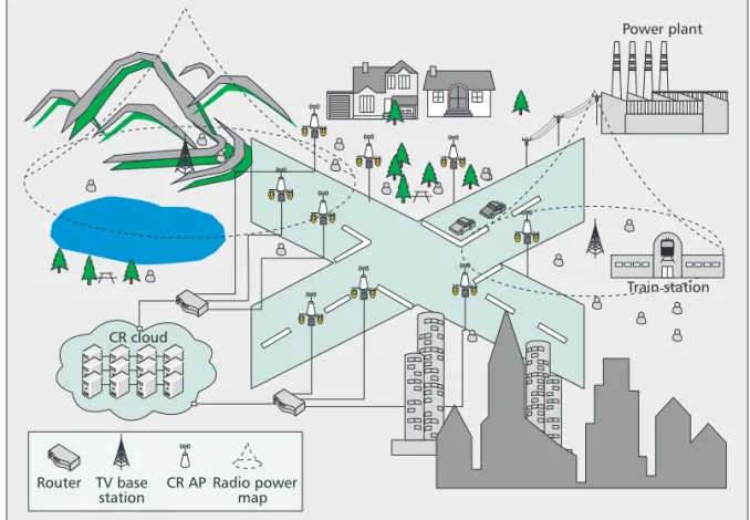
Evolving from CR in TVWS, the concept has developed into a new paradigm of intelligent communications that encompass ideas such as spectrum sharing, competition, and reconfig-urable and heterogeneous radio networks. These kinds of diverse and dynamic radio services rely on a computing infrastructure that is ubiquitous and elastic, yet has virtually unlimited resources to collect, analyze, process, and coordinate the massive and dynamic radio communications activities. Thanks to the rapid growth of cloud computing and fiber-to-the-home (FTTH) Inter-net services, one can start to imagine a future wireless city where seamless CR services provid-ed by pervasive access points (APs) and cloud computing are as common as streetlighting ser-vices provided by ubiquitous lamps and power plants, as shown in Fig. 1. With such CR cloud networking (CRCN) service, the public can get seamless and free baseline wireless access to the Internet avenue just like walking in a city street at night without worrying about the light. As a mat-ter of fact, many cities in the world (e.g. Lon-don, Beijing, and Taipei) have started to provide the public free Wi-Fi services at hot spots. To support dynamic and seamless CR access, as well as envisioning the great impact brought about by CRCN services, we present herein a primitive CRCN prototype and operating model that inte-grate functions of cooperative spectrum sensing (CSS), dynamic spectrum access (DSA), and mobility management on a unified cloud plat-form. The proposed CRCN infrastructure is illustrated in Fig. 2.
A
BSTRACT
The FCC’s approval for the first commercial operation in TV white space gives new momen-tum to the development of cognitive radio in TVWS. On the other hand, the rapid growth of Cloud computing makes it possible and more economical to build a CR metropolitan area net-work with commodity hardware. In view of the opportunity and challenges brought about by these two technologies, we propose a CR cloud networking model that is able to support CR access in TVWS. Making use of the flexible and vast computing capacity of the cloud, a database and a cooperative spectrum sensing algorithm that estimates the radio power map of licensed users are realized on a CR cloud implemented with Microsoft’s Windows Azure Cloud platform. The CRC can support CSS, dynamic spectrum access and mobility management. A medium access control protocol is also developed for this CRCN model to collect sensing reports and pro-vide access to the TVWS and CRC services. Through this CRCN prototype, important net-work parameters such as the mean squared errors in CSS, the CR channel vacating delay, and the cloud-based handover time are measured for the design and deployment of the CRCN concept.
The authors propose
a CR Cloud
Network-ing model that is
able to support CR
access in TVWS.
Making use of the
flexible and vast
computing capacity
of the Cloud, a
database and a
cooperative spectrum
sensing algorithm
are realized on a CR
Cloud (CRC)
imple-mented with
Microsoft’s Windows
Azure Cloud
platform.
C
OGNITIVER
ADIOC
LOUDN
ETWORKINGA
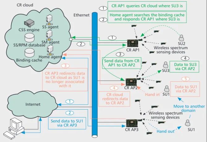
RCHITECTURE The CRCN architecture is mainly based on a CR cloud (CRC) and distributed CR APs that are connected to the CRC via an Internet back-bone. The spectrum sensing (SS) agent at the CRC collects SS reports from CR APs or wire-less sensing devices (SDs) that are associated with the APs, and drives a CSS engine to recon-struct the radio power map (RPM) of PUs’ spec-trum based on the SS reports and a sparse Bayesian learning (SBL) algorithm [4].Upon requests for channel access from CR APs, the spectrum management (SM) agent at the CRC checks the RPM database and allo-cates appropriate spectra to the CR APs accord-ing to their locations and the spectrum white spaces in the RPM. The CR APs therefore coor-dinate both the SS reports from SDs as well as the DSA of SUs in the prototyped CRCN archi-tecture. A CR medium access control (MAC) protocol that carries these two types of functions is introduced later in this article.
When connecting to the CRCN, an SU is first associated with a CR AP through a dedicated control channel. The CR AP then assigns, through the control channel as well, the SU a data channel and registers the SU to the home agent of the CRC. The home agent maintains a list of CR AP-SU pairs in the binding cache of the CRC. This binding cache allows the home agent to establish end-to-end connections between CR SUs. This type of channel access and data exchange process is illustrated with a packet delivery flow from SU2 to SU3 in Fig. 2. To ensure the access rights of PUs, the CR APs regularly check the SM agent about the
avail-ability of their data channels, and will reassign SUs’ channels if necessary.
In another scenario where a regular Internet user wants to get connected to an SU in the CRCN, the user also needs to query the home agent of the CRC to establish the connection. In addition to these typical CR services, a cloud-based mobility management service is also pro-vided in the CRCN. Specifically, when a CR AP receives packets that belong to an SU that is no longer associated with it, it will redirect the data packets to the home agent of the CRC. The home agent temporarily stores the data in the binding cache of the CRC. When the SU gets re-associated with a CR AP, the home agent updates its CR AP-SU list, and redirects the packets to the SU through its new associated AP. This cloud-based mobility management is illustrated with a data redirecting flow in the lower part of Fig. 2. The entire procedure for the cloud-based DSA and mobility management is specified in detail later.
C
OMPARISONS OFC
OGNITIVER
ADIOP
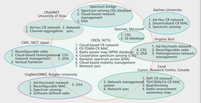
ROTOTYPES To differentiate our proposed CRCN from exist-ing CR prototypes, a Venn diagram in Fig. 3 is used to summarize and contrast the functions of various CR prototypes in the world. Since the proposal of the idea of CR [1], there have been numerous prototypes built to study feasible CR functions and services. What is shown in Fig. 3 is only an indicative and representative list due to space limitations. Four of them are prototypes by academia, and the other four are built by industry or government-funded research insti-tutes. All these prototypes provide certain kinds of SS capabilities, and most consider ad-hoc CR networks, e.g. the CRaMNET by the UniversityFigure 1. A cognitive radio cloud networking (CRCN) service model in TV white space.
Power plant Router TV base station CR AP Radio power map Train station CR cloud
In another scenario
where a regular
Internet user wants
to get connected to
an SU in the CRCN,
the user also needs
to query the home
agent of the CRC to
establish the
connec-tion. In addition to
these typical CR
ser-vices, a Cloud-based
mobility
manage-ment service is also
provided in the
CRCN.
of Oulu, Finland [5], the CogNet/Orbit projects done by WINLAB, Rutgers University, United States [6], and other prototypes by Virginia Tech, United States [7] and Aachen University, Germany [8].
Even though there have also been some other prototypes or technologies for infrastructure-based CR networks, such as Coral designed by the Communications Research Centre, Canada [9], the Authorized Shared Access (ASA) service provided by Spectrum Bridge [10], and the cog-nitive wireless clouds (CWCs) proposed by Japan’s National Institute of Information and Communications Technology (NICT) [11], a CR testbed that integrates the functions of CSS, DSA, and network and mobility management on a unified commercial cloud platform has not been developed to the best of our knowledge. These, however, are key functions for all the dif-ferent types of CR prototypes in Fig. 3. In the CRCN service model illustrated in Fig. 1, one can imagine that a huge computing resource will be required to support the massive and dynamic interactions between CR SUs/SDs and the RPM database, CSS engine, and other network man-agement units/agents of the CRC. The perfor-mance of a CRCN architecture like Fig. 2 will be determined by its scalability and the access time of cloud services, as well as the processing and networking delays inside the cloud. These moti-vate us to develop a CR prototype to study the feasibility of the CRCN concept. The prototype is developed based on Microsoft’s Windows Azure to provide CRC services, and Rice Uni-versity’s Wireless Access Research Platform (WARP) [12] to implement the functions of a CR AP. An embedded Linux operating system is also ported onto the WARP to provide Internet
connectivity and realize a CR-MAC protocol. Important functions and features of our CRCN prototype are summarized below:
• A CRC implemented on Microsoft’s Windows Azure
–SS agent, database, and CSS engine to com-pute RPM and provide radio environment awareness
–SM agent and RPM database for DSA of SUs
–Home agent and binding cache for network and mobility management
• A CSS engine to reconstruct the RPM of PUs –A CSS algorithm based on a sparse Bayesian
learning (SBL) algorithm
–A MapReduce-like programming model to support scalable computation for CSS
–Estimation of the number, locations, and radiated power propagation of PUs
• A cloud-based CR-MAC protocol
–Coordination of SDs, and collection of SS reports
–Frequency-division and time-division multiple access (FD/TDMA)
–DSA of SUs
• A CR research platform that provides radio access, distributed SS and CRC services –CR APs, each integrating one control
chan-nel and seven data chanchan-nels on a Linux-enriched WARP
–A vector signal generator to generate digital TV signals in UHF band, 782~928 MHz –TI’s CC1111 to provide control and data
channels access, each with bandwidth up to 115.2 kHz
–Hope radio frequency’s (RF’s) wireless SDs provide distributed readings of received signal strength indicators (RSSIs)
Figure 2. The prototyped CRCN architecture.
SU2 SU3 Wireless spectrum sensing devices SU1 Wireless spectrum sensing devices SU1 CR AP1 CR AP2 CR AP3 Ethernet 2 4 2 1 1 3 3 5 4
CR AP1 queries CR cloud where SU3 is Home agent searches the binding cache
and responds CR AP1 where SU3 is
Data to SU3 via CR AP2
1
2 Send data to SU1
via CR AP3
Move to another domain CR AP3 redirects data
to CR cloud as SU1 is no longer associated
with it Data to SU1
via CR AP2 Hand in Hand out CR cloud redirects data to CR AP2 CR cloud CSS engine SS/RPM database Binding cache Internet SS agent SM agent Home agent
Send data from CR AP1 to CR AP2
Taking CR in TVWS
as an example, to
ensure the received
signal quality of TV
sets, the FCC
requires CR operators
able to access
databases that can
provide the RPM of
TV signals with a
sensitivity of
0.8dBm below the
noise level.
In the sequel, we start to introduce the need for CSS and an SBL-based CSS algorithm that lays the foundation for CR services. A CR-MAC protocol that supports CSS and DSA in the CRCN is presented later, followed by a network-ing procedure designed to link the CR SUs/SDs, APs, and CRC services.
A S
PARSE
B
AYESIAN
L
EARNING
M
ETHOD
FOR
C
OOPERATIVE
S
PECTRUM
S
ENSING
The CSS scheme implemented in this prototype is aimed to reconstruct the RPM of TV broad-casting or signals from rival CR operators. Tak-ing CR in TVWS as an example, to ensure the received signal quality of TV sets, the FCC requires that CR operators be able to access databases that can provide the RPM of TV sig-nals with a sensitivity of 0.8 dBm below the noise level (–106.2 dBm). In addition, a database also needs to provide the geographical locations of TV base stations (BSs), their heights above the terrain, antenna patterns, radiation powers, chan-nel numbers, and call signs. SUs use the databas-es to determine their accdatabas-ess rights in TVWS. To achieve these multiple purposes of CR databases in TVWS, some research units (e.g., Microsoft Labs) have started to develop databases (Spec-net) that make use of location-based CSS.
Although the geographical locations and some other parameters of TV BSs are stationary and may be available, it remains difficult to reconstruct the composite RPM of individual BSs that are broadcasting signals, as well as their corresponding radiation powers and propagation decays in different places. The problem becomes even more challenging when it comes to esti-mate the PRMs of more dynamic rival CR oper-ators. Therefore, a CSS scheme that makes use of SS reports collected from distributed SDs or SUs are in fact necessary. The reasons are at least twofold: First, the radiation power of a TV BS typically covers a much larger area which is beyond the reach of the transmit power of a
sensing or mobile device. To reconstruct the RPM of even a TV BS requires sensing reports from SDs located in different places inside the TV signal’s coverage range. Considering the much weaker transmit power (50 mW) of a TVWS SD, it requires many CR APs in the same area to collect the sensing reports from distribut-ed SDs. The CR APs then send the SS reports to the SS database on the CRC for CSS engines to reconstruct the RPM of the TV signal.
Second, it is also necessary to estimate the signal coverage ranges of CR APs and SUs from rival CR networks to make the most out of TVWS. Even if the signal coverage ranges of such TV band devices (TVBDs) are much small-er than that of a TV BS, they are more dynamic and overlapping to some extent such that their composite RPMs may have different shapes and vary frequently. These two important features of CR in TVWS have attracted significant research attention in CSS. To handle the massive SS reports and overcome the algorithm complexity in reconstructing the RPMs of TV BSs or TVBDs, we propose a computational framework for CSS under the CRCN architecture in Fig. 2. The CSS method only requires the positions and RSSI readings collected from SDs or SUs. Con-sidering that the positions and population densi-ties of CR SDs/SUs are supposed to be random and may vary in different times and areas, we develop an SBL-based CSS algorithm on Microsoft’s Windows Azure cloud platform. With the scalability of cloud computing, the pro-posed method is in principle able to do CSS with sparse sensing reports over a huge area. More details about the operating procedure of the CSS algorithm are provided below [4, 15].
CSS
WITHS
PARSE ANDR
ANDOMLYD
ISTRIBUTEDSS R
EPORTS Assume that there are N SDs or SUs in an area of Np¥ Npwhere there are Mpactive PUs. TheRSSI vector r = [r1, r-,…, rN]Tcollected from the
SDs or SUs at the positions of Z = [z1, z2,…, zN]
Figure 3. Function comparisons of various CR prototypes in the world.
Aachen University CRaMNET
University of Oulu
CWC, NICT, Japan
CogNet/ORBIT, Rutgers University
Spectrum bridge Virginia Tech Specnet, Microsoft CRCN, NCTU 1. Ad-Hoc CR network 2. Decentralized CR MAC 3. Spectrum sensing 1. Ad-Hoc/mesh network 2. Reconfigurable radio 3. Heterogeneous network management 1. Ad-Hoc/mesh network 2. Reconfigurable MAC 3. Spectrum sensing 4. Software defined radio
1. WiFi CR network 2. TD/CSMA/CA CR MAC 3. Beamforming 4. Radio environment awareness map 5. Network management system 6. Network sync 1. Cloud-based CR network 2. FD-TDMA CR MAC
3. Radio power map (RPM) database 4. Cooperative spectrum sensing (CSS) 5. Dynamic spectrum access (DSA) 6. Cloud-based mobility management 7. Network sync 4. CSS 5. DSA 4. CSS 5. DSA 5. DSA 1. CSS 2. SS database 1. Reconfigurable radio 2. Cloud-based heterogeneous network management 3. Vertical handover 1. Ad-hoc CR network
2. Channel aggregation3. Network sync
1. Spectrum sensing (SS) database 2. Cloud-based network management 3. DSA
Coral
Comm. Research Centre, Canada
Considering that the
positions and the
population densities
of CR SDs/SUs are
supposed to be
random and may
vary in different
times and areas, we
develop a SBL-based
CSS algorithm on
Microsoft’s Windows
Azure Cloud
platform.
in this area, with zi∫ [xi, yi]Tbeing the 2D
coor-dinates of the ith RSSI reading, are fed back to the CRC by their associated CR APs. The RSSI vector r in decibels (dB) is modeled in a linear regression form of
r =DYw + u, (1)
where w is an M¥ 1 weighting vector, and Y ∫ [j1(Z), …, jM(Z)] is a N¥ M matrix defined by
the values jj(Z) ∫ [jj(z1), …, jj(zN)]Tof the
basis functions jj, j = 1, … M, evaluated at the
locations of z1, z2, …, zNfrom which the N RSSI
readings are collected.
This regression model 1 is intended to fit the N collected RSSI readings with a weighted linear combination of the M basis vectors, jj(Z);
there-by one can estimate the RPM, Yw, and hence the number of active PUs, their corresponding positions, radiation powers, and propagation loss models. More specifically, the basis functions, jj (zi), j = 1, …, M, are defined in a form of
(2) attempting to approximate the standard radia-tion power loss model of
Pr=DPt– PL
——
(d0) – 10n[log(d) – log(d0)] (dB) (3) with adjustable parameters cj∫ [cj,x, cj,y]Tand sj
that characterize the locations and power decay-ing rate of PUs’ signal sources. The parameter Pr
in Eq. 3 is the signal power received in dB at a propagation distance, d, from the signal source; Ptstands for the source radiation power; PL
—— (d0)
is the signal power observed at a reference dis-tance, d0, and n is the path loss exponent at which the radiation power decreases with the propagation distance d. On the other hand, the N¥ 1 uncertainty vector u models the logarithms of the shadowing effects at the N different col-lection sites, and is thus considered a zero-mean and white Gaussian random vector with variance equal to b–1, denoted by N(0, b–1I
N).
The objective of CSS is therefore to estimate the weighting vector, w, the parameters C = [c1, …, cM] and s = [s1, …, sM] of the basis functions,
and the exact values of M from the sparse mea-surements r collected at the locations Z. If the estimates are accurate enough, one can expect that approximates the number of active PUs that transmit signals at c^
j, j = 1, …, M^, with radiation
power equal to w^
j/2s^j(dB), respectively.
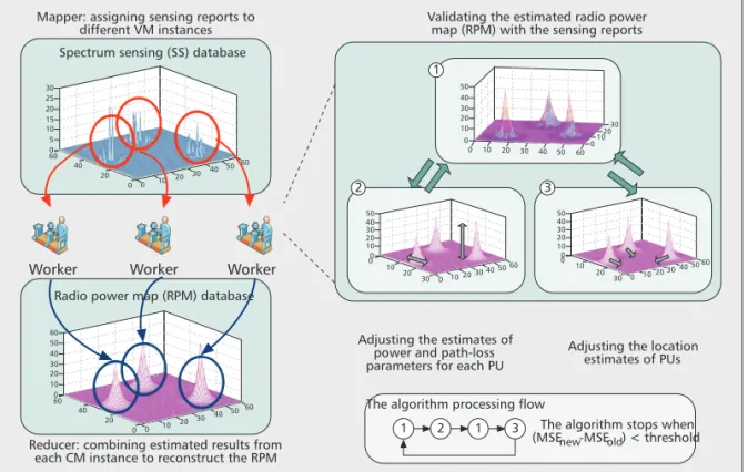
The entire problem appears to be a compli-cated estimation problem, and is thus parti-tioned into several subproblems to approach the solutions in an alternative and iterative manner under the Bayesian inference framework [4]. Specifically, the estimation problem is executed in three steps:
1. Estimate w and b, given the estimates of C^, s^,
and M^.
2. Delete unnecessary bases and update the esti-mate M^based on C^, s^, and the new estimates
w ^and b^. 3. Adjust c^
jand s^jof the survival bases, given M^,
w
^and b^, and stop if ln{P(r˜w^, C^, s^, b^, M^)}
converges. Otherwise, go back to Eq. 1. Under the CRCN architecture in Fig. 2, the SBL-based CSS algorithm is implemented on Windows Azure with a MapReduce-like pro-gramming model [14, 15]. The input SS data from CR APs are first processed by the SS agent and stored in different tables of the SS database according to their locations. The CSS
ϕj i j i j x i j y j z s x c y c s ( ) 1 exp ( , ) ( , ) 2 2 2 − − + − ⎧ ⎨ ⎪ ⎩⎪ ⎫ ⎬ ⎪ ⎭⎪⎪
Figure 4. Illustrations of a sparse Bayesian learning procedure for RPM reconstruction.
Adjusting the location estimates of PUs Adjusting the estimates of
power and path-loss parameters for each PU
Worker Worker Worker
1 2
2 3
1
1 3
The algorithm processing flow
Validating the estimated radio power map (RPM) with the sensing reports Mapper: assigning sensing reports to
different VM instances
Reducer: combining estimated results from each CM instance to reconstruct the RPM
The algorithm stops when (MSEnew-MSEold) < threshold Radio power map (RPM) database
10 0 10 010 2030 20 30 40 50 0 40 50 0 30 20 10 10 0 40 50 0 20 30 40 50 60 30 20 10 10 0 10 0 20 30 20 30 40 5060 20 30 0 102030 40 50 60 25 30 20 15 10 5 0 40 20 10 60 20 30 40 5060 0 0 50 60 40 30 20 10 0 40 20 0 0 10 60 20 30 40 5060 Spectrum sensing (SS) database
The cloud-based CR
MAC protocol in this
prototype aims at
collecting SS reports
and coordinating
channel accesses
among SUs and SDs.
From the aspect of
commercialization of
TVWS and CR, one
big step, but not the
only step, is the
progress of the IEEE
802.11af standard.
engine, which is formed with a set of virtual machines (VMs), is activated periodically by the SS agent to estimate w^, C^, s^, b^, and M^in
parallel with data in each table, following steps 1 to 3. The aforementioned estimates are stored back to the RPM database, and then used to reconstruct the RPM, Y (C^, s^)w^, to be used by the SM agent. The entire procedure is illustrat-ed in Fig. 4.
C
LOUD
-B
ASED
CR MAC P
ROTOCOL
The cloud-based CR MAC protocol in this prototype aims at collecting SS reports and coordinating channel accesses among SUs and SDs. From the aspect of commercialization of TVWS and CR, one big step, nut not the only step, is the progress of IEEE 802.11af stan-dard. Taking IEEE 802.11af as an example, on the TVWS side, channel bandwidth is 6 MHz, and available channels may not be contiguous; on the WiFi side, associated users share a channel in a time-division multiple access man-ner. We, thus, design and implement a fre-quency-division and time-division multiple access (FD-TDMA) MAC protocol for our CRCN prototype.
In our design, TVWS channels assigned to a CR AP are partitioned into one control and multiple data channels. The control channel is for the CR AP to collect sensing reports and coordinate data channel accesses; the data channels are assigned to SUs for data deliver-ies. Multiple SUs can be assigned to different data channels or share the same channel in a TDMA manner. SDs and SUs always listen to the control channel unless they are requested t o p e r f o r m c h a n n e l s e n s i n g o r g r a n t e d t o deliver data. In the following, we first intro-duce the frame structure designed for CSS and channel access, followed by the detailed operations.
F
RAMING ANDF
RAMEF
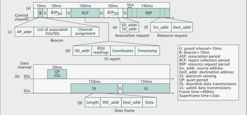
ORMATSIn the proposed CR-MAC, time is framed, and several frames are grouped into a superframe. For simplicity, we only show one data channel in a time frame in Fig. 5. Each frame on the con-trol channel consists of five fields: Beacon (B), ASsociation Period for SUs (ASPSU), Report Collection Period (RCP), ASsociation Period for SDs (ASPSD), and Resource Request Period (RRP), as shown in Fig. 5a. In our implementa-tion, considering the hardware constraints and synchronization precision, we insert a 10ms guard time between two consecutive fields. On the other hand, a frame on the data channel has three fields: Quiet Period (QP), DownLink data transmissions (DL), and UpLink data transmis-sions (UL), as shown in Fig. 5b. Similarly, a guard time is inserted between DL and UL fields.
In our design, CR APs periodically broadcast beacons on the control channel to announce their existence and manage channel activities, and SUs or SDs must associate and synchronize with a CR AP before accessing channels or per-forming SS. As a result, a control frame starts with a beacon, which consists of three fields: CR AP address (AddrAP), the list of associated SUs and SDs, and data channel assignments (Fig. 5c). Moreover, ASPSUand ASPSD are for SUs and SDs to send association requests to their intend-ed CR APs, respectively. Both fields are dividintend-ed into time slots, and adopt a contention-based multiple access scheme.
Each time slot of ASPSUor ASPSDexactly accommodates an association request, which contains the issued SU’s or SD’s address (Fig. 5e). The CR AP utilizes the RCP to poll the associated SDs for SS results, while SDs utilize the RRP to send resource requests to the CR AP. A sensing report contains the information of the SD’s address, measured RSSI readings of
Figure 5. Framing and the five defined frame formats of the proposed CR MAC protocol.
G: guard interval=10ms B: beacon=10ms ASP: association period RCP: report collection period RRP: resource request period Src_addr: source address Dest_addr: destination address SS: spectrum sensing
QP: quiet period
DL: downlink data transmissions UL: uplink data transmissions Frame time=400ms
Superframe time=2sec SD_addr/
SU_addr Src_addr Dest_addr Association request Resource request (a)
(c)
(b)
(e)
SD_addr readingsRSSI Coordinates Timestamp SS report Beacon Data channel 50ms SDs QP (SS) (d)
Length SRC_addr Dest_addr Data Data frame
(g)
(f) AP_addr List of associatedSUs/SDs assignmentChannel
B G ASPSU... G RCP G ASPSD... G RRP... Control channel 100ms Slot 140ms 50ms 10ms 50ms 150ms SUs DL 150ms UL G
data channels, coordinates, and timestamp (Fig. 5d). Similarly to ASPSUand ASPSD, the RRP is time-slotted, and a resource request contains the issuing SU’s address, denoted Src_addr, and the intended SU’s address, denoted Dest_addr, as shown in Fig. 5f.
Upon association, an SD hops to and senses data channels sequentially in the QP. To accu-rately detect PUs’ activities on data channels, all SUs are forbidden to transmit data in this time duration. Following the QP, the DL and UL periods are, respectively, for a CR AP to transceive data to and from it scheduled SUs. A data packet consists of packet length in byte (Length), Src_addr, Dest_addr, and data payload (Data), shown in Fig. 5g. The defined acronyms and abbreviations in the CR-MAC are summa-rized in a table in Fig. 5 as well.
P
ROTOCOLO
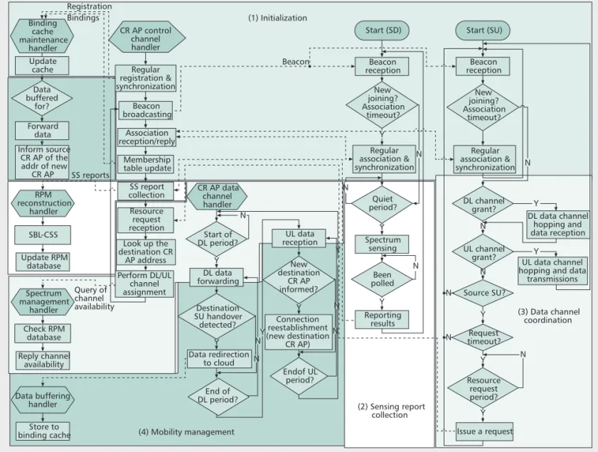
PERATIONSThe proposed cloud-based CR-MAC protocol coordinates network components of CRC, CR APs, SDs, and SUs to complete the four func-tioning phases of the CRCN, including initializa-tion, SS report collecinitializa-tion, channel access coordination, and cloud-based mobility manage-ment. To describe and depict the intertwined relationship between the network components
and functions, the control flows of different components are shown in separate flowcharts in Fig. 6, each started with a handler. Furthermore, the functioning phases, which involve interac-tions among multiple components, are marked with different background colors in the figure, and separated from each other with small spac-ings. The solid lines represent the control flow in a management function of a network compo-nent, while the dashed lines depict the relation-ship of triggering events between network components. The details of the four functioning phases are described below.
Initialization — The initialization procedure is
summarized in Fig. 6 (1). When connecting to the CRCN, CR APs, SUs, and SDs first perform registration/association and time synchroniza-tion. Indeed, CR APs send registration requests to the home agent in the CRC. Upon receiving registration requests, the home agent updates the binding cache correspondingly, and replies to the CR APs with the timestamp. The registered CR APs now are able to broadcast beacons and start to serve SUs.
For a new joining SU (or SD), when hearing a beacon, it will send an association request to the CR AP in a randomly selected time slot of
Figure 6. The flowchart of the designed cloud-based CR-MAC protocol.
N Inform source CR AP of the addr of new CR AP Membership table update Association reception/reply End of DL period? (4) Mobility management (2) Sensing report collection DL data forwarding Data redirection to cloud Been polled Spectrum sensing Reporting results Y Issue a request DL channel grant? UL channel grant? Regular association & synchronization N N N N N N N N N N Y Y Resource request period? Y Y N Source SU? N Request timeout? Y Y Y Y Y Y Y Y DL data channel hopping and data reception UL data channel hopping and data
transmissions (3) Data channel coordination Start (SU) Beacon reception New joining? Association timeout? Quiet period? Start of DL period? Regular association & synchronization Start (SD) Registration Bindings SS reports Query of channel availability Beacon (1) Initialization Beacon reception New joining? Association timeout? UL data reception Connection reestablishment (new destination CR AP) New destination CR AP informed? Endof UL period? CR AP data channel handler Regular registration & synchronization CR AP control channel handler Update RPM database SBL-CSS RPM reconstruction handler Reply channel availability Check RPM database Spectrum management handler Store to binding cache Data buffering handler Binding cache maintenance handler Destination SU handover detected? SS report collection Resource request reception Look up the destination CR AP address Update cache Forward data Data buffered for? N Perform DL/UL channel assignment Beacon broadcasting
the ASPSU(or ASPSD). Similar to the CRC, the CR AP maintains a membership table to record the associated SUs’ and SDs’ addresses. It fur-ther forwards the address information of its associated SUs to the home agent for communi-cation establishment and mobility management. Note that the association relationship between CR APs and SUs is also maintained in the bind-ing cache. The association process is successful if the SU (or SD) is listed in the “associated SUs and SDs” of the next beacon. Otherwise, the SU or SD keeps sending association requests in the following control frames. After being associated, SDs and SUs can start to perform SS and request resources on demand, respectively, under the coordination of the CR AP.
Both membership table and binding cache adopt a “soft-state” approach for dynamic mem-bership and network topology changes. That is, CR APs, SUs, and SDs periodically send regis-tration/association requests to refresh their membership. The corresponding entries in the membership table and binding cache will be removed after timeout.
Sensing Report Collection — The procedure of SS
report collection is summarized in Fig. 6 (2). Associated SDs synchronously and sequentially sense all data channels in the QP. Note that in the QP, although associated SUs cannot transmit data on data channels, new joining SUs are allowed to perform association on the control channel. After sensing, the SDs hop back to the control channel and wait for the CR AP’s polling to report their sensing results in the RCP. The reason for adopting proactive polling is that SDs are deployed for SS and reporting only; thus, a polling mechanism can significantly increase the flexibility of SD sampling and the accuracy of RPM reconstruction.
The CR AP forwards the gathered sensing reports to the SS agent in the CRC via the Inter-net backbone. The SS agent then drives the CSS engine to derive the RPM of PUs and updates the RPM database.
Channel Access Coordination — Although associated,
an SU cannot access any data channel unless it gets a grant. Therefore, when an associated SU wants to initiate a data communication (in the following, we call it source SU), it first sends a resource request, which is with a timer, to its CR AP (here we name it source CR AP) in a ran-domly selected time slot of the RRP. The source CR AP then queries the SM agent in the CRC about the available data channels. The SM agent, after checking the RPM database, replies to the source with the CR AP the allocated data chan-nels. The source CR AP then performs channel assignment for UL transmissions.
To establish the end-to-end data path, the source CR AP then looks up its membership table to discover whether the intended destina-tion SU is also associated with itself. The source CR AP also performs DL channel assignment if the destination SU is associated with itself. It informs both the source and destination SUs of the allocated channels in the next beacon.
On the other hand, if the destination SU is not under its coordination, the source CR AP
queries the home agent in the CRC about the destination SU’s associated CR AP (here we name it destination CR AP). Upon knowing the address of the destination CR AP, the source CR AP not only notifies the source SU of the assigned data channel for UL transmissions, but also forwards received data frames to the desti-nation CR AP. The destidesti-nation CR AP is responsible to further deliver data frames to the destination SU by allocating a DL data channel. It may occur that the intended destination SU is unknown to the CRCN. In such a situation, the source CR AP will not grant the source SU’s resource request. The procedure of sensing report collection is summarized in Fig. 6 (3).
To protect the access rights of PUs, CR APs regularly query the SM agent about the availabil-ity of their allocated data channels. SUs vacate the assigned data channels when either finishing data transmissions or PUs are detected. For the latter, the CR APs will assign another available data channels to the SUs for the remaining data transmissions.
Cloud-Based Mobility Management — Considering
that a destination SU re-associates with another CR AP (in the following, we call it new destina-tion CR AP) due to mobility, the source CR AP is not aware of this change, and keeps forward-ing data frames to the original destination CR AP (here we name it “old destination CR AP”). One unique feature of the prototyped CR-MAC protocol is the cloud-based mobility manage-ment.
The procedure of mobility management is summarized in Fig. 6 (4). Because of the “soft-state” table maintenance approach, the old des-tination CR AP will discover that the desdes-tination SU is no longer under its management. It then redirects all received data frames, which are des-tined to the destination SU, to the home agent in the CRC for temporarily buffering. When the link of the new destination CR AP and the desti-nation SU is updated, the home agent delivers all buffered data frames to the destination SU. Besides, the home agent informs the source CR AP of the address of the new destination CR AP. From now on, the source CR AP delivers data frames directly to the new destination CR AP.
A CRCN P
ROTOTYPE AND
E
XPERIMENT
R
ESULTS
Experimental results on the CRCN prototype are presented in this section. The experimental setting is as shown in Fig. 2. The CRC is imple-mented on Windows Azure, with the databases built with SQL Azure. On the other hand, CR APs are implemented with WARPs [12], and SUs and SDs use TI’s transceiver modules CC1111 and the HM-TR transceiver modules of HOPERF [13], respectively, to communicate with WARPs. There are 10 SDs, 2 SUs, and 2 CR APs in the experimental CRCN prototype.
To avoid interfering with TV signals, the fre-quency channels used in experiments are set in the industrial, scientific, and medical (ISM) bands right above the UHF TV band. The
con-To establish the
end-to-end data path, the
source CR AP then
looks up its
member-ship table to discover
whether the
intend-ed destination SU is
also associated with
itself. The source CR
AP also performs DL
channel assignment
if the destination SU
is associated with
itself.
trol channels used for each CR AP are set at the 866 and 868 MHz bands, and the data channels are set at the 870 and 872 MHz bands with data rates equal to 115.2 kb/s.
In this CRCN prototype, the frame time is 400ms; a superframe consists of five frames so that its duration is 2 s. The time settings for each field in a control frame and a data frame are shown in Fig. 5. The HM-TR of an SD spends 20 ms on sensing a data channel; thus, it can sense two data channels in a QP. Besides, a CR AP can poll five HM-TRs to collect reports and forward the collected reports to the SS agent in a frame. In our design, a CR AP queries the SM agent about the availability of its allocated data channels once per superframe (indeed, at the beginning of the last frame in a superframe). The superframe time is set to meet the FCC’s requirement to vacate a channel within 2 s when its PU is detected.
R
OBUSTNESS OF THEP
ROPOSEDSBL-B
ASEDCSS S
CHEME In the experiments, there is only one PU BS in a designated area. The PU’s frequency is set at 870 MHz. And SSs are done by SDs whose RSSI readings only consist of five strength levels, cor-responding to: Level 1: –96.2 dBm~–87.1 dBm Level 2: –87.1 dBm~–78.6 dBm Level 3: –78.6 dBm~–71.2 dBm Level 4: –71.2 dBm~–61.0 dBm Level 5: –61.0 dBm~To conduct experiments in a constrained lab space, the transmission power of the PU BS is set to the same order of the CR AP such that the RPM of a PU BS can be reconstructed with the sensing reports of the 10 SDs. This setting not only simplifies the complexity of experi-ments, but also helps assess the robustness of the proposed SBL-based CSS algorithm as there are now only 10 SDs whose RSSI readings are partitioned only into 5 levels in a wide range of signal strengths from –96 to –61 dBm. Experi-mental results show that the mean squared error in the estimated PU location becomes negligible when the number of SDs exceeds 8. And the missing ratio is less than 0.1 when the number of SDs is greater than 4. Both results show that the proposed SBL-based CSS algorithm is quite robust even with a limited number of imprecise sensing measurements.
R
ESPONSET
IME OFC
HANNELV
ACATING INCRCN
Channel vacating time is the elapsed time from the presence of a PU to the SU’s release of the PU’s occupied channel. Several factors may affect the channel vacating time, such as network communication delays, the time to read/write databases, and the execution time of the CSS algorithm. Based on our measurements, the min-imum, average, and maximum round-trip net-work delays between the CR AP and the CRC are (4.1, 4.2, 5.7) ms, respectively. Besides, the three-tuples of the (minimum, average, maxi-mum) computation times for performing the CSS algorithm are (0.27, 0.54, 0.91) s,respective-ly. The three-tuples of spending times for the SS agent to write the SS database and for the SM agent to read the RPM database are (0.15, 0.31, 0.66) s and (0.11, 0.31, 0.92) s, respectively. As a result, the CRC processing delays, which are sums of these above network and processing delays, fall within [0.5341, 2.4957] s.
In addition to the CRC processing delays, channel vacating time also depends on PUs’ presence times as SS is performed once per superframe. More specifically, the SS reports are sent back by the CR AP in the end of the RCP of each frame (Fig. 5a). Besides, the CR AP queries the CRC for channels’ availability at the end of the beacon period of the last frame of a superframe, and updates its channel usage in the first beacon period at the beginning of a super-frame. Consequently, if a PU appears right before the first QP of a superframe, and its radio signal gets sensed and processed by the CRC right after the first RCP with a minimum amount of time (0.5341 s), the CRC is aware of the PU’s presence before the CR AP’s inquiry in the very same superframe. As a result, the PU’s channel will be released by the CR AP in the first beacon period of the next superframe, end-ing up with a shortest channel vacatend-ing time of 1.98 s.
On the contrary, if a PU appears right after the first QP of a superframe, its radio signal will be sent and processed by the CRC only after the first RCP of the next superframe. The waiting time will become 2.11 s. Moreover, if the CRC in this case happens to spend a maximum amount of time (2.4957 s) in processing the SS reports, the CRC will not be aware of the PU’s presence before the CR AP’s inquiry for channel status in the same superframe. As a result, the PU’s channel will not be released by the CR AP until the first beacon of the fourth superframe, ending up with a longest channel vacating time of 5.92 s. We note that in practice, the overall channel vacating time might also be slightly affected by the processing time of the CR AP.
T
HEC
LOUD-B
ASEDH
ANDOVERT
IME INCRCN
In this experiment, we estimate the time spent to hand over data destined to a mobile SU from one CR AP to another. The handover time is mainly determined by the round-trip network delays between APs and the CRC, whose three-tuples of (min, average, max) times are (4.1, 4.2, 5.7) ms; the time to save the redirected data to the binding cache and update the offline status of the intended SU at the home agent, whose (min, average, max) times are (62.5, 70.8, 93.7) ms; as well as the time to retrieve the redirected data from the binding cache and look up the address of the SU’s new associated CR AP, whose (min, average, max) times are (151, 204, 343.7) ms. As a result, ignoring the processing time for CR APs to handle the data, the mini-mum, average, and maximum handover times out of 1000 runs are 218 ms, 279 ms, and 443 ms, respectively.Based on the experimental results, we observed that in general cases, the measured handover time matches the 400 ms frame time. That is, if an SU moves away from one CR AP and gets re-associated with another CR AP in a
Channel vacating
time is the elapsed
time from the
pres-ence of a PU to the
SU’s release of the
PU’s occupied
chan-nel. Several factors
may affect the
chan-nel vacating time,
such as the network
communication
delays, the time to
read/write
databas-es, and the
execu-tion time of the CSS
algorithm.
MAC frame, the CRC can redirect data from its previous CR AP to its current one in the next MAC frame. Moreover, we found that data retrieval and address lookup times dominate the worst case handover time. To reduce the worst case handover time in order to match the frame time, we may employ a more efficient searching algorithm in the CRC.
C
ONCLUSIONS
We introduce a concept prototype of a CRCN model and evaluate the time to perform CSS, CR channel vacating, and handover in a CRC implemented with Microsoft’s Windows Azure cloud platform. Experimental results showed that the proposed SBL-based CSS algorithm performs well even with a limited number of imprecise sensing measurements. Although the overall system response time is slightly longer than the FCC’s policy to access the TVWS, it could effectively be improved with some system adjustments and more advanced searching algo-rithms. Despite the fact that the true CRCN sys-tem performance will only be available after large volume tests, the experimental results did reveal that the proposed CRCN concept is a promising technique that might open up a new CR networking model. More advanced studies such as scalable cloud-based CSS schemes and CR resource management methods remain cru-cial to justify the feasibility of such a CRCN con-cept in the support of large-volume public access.
A
CKNOWLEDGEMENTThis work was supported in part by the National Science Council, Taiwan under Grant NSC 99-3113-P-009-004.
R
EFERENCES[1] J. Mitola and G. Q. Maguire, “Cognitive Radio: Making Software Radios More Personal,” IEEE Pers. Commun., vol. 6, no. 4, Aug. 1999, pp. 13–18.
[2] M. A. McHenry, NSF Spectrum Occupancy
Measure-ments Project Summary, Shared Spectrum Co. Report,
Aug. 2005.
[3] FCC, Second Report and Order and Memorandum Opin-ion and Order, FCC 08-260, Nov. 2008.
[4] D.-H. T. Huang, S.-H. Wu, and P.-H. Wang, “Cooperative Spectrum Sensing and Locationing: A Sparse Bayesian Learning Approach,” Proc. IEEE GLOBECOM, Miami, FL, Dec. 2010.
[5] R. Sathyanarayana et al., “CRaMNET: Opportunistic Cognitive Radio for MANET with Adaptive PHY and Dynamic Routing Capability,” SDR-09 Technical Conf., Washington DC, Dec. 2009.
[6] D. Raychaudhuri et al., “CogNet — An Architectural Foundation for Experimental Cognitive Radio Networks Within the Future Internet,” Proc. ACM MobiArch, Dec. 2006.
[7] F. Ge et al., “A Heterogeneous Cognitive Radio Network Enabling Dissimilar Cooperative Spectrum Sensing, Dynamic Spectrum Access, and Interoperability,” Proc.
IEEE DySPAN, Chicago, IL, Oct. 2008.
[8] J. Ansari et al., “A Flexible MAC Development Frame-work for Cognitive Radio Systems,” Proc. IEEE WCNC, Quintana Rao, Mexico, Mar. 2011.
[9] J. Sydor et al., “Cognitive, Radio-Aware, Low-Cost (CORAL) Research Platform,” Proc. IEEE DySPAN, May 2010.
[10] Spectrum Bridge, Authorized Shared Access (ASA), http://www.spectrumbridge.com.
[11] H. Harada et al., “A Software Defined Cognitive Radio System: Cognitive Wireless Clouds,” Proc. IEEE
GLOBE-COM, Washington, DC, Nov. 2007.
[12] WARP Repository, http://warp.rice.edu/trac.
[13] HOPERF, HM-TR Series UHF Wireless Transparent Data Transceiver, HOPERF Co., June 2008.
[14] J. Dean and S. Ghemawat, “MapReduce: Simplified Data Processing on Large Clusters,” Commun. ACM, vol. 51, no. 1, Jan. 2008, pp. 107–13.
[15] C.-H. Ko, D.-H. T. Huang and S.-H. Wu, “Cooperative Spectrum Sensing in TV White Spaces: When Cognitive Radio Meets Cloud,” Proc. IEEE INFOCOM, Shanghai, China, Apr. 2011.
B
IOGRAPHIESSAU-HSUANWU([email protected]) received B.S. and M.S. degrees from National Cheng Kung University, Tai-wan in 1990 and 1993, respectively, both in engineering sci-ence. From 1993 to 1995 he served in the Army of Taiwan, and from 1995 to 1999 he worked as a circuit and system design engineer in Taiwan. In 2003 he received a Ph.D. degree in electrical engineering from the University of Southern California, Los Angeles. From 2003 to 2004 he was a postdoctoral research fellow at the Department of Electri-cal Engineering, University of Southern California. From 2004 to 2005 he served as a technical consultant for Winbond Electronics Corporation America, developing wireless MIMO-OFDM products. Since 2005 he has been an assistant profes-sor at the Department of Electrical and Computer Engineering, National Chiao Tung University (NCTU), Taiwan. His research interests lie in the application of signal process-ing theory to wireless communication systems.
HSI-LUCHAO([email protected]) received her Ph.D. degree in electrical engineering from National Taiwan Uni-versity in 2004. Since August 2004 she has been an assis-tant professor, Department of Computer Science, NCTU. Her research interests lie in the area of design and perfor-mance analysis of wireless networks, including MAC and resource management in cognitive radio networks, millime-terwave personal area networks, and LTE/LTE-A networks. CHUN-HSIENKO([email protected]) received his B.S. degree from NCTU in 2010. Since September 2010, he has been a Ph.D. student in the Institute of Communications Engineering, NCTU. His research interests include machine learning and a parallel framework for cloud computing. SHANG-RUMO([email protected]) is a Mas-ter’s student in the Institute of Computer Science and Engi-neering, NCTU. His research interests include cloud computing and resource allocation in cognitive radio networks.
CH U N G-TI N GJI A N G ([email protected])
received his B.S. degree in Communication Engineering from NCTU in 2009. Since September 2009 he has been a Ph.D. student in the Institute of Communications Engineer-ing, NCTU. His research interests include LDPC coding and reconfigurable radio.
TZUNG-LINLI([email protected]) received his B.S. degree from National Central University (NCU), Taiwan, in 2010. He is now a master student in the Institute of Com-puter Science and Engineering at NCTU. His research focus-es on the dfocus-esign and implementation of control channels for cognitive radio networks.
CHUNG-CHIEHCHENG[StM] (james770329.cm99g@nctu. edu.tw) received his B.S. degree in communication engi-neering from NCTU in 2010. He is currently a Master’s stu-dent in Institute of Communications Engineering, NCTU, Taiwan. His research interests lie in the embedded system design and power management for cognitive radio net-works.
CHIAU-FENGLIANG([email protected]) received his B.S. degree in computer science and information engi-neering from NCU in 2010. He is now a Master’s student in the Institute of Network Engineering, NCTU. He research focuses on the design of scheduling algorithms for cogni-tive radio networks.