A Study of Optimal Mould Geometric Parameters During the Cold
Preforming of Hollow Fasteners with a Thin Flange
Ting-Ping Chang1, Shyh-Chour Huang1*, Te-Fu Huang2, Thanh-Phong Dao1
1Department of Mechanical Engineering,
National Kaohsiung University of Applied Sciences Kaohsiung, Taiwan, R.O.C.
2Department of Mold and Die Engineering,
National Kaohsiung University of Applied Sciences Kaohsiung, Taiwan, R.O.C. *E-mail: shuang@cc.kuas.edu.tw
Abstract
During the cold forging process of hollow fasteners with a thin flange, a folding phenomenon often occurs. This folding defect affects the fastener’s strength, especially the inner folding, and it can lead to sudden failures. The defect usually occurs because the mould's geometric parameters are not appropriate. In order to avoid this folding phenomenon, this paper investigates the optimization of mould geometric parameters in the cold forging process of hollow fasteners with a thin flange, using the finite element method (FEM) combined with the Taguchi method. The simulation results are then compared with experimental data, which show that there is good agreement between the theoretical and experimental results.
Keywords: Optimal geometric parameters, Preforming process, Hollow fasteners, Thin flange, Folding phenomenon
1. Introduction
Standard industrial fasteners, such as: screws, bolts, nuts, rivets, pins, washers and buckles, are designed for assembling parts and components. The flange of a fastener plays a role in connecting components, and is subject to loading. To date, the fastener industry has received a great deal of attention from many academic and scientific researchers. In order to avoid the folding phenomenon affecting fastener strength, the mould geometric parameters and the dimensional accuracy of the fasteners should be taken into account during cold forging. The aim of this study is to optimize mould geometric parameters.
In recent years, a number of researchers have studied the cold forging process for hole flange products using pipes or metal billets. Hu and Wang [1] used the forging process for a pipe billet with a flange, with 11 steps. Their results concluded that raising the height of each step was an important parameter for avoiding the fold. Lin et al. [2] studied the hole flanging process on sheet metals. Their results showed that the greater the back pressure, the longer the length of the hole flange extrusion will be, and the cup thickness results in a lower increase. Kacem et al. [3] examined the hole flange forming process. Their results showed that if the hole wall thickness of a billet is subjected to punch rod extrusion, the forming load will rise sharply, and the uniformity of the wall thickness and appearance will be improved. Farhoumand and Ebrahimi [4] investigated the effect of geometrical parameters in the forward–backward-radial extrusion process using ABAQUS software, and compared their results with experiments. Chen et al. [5] determined the optimum design parameters of titanium alloy prick hole extrusion using the Taguchi method. Cao et al. [6] analyzed the flange forming of sheet metals in the blanking and extrusion Journal of Engineering Technology and Education, ISSN 1813-3851
process using DEFORM software, and compared their results with experiments. Cho et al. [7] also used DEFORM software to study the design process of the cold forging of a billet by forward and backward extrusion.
In the traditional hole-flanging process, a metal sheet must first be processed into washers. Next, the pressure plate must be fixed to the mould surface, and finally the punch pin must perform the extrusion on the billet hole edge. However, in this process, the low material utilization, transmission, and the processing speed are very time-consuming, and it is impossible to achieve economic benefits from mass production. In order to enhance and improve the hole-flanging process. This study employs the auto-loading and the forging mechanical characteristics of a multi-stage former to study a hollow fastener with a thin flange during the cold forging process using steel wire as the raw material. The production speed is ten times higher than that of the traditional forming process. However, the solid billet can easily be folded, giving rise to the reaming phenomenon due to unsuitable mould geometric parameters during performing. The purpose of this paper is to focus on finding the optimal mould geometric parameters using DEFORMTM 3D combined with the Taguchi method.
2. FE Analysis of folding phenomenon and velocity field
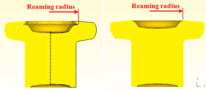
Numerical simulation of flange cold forming in one step was performed using DEFORMTM 3D. The inner hole of a proposed flange fastener was formed by extrusion and piercing. The results showed that there was a reaming and folding phenomenon during the forming process (Chang et al. [8]). The top preset depressed area of the flange can be redesigned to avoid hole edge burrs or a partial hiatus phenomenon. However, the folding and reaming cannot be eliminated if the mould geometric parameters are unsuitable. Fig. 1 displays the billet before and after a flange forming.
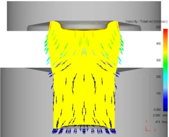
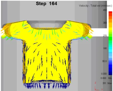
Simulation results also found that when the punch pin initially presses into the billet, the depressed area on the upper billet fits the punch pin; this shows that the initial flange forming near the punch velocity field is significantly higher than that near the die button, as shown in Fig. 2. When the punch first descended, the depressed area of the billet followed to expand the large chamfer. The billet, punch and die button surface friction coefficient caused the flow velocity of the die surface billet to be slower than that of the inside billet. Next, the velocity field of the upper flange developed an intertwined vector. Finally, the folding phenomenon occurred, as illustrated in Fig. 3. In this study, the flange forming was divided into two steps. The first step is the pre-forming of the flange shape; the second step is the final forming of flange. The preformed forming aims to find the optimal mould geometric parameters.
Fig. 2. Velocity field during initial flange forming stage (Chang et al. [8])
Fig. 3. Velocity field of folding after flange forming (Chang et al. [8])
3. Optimisation of mould geometric parameters
3.1. Pre-forming design using Taguchi orthogonal array approachThis paper used DEFORMTM 3D software combined with the Taguchi method to simulate the flange preforming process. The Taguchi method uses a special orthogonal array design to study the entire parameter space with a small number of experiments. These experimental results are subsequently transformed into an S/N ratio. The use of the S/N ratio is recommended to measure the quality characteristics that deviate from the desired values. Three types of characteristics are present in the analysis of the S/N ratio, expressed as follows:
Higher-the-better: 2 1 1 1 / H 10log n i i S N n = y = −
∑
(1)Lower-the-better: 2 1 1 / L 10log n i i S N y n = = −
∑
(2) Nominal-the-best: 2 / N 10log( ) y y S N s − = (3) wherey
is the average of the test data, n is the number of test data and y is the test data.By applying the Taguchi orthogonal array approach and the S/N ratio, this study expects to obtain the optimal parameters. It is important to avoid reaming and folding during flange preforming; the smaller the radius of the upper hole, the better the quality of the flange preforming will be. Fig. 4 shows a schematic diagram of the desired quality characteristics. Eq. 2 will be used to calculate the S/N ratio. ANOVA analysis was performed to help identify the significant factors affecting the flange performing. Using the constant-volume principle, the volume of the forged flange must be equal to the preformed one. From the results of the volume trial balance, the small diameter of the flange will increase the compressing, and lead to reaming and folding. Thus, the optimal pre-forming flange diameter is approximately 70% to 75%.
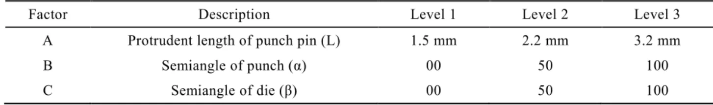
Fig. 5 illustrates the mould geometric shape, which must be controlled in order to study the folding or reaming, including the semi-angle of the punch (α), the semi-angle of the die (β), and the protrudent length of the punch pin (L). There are three levels for each controlled factor, as shown in Table 1; the factor levels of the semi-angles of the punch and die are selected as: 00, 50 and 100, respectively, the factor levels of the protrudent length of the punch are selected as: 1.5 mm, 2.2 mm and 3.2 mm.
Fig. 5. Control factors of flange performing
Table 1 Design parameters and levels for flange preforming
Factor Description Level 1 Level 2 Level 3
A Protrudent length of punch pin (L) 1.5 mm 2.2 mm 3.2 mm
B Semiangle of punch (α) 00 50 100
C Semiangle of die (β) 00 50 100
3.2. Simulated parameters of forming process
Because the elastic strain of a billet is far smaller than the plastic strain in metal cold forging, this study adopted the rigid-plastic analysis model and excluded the elastic strain of the billet. A blank of AISI-1015 material was used to simulate the cold forging process. A multi-stage former was used to forge the flange; it can be modeled as a slider-crank mechanism. The parameters of the multi-stage former, such as the eccentric amount of crankshaft, the connecting rod length, the production speed and other important parameters are shown in Table 2.
Table 2 Simulated parameters of hollow fastener with thin flange
Material of billet AISI-1015
Type of finite elements Tetrahedral mesh
Material mode of billet Plastic
Material mode of tooling Rigid body
Constant shear friction coefficient 0.08 (die), 0.12 (punch)
Forging temperature 200 C
Mechanism of former Slider-crank mechanism
Eccentricity of crankshaft 160 mm
Connecting rod length 350 mm
4. Experimental set-up
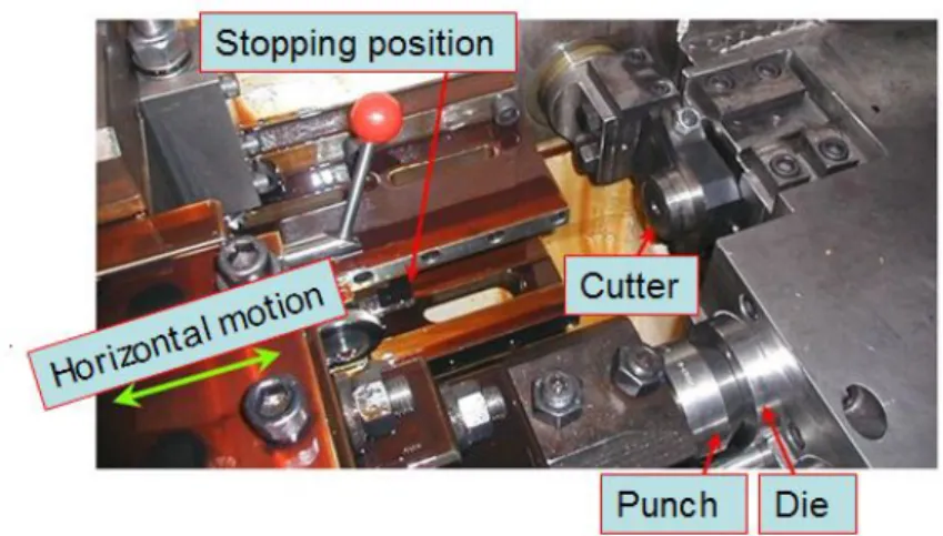
In order to perform the hollow fastener cold forging process, a multistage forging machine was used, with a slider-crank mechanism driven to the horizontal linear reciprocating motion. A wire cutter cut the desired cable length off, and it was then pushed into the mould, including the punch and die, ready for forging, as shown in Fig. 6. All dies were fixed to the front of the main block, and with the main slider punch fixed to the mould. When the main slider moved forward to the front of the dead center position, a full pass forging action was completed. The process then began to remove the main slider, and the female mould ejector mechanism would continue to push the forging blank into the jaws of each pass; these jaws were responsible for all the passes of forging embryos, which were transferred to the next pass to prepare for the next forging cycle. The main slider then moved forward again to complete a forged product. The hollow fasteners with thin flanges were made with steel wire, and manufactured by a multi-stage former with functions such as: wire straightening, auto-feeding, wire cutting, strippers, and transferring fingers to pass the forging blanks to the next step. Each mechanical reciprocation simultaneously cut billets and performed sizing, flange preforming, extrusion, piercing and flange upsetting.
Fig. 6. Schematic diagram of multi-forming horizontal forging machine
5. Results and discussion
5.1. Taguchi method experiment simulation
The following L9 (34) orthogonal array combination of factor level sequences was used to simulate and study the effect of each control factor on the reaming and folding phenomenon in flange preforming; the reaming radius and S/N ratio of each experiment were calculated using Eq. 2, as shown in Table 3. The greater the S/N ratio value, the better the quality characteristic of the experiment parameters will be.
The results showed that the fourth combination A2B1C2 S/N ratio (-14.56) is the minimum. These data also indicate the worst experimental result: with the protrudent length of the punch pin at 2.2 mm, and the semi-angle of the punch and die at 50. In contrast to this, the third combination A1B3C3 S/N ratio (-12.79) is the maximum. Therefore, the semi-angle of the punch and die (100) and the protrudent length of the punch pin (1.5 mm) are the optimal mould geometric parameters for flange preforming with the best quality characteristics.
Table 3 Simulated reaming radius and S/N ratio
Experimental No. Reaming radius Y (mm) S/N ratio (dB)
1 4.81731 -13.66 2 4.66403 -13.38 3 4.36042 -12.79 4 5.34686 -14.56 5 4.97449 -13.93 6 4.60124 -13.26 7 4.87776 -13.76 8 4.82338 -13.67 9 4.54376 -13.15
In the initial stage of flange preforming, the punch pin is first pressed into the billet, the button billet fills the die cavity, and the top node of the billet expands at an equivalent speed (Fig. 7); in the final stage of preforming (Fig. 8), the largest equivalent speed of the node occurs on the outside diameter, and the top billet remains the same.
Fig. 7. Initial velocity field of flange performing (A1B3C3)
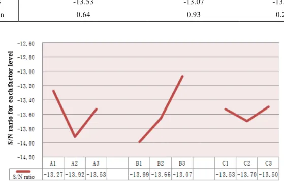
The S/N ratio response values of the simulated reaming radius of each factor were recorded, and are shown in Table 4. The results also showed that the maximum deviation between the levels of the semi-angle of the punch is B = 0.93, of the protrudent length of the punch pin it is A = 0.64, and of the semi-angle of the die it is C = 0.2. Fig. 9 shows that the semi-angle of the punch is the most important mould geometric parameter affecting flange preforming.
Table 4 S/N ratio response table of simulated reaming radius
Control factors The protrudent length of punch pin (A) The semi-angle of punch (B) The semi-angle of die (C)
Level 1 -13.27 -13.99 -13.53
Level 2 -13.92 -13.66 -13.70
Level 3 -13.53 -13.07 -13.50
Max-Min 0.64 0.93 0.20
Fig. 9. S/N ratio response graph of simulated reaming radius
Using ANOVA, the results in Table 5 indicate that a 60.3% contribution of the semi-angle of the punch (factor B) is the most significant factor affecting the flange performing process.
Table 5 ANOVA of simulated reaming radius
Control factors squares Sum of Degrees of freedom square Mean of squares Pure sum F-ratio Contribution (%) Percent
A 0.632 2 0.3161 0.5673 9.76 27.1% B 1.327 2 0.6636 1.2624 20.49 60.3% C 0.686 2 0.0343 0.0039 1.06 0.2% Error 0.648 2 Residual 0.648 2 0.0324 0.259 1.00 12.4% Total 2.093 8 100%
5.2. Examination of flange preforming folding
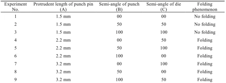
Table 6 shows that if the semi-angle for a punch or a die is 00, 50 or 100, with a punch pin protrudent length of 1.5 mm, then there is no folding phenomenon. However, if the punch pin protrudent length is 2.2 mm or 3.2 mm, then folding occurs. As a result, the protrudent length of the punch pin is related to the folding phenomenon. Figure 10 describes the distance from the billet folding position to the punch surface. The folding position of the punch pin protruding length (PL) of 3.2 mm is much lower than that of 2.2 mm with the same punch angle (PA). The results also showed that if the semi-angle of the punch is increased, then the folding position sharply decreases. Furthermore, because the semi-angle of the punch significantly affects flange preforming, the smaller the semi-angle of the punch, the bigger the folding reaming radius with the same punch pin protrudent length will be, as shown in Fig. 11.
Table 6 The folding records of simulated experiments Experiment
No. Protrudent length of punch pin (A) Semi-angle of punch (B) Semi-angle of die (C) phenomenon Folding
1 1.5 mm 00 00 No folding 2 1.5 mm 50 50 No folding 3 1.5 mm 100 100 No folding 4 2.2 mm 00 50 Folding 5 2.2 mm 50 100 Folding 6 2.2 mm 100 00 Folding 7 3.2 mm 00 100 Folding 8 3.2 mm 50 00 Folding 9 3.2 mm 100 50 Folding
Fig. 11. Comparative folding reaming radius
It can be concluded that if the punch pin protruding length is 1.5 mm, the forging blank will not experience folding; however, if the length is 2.2 mm, folding will occur. Therefore, it is necessary to research the length in the range from 1.5 to 2.2 mm. This study also conducted simulations with the optimal semi-angle for the punch and the die button at 100 and the protrudent length of the punch pin at 1.8 mm. At the end of the preforming stage, the equivalent velocity vector of the nodes, which nears top sink billet, is staggered (Fig. 12).
Fig. 12. Final preforming stage 5.3. Comparison of simulation and experiment results
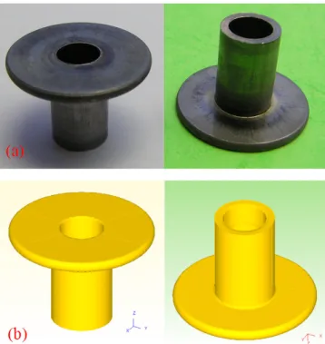
This section examines the folding defect occurring in the upper billet. Comparing the simulated forging blank (Fig. 13a) with the actual one (Fig. 13b), it can be seen that the folding position and the shape of the top inner hole
of the flange are identical. This proves that the FE simulation was able to effectively predict the folding defect which occurs during the forming process. Comparing the final actual forging blank (Fig. 14a) with the simulated result (Fig. 14b), it can be seen that they are identical.
Fig. 13. Comparison of folding defects between simulation and actual forging:
Fig. 14. Comparison of forging blanks between simulation and real trial
6. Conclusions
This study presented a combination of DEFORMTM 3D and the Taguchi method to obtain optimal mould geometric parameters for the cold forging of hollow fasteners with thin flanges.
The results showed that folding occurs during the performing process. The optimal mould geometric parameters obtained by the FEM and Taguchi method are a 100 semi-angle for the punch and the die, and a punch pin protrudent length of 1.5 mm. ANOVA results showed that the most significant factor affecting flange
preforming is the semi-angle of the punch. Another important parameter affecting flange cold preforming is the protrudent length of the punch pin. If the protruding length is longer, folding will occur more easily, and the folding position will be farther from the upper flange surface. With the protrudent length of the punch pin kept the same, the folding position decreases, the angle of the punch is increased, and the folding reaming radius becomes relatively smaller. The FE analysis results were always in good agreement with the experimental results. This proves that the proposed approach can accurately predict the metal forming process forming defects in order to reduce repetitive trials and the time required to modify tools.
Reference
[1] Hu, X.L. and Wang, Z.R., “Numerical Simulation and Experimental Study on the Multi-Step Upsetting of a Thick and Wide Flange on the End of a Pipe”, Journal of Materials Processing Technology, Vol. 151, pp. 321-327, 2004.
[2] Lin, H. S., Lee, C. Y., and Wu, C. H., “Hole Flanging with Cold Extrusion on Sheet Metals by FE Simulation”, International Journal of Machine Tools & Manufacture, Vol. 47, pp. 168-174, 2007.
[3] Kacem, A., Krichen, A., and Manach, P. Y., “Occurrence and Effect of Ironing in the Hole-Flanging Process”, Journal of Materials Processing Technology, Vol. 211, pp. 1606-1613, 2011.
[4] Farhoumand, A. and Ebrahimi R., “Analysis of Forward–Backward-Radial Extrusion Process”, Materials and Design, Vol. 30, pp. 2152-2157, 2009.
[5] Chen, D.C., You, C.S., Nian, F.L., and Guo, M.W., “Using the Taguchi Method and Finite Element Method to Analyze a Robust New Design for Titanium Alloy Prick Hole Extrusion”, Procedia Engineering, Vol.10, pp. 82-87, 2011.
[6] Cao, C. H., Hua, L., and Liu, S. L., “Flange forming with combined blanking and extrusion
process on sheet metals by FEM and experiments”, Int J Adv Manuf Technol, Vol. 45, pp. 234-244, 2009.
[7] Cho, H.Y., Min, G.S., Jo, C.Y, and Kim, M.H., “Process design of the cold forging of a billet by forward and backward extrusion”, Journal of Materials Processing Technology, Vol.135, pp. 375-381, 2003.
[8] Chang, T.P., Huang, S.C., Huang, T.F., and Dao, T.P., “Analysis of Cold Preforming Process for Hollow Fasteners with Thin Flange’, Applied Mechanics and Materials, Vol. 418, pp 246-249, 2013
![Fig. 1. The folding phenomenon after flange forming (Chang et al. [8])](https://thumb-ap.123doks.com/thumbv2/9libinfo/8826084.233952/2.892.235.659.902.1149/fig-the-folding-phenomenon-after-flange-forming-chang.webp)
![Fig. 2. Velocity field during initial flange forming stage (Chang et al. [8])](https://thumb-ap.123doks.com/thumbv2/9libinfo/8826084.233952/3.892.224.673.160.432/fig-velocity-field-initial-flange-forming-stage-chang.webp)