The design concept and construction
planning of intake pipe in Zengwen reservoir
sediment sluicing tunnel
Shih-Hsien Chang1, Shang-Yao Lien2, Chin-Cheng Yeh3, Ping-Tsung Chung4, Cheng-Yang Yen5
Abstract
The Zengwen Reservoir is the largest reservoir in Taiwan and also the most significant water resource in Chia-nan plain area. However, its capability keeps decreasing by the increasing of sediment deposition since operating in 1974. Due to the lack of sediment sluicing facilities, a new sediment bypass tunnel is planned on the left side of the dam base to extend the service life of the reservoir.
The reservoir has a full water level of an elevation of 230m and the sediment level in front the dam is about an elevation of 170m. Because the water depth in front the dam is as deep as 60 meters, so the construction of the tunnel intake is very difficult. In order to make the intake to reach the bottom of the reservoir without to install a huge cofferdam, we plan to construction a huge trunk pipe to extend the intake from the elevation of 190m to the elevation of 170m, therefore, the intake can reduce the underwater depth from 60 meters to 40 meters.
The operation concept of intake trunk pipe is to open the control gate when the reservoir water level is higher than control gate, at this time, the turbid in the bottom of reservoir at an elevation of 170m will flow upward through trunk pipe that caused by pressure and flush out from the control gate at the elevation of 190m. For the reason to discharge all the materials at the bottom of the reservoir, including silt and sinking wood, the trunk pipe must be of sufficient size, so the designers decided to build a 10m diameter steel pipe.
In order to install this huge steel pipe, the constructors need to excavate the tunnel and rock slope underwater. For the pipe weighing up to 1,500 tons, how to transport and accurately connect to the tunnel is also another major challenge.
Designers and constructors work together to find solutions, including the manufacture and transportation of trunk pipe, installed the trunk pipe accurately with the help of divers, risk of water leakage when excavating tunnels, mass rock excavation of intake slope underwater within the required time limit. All the challenges are solved one by one, so the project has been successfully completed.
Keywords: Zengwen reservoir, desiltation of reservoir, intake trunk pipe, tunnel excavation
1 Overview of engineering facilities
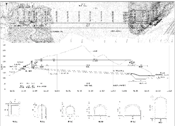
The water intake of the anti-silting tunnel project is located at the left part of the dam. It is expected that the maximum flood discharge of 1,075cms is achieved when the maximum flood level of the reservoir is EL.232.5m. The length of the whole project is about 1,235.2 meters. The main concerns of the project (Abb. 1) are described as follows:
Abb. 1: Picture of Sediment sluicing tunnel engineering layout
A. Intake trunk pipe section (0K-143.89 ~ 0K-089.35): The structure consists of steel pipes which are laid downwards along the slope. The elevation of the structure is EL.195.0m (measured to the center of pipes). The inner diameter of the steel pipe is 10.0 meters. The pipe length is about 60 meters.
B. Intake tunnel section (0K-089.35 ~ 0K-031.15) This section is connected to the trunk pipe and lock chamber, with a total length of 58.2 meters.
C. Shaft gate section (0K-031.15 ~ 0K+000.00):This section has a total length of 31.15 meters. The underground lock chamber is equipped with a vertical lift gate for emergency shut-off purpose and a curved gate for operational purpose.
D. Tunnel section (0K+000.00 ~ 0K+862.82):The length of this section is 862.82 meters. From the rear of the underground lock chamber, the rectangular section gradually becomes outer three-hearted tunnel section. The inner diameter is φ9.00 meters.
E1. Dissipator pool (0K+862.82 ~ Sta.0K+992.12):In order to effectively dissipate energy, dissipator pool is set up at the end of the tunnel. The maximum net height and width is 41.69 meters and 18.0 meters, respectively. The total length of the pool is 90.0 meters.
E2. Outlet tunnel (0K+992.12 ~1K+073.93):Considering the tunnel structural safety, the dissipator pool chamber original net width of 18 meters is divided into two tunnels (which consists of north and south part with the hole width of 10 meters).
E3. Outlet works (1K+067.12 ~1K+091.32):The outlet works is connected to the north and south tunnel. Then, it gradually expands to 65.83 meters long overflow weir.
2 Important project issues and countermeasures
2.1 Water retention planning and design for water intake construction
The construction is performed under the condition of operating dam. For that reason, it is impossible to influence the water supply to fit the construction needs. The construction must be performed without venting the dam or lowering the water level. Hence, the water retention for intake construction is an important project issue.
Therefore, during the planning and basic design stage (2012), the concept of different construction methods including rock plug blasting and cofferdam construction has been evaluated under the conditions of the water level change at the intake end.
The advantage of using rock plug blasting is that the anti-silting tunnel function focuses on the bottom hole discharging. If the tunnel can be directly excavated at the bottom of the reservoir, this construction method is the most convenient. However, after the geological survey, it is doubted that rock plug blasting method is suitable due to the geological softness and base rock condition.
On the other hand, there is a harsh consideration about the size of the cofferdam due to the water level of the full reservoir (which is more than 50 meters deep) if the traditional construction cofferdam method is adopted. Hence, it is necessary to consider the appropriate way to reduce the depth of the cofferdam in order to fulfill the current project original idea about trunk steel pipes.
The design of the trunk steel pipe is intended to increase the intake tunnel entrance elevation. The pipe is extended downward to drain the sediment at the bottom of the reservoir. At present, the design elevation of pipe bottom is EL.190.0m extends downwards to the elevation of intake pipe bottom at EL.170.0m. When the pipe is fully immersed by the stored water, the water pressure can be used to induce the water on the bottom to flow upwards.
Although the trunk pipe can reduce the size of the cofferdam, the top opening of the cofferdam may still be affected by abnormal flooding and there is doubt about
overflowing. Therefore, after the design and construction discussion of the turnkey team, the trunk pipe water diversion method is refined to prevent it from being affected by the rise and fall water level of the reservoir.
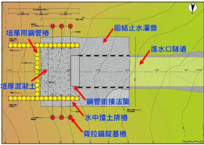
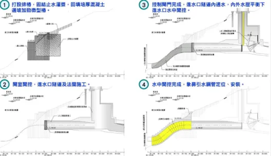
The main idea is to use the low water period during the previous year or two. By making use of the reservoir low water period, side slope reinforcement works such as retaining piles, consolidation water stop grouting and seaming method are performed beforehand. At the later stage of the project, when the intake tunnel is excavated and demolished to the predetermined part, the site of tunnel excavation is already within the scope of the above-mentioned slope reinforcement and protection area. Therefore, it greatly enhances the construction safety.
After the tunnel excavation is completed, the following items are installed sequentially from upstream end to the downstream as follows: the steel pipe with joint flange, tunnel lining, underground lock chamber structure and hydraulic mechanical gate. After that, the operation trial is performed.
Hence, the intake tunnel, the control gate and the lock chamber have been completed when the tunnel holing-through section is excavated. The intake tunnel excavation works will not be affected by the water level at that time and there is no risk of the tunnel collapse during the excavation.
Abb. 2: Picture of Engineering layout
Based on the above understanding of the planned construction method of the intake, it is summarized as follows:
A. Adjusting the construction process, the shaft gate chamber at the downstream side of the tunnel section is not penetrated during the excavation of the tunnel and intake section. After confirming the structural alignment of the intake section and the control gate are completed and operated without any flaws, the downstream tunnel section can be penetrated. It is performed to avoid the construction convulsion which may lead to the water outbreak from the reservoir.
B. During the low water level period from March to May every year, pre-consolidation grouting from the surface slope to the surrounding rock section of the inflow tunnel section are performed to strengthen the softened base rock due to water immersion and the shear zone of NWF-3 fault.
C. The water intake tunnel junction is arranged in an H-shaped layout. The longitudinal piles row on both sides are used as the support of the excavation surface for trunk pipes installation. In addition, these longitudinal piles also extend to a certain range towards the mountain and overlap with the water intake tunnel. It is to ensure the affected area is between the rows of piles on both sides if there is a convulsion during the tunnel excavation.
D. In addition to the piles row arranged in H-shaped layout, the horizontal piles row facing the water are designed with steel pipe piles. During the excavation, the steel pipe piles facing the water will ensure that if there is a convulsion in the tunnel excavation, the construction process facing the reservoir storage area will still have the first protection from the steel pipes.
E. Due to the steep terrain of the slope, the H-shaped layout piles row are covered with low-strength concrete on the mountain side to ensure the site above tunnel excavation has coverage depth of at least one times tunnel depth.
F. After the excavation in water and the removal of external force from the steel pipe piles, the vertical excavation is performed above the intake tunnel which is almost 10 meters. In order to ensure the stability of this excavation surface, the micro-pile will be implanted through the grouting hole. The stability of the slope will be achieved through.
G. After the installation of the trunk pipes and the flange of the inlet tunnel section, the cast in water concrete and box type gabions are used to achieve permanent slope stability.
2.2 Design and installation concept of trunk steel pipes
In order to achieve the purpose of diverting the bottom layer of water, it is necessary to install a huge steel pipe which enables all debris from the coming flood pass through or penetrate deep enough to drain the silt. The main difficulties and important issues regarding the manufacture and installation of this huge steel pipe are as follows:
A. The diameter of the trunk steel pipe is up to 10.0 meters, which is classified as a large diameter steel pipe. Based on the general steel pipe design principle, the pipe wall thickness is at least 100mm. This will lead to manufacture and processing difficulty. B. After the production of the pipes is completed, the weight exceeds 1,000 tons. The construction challenge is on how to effectively transport and install the pipes to the predetermined position without sinking into the water.
In order to solve the above problems, the JV team member- Kuo Toong International Co., Ltd. (hereinafter referred to as Kuo Toong Company) has many years of engineering experience to overcome the above key problems with special structural design which are described as follows:
A. The trunk steel pipe is configured as a double-layer type pipes consisting of inner and outer layers, thereby amplifying the value of the inertia distance I of the steel pipe structure to reduce the thickness of the steel plate, so that the weight of the steel pipe is reduced, but the bending moment resistance is greatly improved (Abb. 4).
B. In the double-layer type pipes, the inner and outer steel plates must be joined by a stiffening plate to achieve the web effect. Below the separation of the longitudinal and transverse webs, a closed compartment of different sizes is formed in the double-layer pipes. When trunk steel pipe works is performed in water, the closed compartment will have a similar function to a submarine, providing buoyancy resistance to the weight of the huge steel pipe.
C. The huge trunk steel pipes cannot be transported by land transportation to the intake end for installation. Therefore, the reservoir must be used as the waterway transportation. Therefore, the double-layer steel pipe compartment is suitable for providing the buoyancy required for underwater operations.
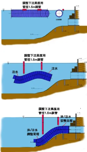
D. After the steel pipe is transported to the intake site, the angle and depth of the steel pipe must be adjusted in the water. This process will use the empty space in the double pipe as buoyancy and inject different water volumes into different compartments to control the angle and depth of the steel pipe structure in the water, assisted by anchoring the cable on the shore and the assisting steel pipe on both sides to achieve the purpose of adjusting the position of the steel pipe at the intake end, meets the requirement of steel pipes construction and installation (Abb. 5)
This trunk pipes method is the world's first construction method. Based on the originality of this method and the irreversibility of the specific risks in construction, the design and review of this work method involves experts from various fields to participate, including the assistance and discussion of experts and scholars in the field of shipbuilding. In addition, after the design is completed, the model is manufactured in an equal proportion of 1/20 ratio. Then, verification is performed for the actual entering water process, transporting process, position adjustment, sinking installation and other processes.
Abb. 4: Picture of Standard section of elephant trunk water pipe
Abb. 5: Picture of Installer schematic
3 Conclusions
After the catastrophic siltation of the Zengwen Reservoir caused by the Morakot typhoon, the Ministry of Economic Affairs of Southern District Water Resources Bureau actively performed the feasibility assessment and planning of the hydraulic sand removal plan. And the basic design was completed by United Geotech Inc. and G.T. International in 2012. It was implemented in the「Zengwen Nanhua Wushantou Reservoir Management and Stabilization of the Southern Region Water Supply Project」, and in 2013 by BES Engineering Corporation, Kuo Toong International Co., Ltd. and Liming Engineering Consultant Co., Ltd. formed a turnkey team to sign and execute the project. Thanks to all
the advanced engineering care and guidance for this project, the construction team will continue to work hard and improve, so that the project will be completed as scheduled in order to achieve the project goal of extending the service life of the reservoir.
Authors (Text style: Authors Address)
1. Section Chief, Southern Region Water Resources Office, Water Resources Agency 2. Director, Southern Region Water Resources Office, Water Resources Agency 3. General manager, Kuo-Toong International Co., Ltd
4. Engineer, Liming Engineering Consultants Co., Ltd (corresponding Author) 5. Manager, Liming Engineering Consultants Co., Ltd
3F No. 137, Dadun 17th St, Nantun District, Taichung City, Taiwan, 408 Email: cptthor63@gmail.com