國
立
交
通
大
學
多媒體工程研究所
碩
士
論
文
利用超音波訊號分析與模糊控制技術
作室內自動車學習與導航之研究
A Study on Automatic Learning and Guidance for Indoor
Autonomous Vehicle Navigation by Ultrasonic Signal Analysis and
Fuzzy Control Techniques
研 究 生:陳梅芬
指導教授:蔡文祥 教授
利用超音波訊號分析與模糊控制技術作室內自動車學習與導航之研究
A Study on Automatic Learning and Guidance for Indoor Autonomous Vehicle
Navigation by Ultrasonic Signal Analysis and Fuzzy Control Techniques
研 究 生:陳梅芬 Student:Mei-Fen Chen
指導教授:蔡文祥 Advisor:Wen-Hsiang Tsai
國 立 交 通 大 學
多 媒 體 工 程 研 究 所
碩 士 論 文
A ThesisSubmitted to Institute of MultimediaEngineering
College of Computer Science National Chiao Tung University in partial Fulfillment of the Requirements
for the Degree of Master
in
Computer Science June 2009
Hsinchu, Taiwan, Republic of China
利用超音波訊號分析與模糊控制技術作室內自動車學習與導航之研究
研究生:陳梅芬 指導教授:蔡文祥 博士 國立交通大學多媒體工程研究所 摘 要 本研究提出了一套智慧型自動車系統,利用超音波訊號分析,讓自動車能具有跟隨 使用者行走,並同時學習路徑、與人互動、做路徑分析,以及進行智慧型導航等功能。 我們利用一台具有超音波感測器的自動車作為實驗平台,使其航行於室內走廊環境中。 針對跟隨人物,我們提出了一個利用超音波和模糊控制來讓自動車動態跟隨使用者的方 法。另外,為了能讓使用者與自動車互動以下達控制指令,我們提出了一個分析使用者 的行為以取得控制指令的方法,先以超音波偵測使用者的行走軌跡和特定姿勢,再利用 投票的方式來決定使用者對自動車所下達的控制指令。在學習完路徑後,我們提出了一 個自動分析路徑的方法,能經由學習過的路徑分析出導航時所需的轉彎參數等資訊。接 著,我們提出了一個利用超音波和模糊控制進行導航的方法,在導航時,利用牆壁資訊 作為環境特徵,並使用所設計的模糊控制器結合路徑資訊和超音波訊號,來調整自動車 的方向。我們還提出了一個能在導航時利用轉彎參數和超音波以判斷是否抵達轉彎點的 方法。最後我們以成功的學習和導航實驗證明了本系統的完整性與可行性。A Study on Automatic Learning and Guidance for Indoor Autonomous
Vehicle Navigation by Ultrasonic Signal Analysis and Fuzzy Control
Techniques
Student: Mei-Fen Chen Advisor: Prof. Wen-Hsiang Tsai, Ph. D.
Institute of MultimediaEngineering, College of Computer Science
National Chiao Tung University
ABSTRACT
An intelligent autonomous vehicle system for learning and vehicle guidance in indoor environments is proposed. The system has several capabilities: learning paths by person following, interaction with humans, path analysis, and navigation as a guide. An autonomous vehicle equipped with ultrasonic sensors is used as a test bed. First, a method for person following in an environment is proposed, which has two fuzzy controllers for following a person dynamically. The fuzzy controllers adjust the vehicle’s direction and speed. Furthermore, to interact with humans, a technique for analyzing human behaviors is proposed, which analyzes a person’s walking trajectory by ultrasonic signals and uses a voting technique to obtain human commands implied by the walking postures. After learning, a method for path analysis is proposed, which analyzes the learned path data to estimate certain turning parameters for navigation. In addition, a method for vehicle navigation guidance by the use of the ultrasonic signal sequence and a fuzzy controller is proposed. The main environment feature used for navigation is wall. The fuzzy controller combines some information obtained from path analysis with ultrasonic signals to adjust the vehicle’s navigation direction. A
vehicle arrives at a turning point or not, using learned data and ultrasonic signals as well. Good experimental results show the flexibility and feasibility of the proposed system for the applications of person following, path analysis, and people guiding in indoor environments.
ACKNOWLEDGEMENTS
The author is in hearty appreciation of the continuous guidance, discussions, support, and encouragement received from her advisor, Dr. Wen-Hsiang Tsai, not only in the development of this thesis, but also in every aspect of her personal growth.
Thanks are due to Mr. Chih-Jen Wu, Mr. Che-Wei Lee, Mr. Guo-Feng Yang, Mr. Jian-Yuan Wang, Miss Chin-Ting Yang, Mr. Yi-Chen Lai, Miss Chiao-Chun Huang, Mr. Chun-Pei Chang, and Miss Shu-Hung Hung for their valuable discussions, suggestions, and encouragement. Appreciation is also given to the colleagues of the Computer Vision Laboratory in the Institute of Computer Science and Engineering at National Chiao Tung University for their suggestions and help during her thesis study.
Finally, The author also extend her profound thanks to her family for their lasting love, care, and encouragement. The author dedicates this dissertation to her beloved parents.
CONTENTS
ABSTRACT (in Chinese) ...i
ABSTRACT (in English)...ii
ACKNOWLEDGEMENTS ...iv
CONTENTS ... v
LIST OF FIGURES ...vii
LIST OF TABLES ...ix
Chapter 1
Introduction... 1
1.1 Motivation...1
1.2 Survey of Related Studies...2
1.3 Overview of Proposed Approach...4
1.4 Contributions...6
1.5 Thesis Organization ...7
Chapter 2
System Configuration and Navigation Principles ... 8
2.1 Introduction...8
2.2 System Configuration ...9
2.2.1 Hardware configuration...9
2.2.2 Software configuration ...10
2.3 Idea of Proposed Person Following and Learning Method ...10
2.4 Idea of Proposed Path Analyzing and Guiding Method...13
2.5 Idea of Proposed Vehicle Navigation Method ...15
Chapter 3
Human Following by Fuzzy Logic Control for Path Learning
... 17
3.1 Introduction...17
3.2 Learning of Path Data ...17
3.3 Review of Design Principle of Fuzzy Logic Control System...21
3.3.1 Fuzzy sets and membership functions...21
3.3.2 Basic architecture of a fuzzy logic controller...23
3.4 Proposed Fuzzy Logic Control Techniques for Human Following ...24
3.4.1 Proposed method for controlling vehicle direction ...24
3.4.2 Proposed method for controlling vehicle speed ...28
3.5 Vehicle Stopping, Turning, and Restarting Techniques ...33
3.5.1 Stopping technique ...33
3.5.2 Turning technique...33
3.6 Algorithm of Proposed Method for Path Learning ...36
Chapter 4
Path Analysis Using Ultrasonic Signals ... 38
4.1 Introduction...38
4.2 Path Data for Navigation ...38
4.3 Techniques for Path Analysis...41
4.3.1 Turning ...42
4.3.2 Computing distances between walls...46
4.3.3 Computing intolerable distance to obstacles in front of the vehicle ...50
4.3.4 Stopping...52
4.3.5 Introducing objects or places as a guide...53
4.4 Algorithm of Proposed Method for Path Analysis...54
Chapter 5 ALV Navigation by Ultrasonic Signal Sequence and Fuzzy
Logic Control... 55
5.1 Introduction...55
5.2 Proposed Fuzzy Logic Control Techniques for Navigation...57
5.2.1 Proposed method for controlling vehicle direction ...57
5.2.2 Proposed fuzzy controller...59
5.3 Vehicle Turning Technique ...67
5.4 Algorithm of Proposed Method for ALV Navigation ...71
Chapter 6
Experiment Results and Discussions... 73
6.1 Experimental Results ...73
6.2 Discussions ...86
Chapter 7
Conclusions and Suggestions for Future Works... 89
7.1 Conclusions...89
7.2 Suggestions for Future Works...91
LIST OF FIGURES
Figure 1.1 Flowcharts of proposed systems. ...5
Figure 2.1 Equipment of vehicle system used in this study...9
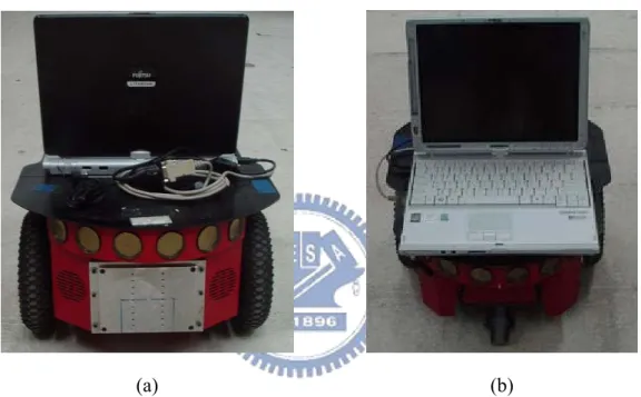
Figure 2.2 The vehicle Pioneer 3 with a notebook used in this study. (a) A front view of the vehicle. (b) A back view of the vehicle. ... 11
Figure 2.3 An illustration of proposed process of automatic learning by person following and fuzzy logic control techniques...12
Figure 2.4 Illustration of proposed path analysis process. ...14
Figure 2.5 Illustration of proposed navigation process. ...16
Figure 3.1 Illustration of proposed learning procedure. ...18
Figure 3.2 Illustration of sonar arrays ...20
Figure 3.3 An example of characteristic functions of a classical set A and a fuzzy set A%...22
Figure 3.4 Basic architecture of a fuzzy logic controller...23
Figure 3.5 Three kinds of relative positions of the vehicle and a person. The blue circle represents the person and the arrows represent the signals of the ultrasonic sensors equipped in front of the vehicle. (a) The vehicle moves on a straight path. (b) The vehicle moves on a curve path. (c) The vehicle moves on a curve path. ...25
Figure 3.6 The membership functions of the three fuzzy terms, NE, MI, and FA. ...26
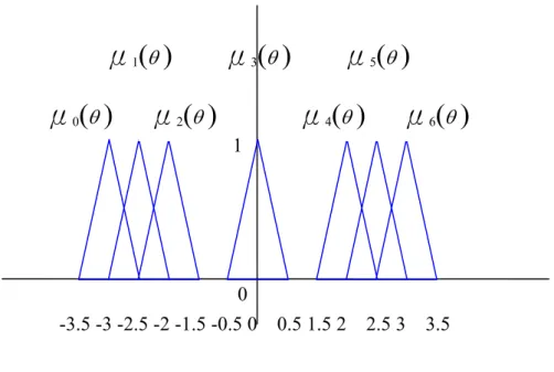
Figure 3.7 The membership functions of the seven fuzzy terms of the controlled linguistic variable ANGLE...28
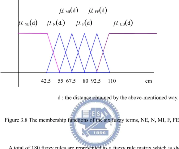
Figure 3.8 The membership functions of the six fuzzy terms, NE, N, MI, F, FE, and UB. ...30
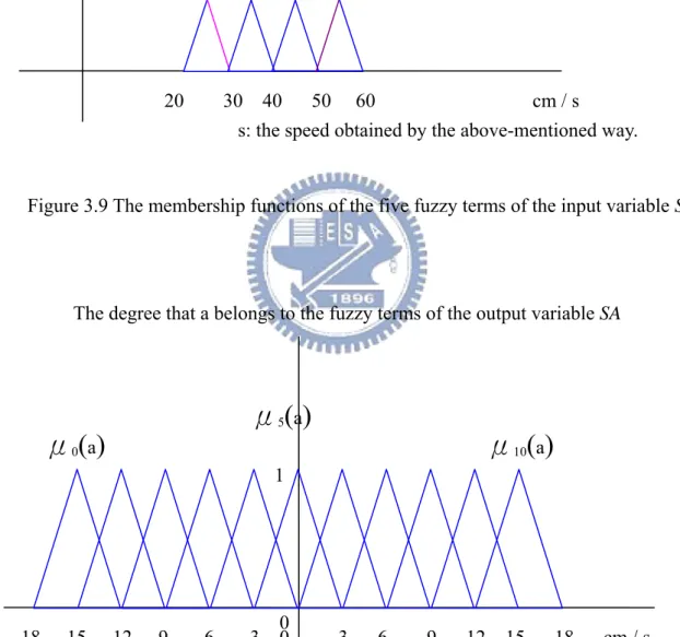
Figure 3.9 The membership functions of the five fuzzy terms of the input variable SV. ...31
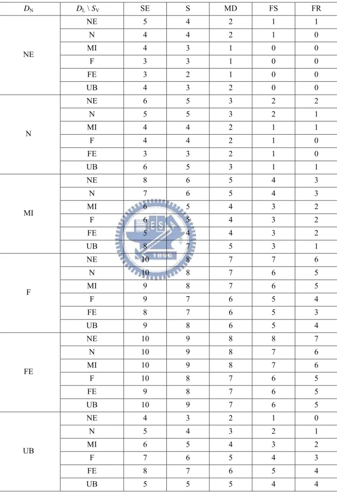
Figure 3.10 The membership functions of the eleven fuzzy terms of the output variable SA..31
Figure 4.1 Illustration of proposed procedure of path analysis. ...39
Figure 4.2 Illustration of when to turn...41
Figure 4.3 An example to explain the idea of turning. ...44
Figure 5.1 Illustration of proposed navigation procedure. ...56
Figure 5.2 The membership functions of the five fuzzy terms, NE, N, MI, F, and FE, where d is the distance obtained by ultrasonic sensor No. 0 or 7, and w is the distance between walls...59
Figure 5.3 An illustration of DUS, the distance between ultrasonic sensors Nos. 0 and 15. ...61
Figure 5.4 Membership functions of the estimated relative angle, VEL or VER, and represented as very left (D1), left (D2), straight (D3), right (D4), or very right (D5)...62
Figure 5.5 Membership functions of credibility CRL and CRR...63
Figure 5.7 The membership functions of the seven fuzzy terms of the output linguistic variable
ANGLE where θ is the angle which the vehicle needs to turn...67
Figure 6.1 An interface of the experiment with yellow box shows a draft of environment map. ...73 Figure 6.2 An experiment result of detecting a person. (a) The person stands in front of the
vehicle. (b) The vehicle detects the person and starts to follow the person. ...74 Figure 6.3 An experiment result of following a person. (a) The vehicle follows the person. (b)
The vehicle’s direction is with some deviation and it detects the person. (c) The vehicle adjusts its direction to keep following the person...75 Figure 6.4 An experiment result of stopping. (a) The vehicle follows the person. (b) If the ...76 Figure 6.5 An experiment result of turning. (a) The vehicle analyzes the person’s command. (b)
The vehicle turns according to the person’s command turning. (c) The vehicle restarts to follow the person. ...77 Figure 6.6 An experiment result of a learned path. The black circles are spots specified by the
coordinates obtained from the odometer and the red lines are the distances obtained from ultrasonic sensors...78 Figure 6.7 An illustration of the path of following a person in an experiment. ...78 Figure 6.8 An interface of the experiment...79 Figure 6.9 An interface of the experiment with yellow box showing a draft of environment map.
...80 Figure 6.10 An illustration of the path of navigation in an experiment...81 Figure 6.11 An experimental result of navigation in an indoor environment. (a) The vehicle
navigates on the path. (b) The navigation map with red circle indicating the current position. ...82 Figure 6.12 An experiment result of a navigation path. The black circles are spots specified by
coordinates obtained from the odometer and the red lines are the walls plotted according to the distances obtained from the ultrasonic sensors...87
LIST OF TABLES
Table 3.1 All kinds of the learned information...19
Table 3.2 The fuzzy rule matrix for controlling the vehicle direction...27
Table 3.3 The fuzzy terms of the output variable ANGLE...27
Table 3.4 The fuzzy rule matrix for controlling the vehicle’s speed. ...32
Table 3.5 The fuzzy terms of the output variable SA. ...33
Table 3.6 List of the ultrasonic sensors and commands represented by them, respectively...35
Table 4.1 All kinds of the information of the path data for navigation. ...42
Table 5.1 The fuzzy rule matrix for controlling the vehicle direction...68
Table 5.2 The fuzzy terms of the output variable ANGLE...69
Chapter 1
Introduction
1.1
Motivation
In recent years, autonomous vehicles have more and more applications. It is not only convenient but also effective to use autonomous vehicles in many human works. For example, they can used to patrol in buildings, monitor important objects, and become security guards.
When we visit an office in a building, we usually desire some guidance to introduce the environment to us. The most common way is to set up a sign with some explanation. Sometimes, a staff will act as a guide. Furthermore, in an exhibition, visitors can reserve a guide to introduce the exhibition, but this may not be convenient. This problem may be solved if we use an autonomous vehicle to act as a guidance.
In order to do the above-mentioned tasks, an autonomous vehicle should have the abilities to navigate in indoor environments and guide visitors. The work to build an autonomous vehicle to have such abilities can be separated into two parts: the first is that the vehicle has to learn a guiding path, and the second is that it should be able to navigate and guide visitors.
In an office or an exhibition, the decoration may be changed after a period. It will be very inconvenient if a vehicle has to learn new environments in a repetitive way. This problem can be solved if the vehicle can follow a person and learn an indoor environment in the mean time. Furthermore, it may not be smart for a vehicle to navigate by following a learned trajectory step by step in a precise way, because the trajectory might be rough and curvilinear.
sequences of objects which it has to introduce without hitting walls in a narrow environment. In order to achieve the above goals, we will use an autonomous vehicle equipped with ultrasonic sensors to learn a corridor and keep it navigating in the learned paths safely. In addition, we will implement the above ideas by fuzzy logic control techniques because such techniques can be utilized to control a vehicle more smoothly in general.
In summary, our research goal of this study is to design an intelligent autonomous vehicle system with the following capabilities:
1. learning corridors environments automatically by following a person; 2. controlling the vehicle by fuzzy logic control techniques;
3. analyzing learned information to plan appropriate paths to navigate; and 4. navigating automatically in corridors and guiding people.
1.2
Survey of Related Studies
To learn a guidance map, it is desired that an autonomous vehicle have the abilities of following a person and recording a map in the mean time. To achieve the mission of person following in indoor environments, cameras may be used as sensors. Wang and Tsai [1] proposed a method for person following, which uses an elliptic skin model to detect human faces by color and shape features in images. Tsai and Tsai [2] proposed a method for the same purpose in environments where the luminance is not uniform.
In addition, Ku and Tsai [3] proposed a sequential pattern recognition method to decide the location of a person with respect to a mobile robot and to detect a rectangular shape attached on the back of the person to achieve smooth person following. Kwolek [4] proposed a method of visual head tracking and person following by a mobile robot. They used laser readings to determine the position of the vehicle and a particle filtering technique to track the
human head. Chueh, Yeung, Lei, and Joshi [5] proposed a method to integrate information provided by the behavioral cues of the leader to enhance the reliability and the performance of following. They utilized a Kalman filter to estimate the predicted position of the leader as the robot moves, and then direct the following robot to the predicted position. Takemura, Ito, and Mizoguchi [6] proposed a method to detect a target person according to the colors of the followed person’s clothes and the H-S Histogram of the color based on the HIS color model.
For applications of fuzzy logic control techniques, some studies used them on person following and some used them for navigation control of mobile robots. Tarokh and Ferrari [7] proposed a method for a mobile robot to follow a person using a fuzzy controller. They utilized image colors, shape characteristics, and a region growing technique in a person identification process, and used image features such as the mass, the center of mass, and their rates of changes as inputs to the fuzzy controller. Peri and Simon [8] proposed a fuzzy control method to control an autonomous wall-following robot equipped with ultrasonic sensors. The robot can navigate along a predefined path. Xin, et al. [9] proposed a fuzzy control method for an unmanned exploration vehicle equipped with ultrasonic sensors. They used a fuzzy logic algorithm to fuse the vehicle’s behaviors and self-tuning membership functions to control the vehicle. Datta, Banerji, and Mukherjee [10] proposed a method for mobile robot localization using laser-based maps. They also proposed a fuzzy controller for obstacle avoidance.
Furthermore, some studies used fuzzy logic control techniques to control a mobile robot in unknown environments. Islam, et al. [11] proposed a fuzzy control algorithm to guide a mobile robot to navigate in an unstructured environment and avoid any encountered obstacle without human intervention. Tan and Yang [12] proposed a fuzzy-inference controller for navigation control of a mobile robot in dynamic environments. They also described a good idea for avoiding moving obstacles: like a person driving a car at an intersection and facing another moving car, when a mobile robot faces a moving obstacle, it can stop instead of
be able to find an even shorter path to the target.
Meng and Liu [13] proposed a behavior-based navigation strategy for autonomous robots. Li and Zong [14] proposed a hierarchical fuzzy controller to improve the problem that a designed fuzzy rule base may be too large in a single fuzzy controller. Yang, Moallem, and Patel [15] proposed a layered goal-oriented fuzzy motion planning strategy to control a mobile robot in an unknown and dynamically-changing environment. In addition, some studies [16, 17] used neuro-fuzzy techniques to control an autonomous vehicle in unknown environments.
For navigation and guidance, Tsai and Tsai [2] proposed a guidance method using sequences of ultrasonic signals in an indoor environment. They used an autonomous vehicle to learn the information of path data and point data. Then, the vehicle can analyze the ultrasonic signals which are detected during navigation and guide people on the learned path.
1.3
Overview of Proposed Approach
The overall framework of the proposed system with the four capabilities mentioned previously are illustrated in Figures 1.1, in which several methods have been proposed to deal with various works.
The first proposed method for person following using ultrasonic sensors includes three major stages. The first stage is human leg detection. In order to follow a person, the vehicle detects the person’s leg and computes accordingly the distance between the person and itself. The second stage is to follow the person. After the vehicle obtains the distance between the person and itself, it can analyze such information to decide its velocity, including the speed and direction.
Learning Phase
Human leg detection Person following Learning point data
Navigation Phase
Environment analyze Point data information
Path and turning data information
Navigation Detect turning node
Turn Path Analysis Phase
Load the learned map
Analyze the map
Besides, we also use fuzzy logic control techniques to help deciding the vehicle’s
velocity during the learning and navigation phases. The third stage is to learn the pathdata in
the last stage. The vehicle needs to learn three kinds of data. The firstis the data of path nodes
which are used for path analysis. The second is the data of the person’s instructions issued during the learning phase. The final one is the data used to introduce objects or places during
navigation.The details will be described in Chapter 3.
The second proposed method is for path analysis. In the method, the vehicle analyzes the record obtained in the learning phase by applying the last method to get some guiding information, including wall widths in environments, when to turn, when to introduce objects, etc. The details will be described in Chapter 4.
The third proposed method is for controlling an autonomous vehicle by ultrasonic sensors and fuzzy logic control techniques to navigate as a guide in indoor environments. The method deals with four major stages in the navigation process. The first stage is environment analysis in which the vehicle analyzes the signal detected from the ultrasonic sensor. In the second stage, the analysis result of the last stage, the path data analyzed by the last method, and some fuzzy logic control techniques are combined to navigate the vehicle. In the third stage, whether the vehicle has arrived at a turning node or not is decided. If so, then it turns in the fourth stage. The details will be described in Chapter 5.
1.4
Contributions
The major contributions of this study are summarized as follows.
(1) A method for following a person using sequences of ultrasonic signals and fuzzy logic control techniques is proposed.
proposed.
(3) A path analysis method which can be adapted to different corridors is proposed.
(4) A method for guiding the vehicle is proposed, which uses sequences of ultrasonic signals detected during the navigation phase, information obtained in the phase of path analysis, and some techniques of fuzzy logic control.
(5) A method for environment learning, path analysis, and vehicle guidance in corridors is proposed.
1.5
Thesis Organization
The remainder of this thesis is organized as follows. In Chapter 2, we describe the system configuration of the vehicle and the ideas of the proposed methods for person following and environment learning, path analysis, and vehicle navigation. In Chapter 3, the proposed method for person following using sequences of ultrasonic signals and fuzzy logic control techniques is described. In Chapter 4, the proposed method for analyzing learned data to get some guiding information and adapting to different environments is described. In Chapter 5, the proposed method for vehicle guidance using sequences of ultrasonic signals and fuzzy logic control techniques is described. Furthermore, some satisfactory experimental results are shown in Chapter 6. Finally, some conclusions and suggestions for future works are given in Chapter 7.
Chapter 2
System Configuration and Navigation
Principles
2.1
Introduction
When we visit an unfamiliar place like an office in a building, we usually desire some guidance to introduce the environment to us. It will be very convenient if we use an autonomous vehicle instead of asking a person to act as a guide. The vehicle may hit walls or objects in the environment during navigation if the available paths of the environment are narrow in space. In order to solve this problem, we use an autonomous vehicle equipped with ultrasonic sensors in this study. Ultrasonic sensors in general can detect distances to walls or objects around. Therefore, the vehicle can use the measured distance information to avoid hitting walls or objects in the environment. The entire hardware equipments and software of the autonomous vehicle used in this study are described in Section 2.2.
In addition, in order to use the vehicle to act as a guide in different environments, it is desired that the vehicle can learn some information of the environment. For this, it is inconvenient to conduct the learning work by keying in the information of the environment by hand. One way out is to enable the vehicle to follow a person automatically, and learn the route the person walks through, also in an automatic way. We will introduce the main idea of this approach to learning by person following in Section 2.3. Then, the vehicle also needs a method to transform the learned information into some guidance information, including, for
goals can be achieved if we can design a method for path analysis. We will introduce the main idea of a path analysis method we propose in this study in Section 2.4. Finally, in order to use the vehicle to navigate more smoothly, we design further a navigation method using fuzzy logic control techniques. We will introduce the main idea of this method in Section 2.5.
2.2
System Configuration
In the proposed vehicle system, we use the Pioneer 3, a vehicle made by ActiveMedia Robotics Technologies Inc., as a test bed. A diagram illustrating the configuration of this system is shown in Figure 2.1.
Figure 2.1 Equipment of vehicle system used in this study.
2.2.1 Hardware configuration
The hardware equipments we use in the proposed system include two parts. The first is a notebook which we use to run programs. A kernel program can be executed on the notebook
status information of the vehicle.
The second part is the vehicle itself which has an aluminum body. The size of it is 44cm×38cm×22cm with two drive wheels and a caster. The diameter of each drive wheel is 16.5cm. In the vehicle, there are three 12V batteries which supply power to the vehicle to run 18-24 hours by one charge. The vehicle can reach a forward speed of 160cm per second and a rotation speed of 300 degrees per second. The embedded control system can be used to control the vehicle to move forward, backward, and turn around by the user’s commands. The vehicle is also equipped with two range devices. Each one of them includes 8 sonars. The appearance of the vehicle is shown in Figure 2.2.
2.2.2 Software configuration
The ActiveMedia Robotics provides an application interface ARIA to control the vehicle used in this study. The ARIA is an object-oriented interface which is usable under Linux or Win32 in the C++ language and can dynamically control the velocity, heading, and other
navigation settings of the vehicle. We use the ARIA to communicate with the hardware
embedded system of the vehicle. Also, we use the Borland C++ Builder as the development tool in our experiments.
2.3
Idea of Proposed Person Following and
Learning Method
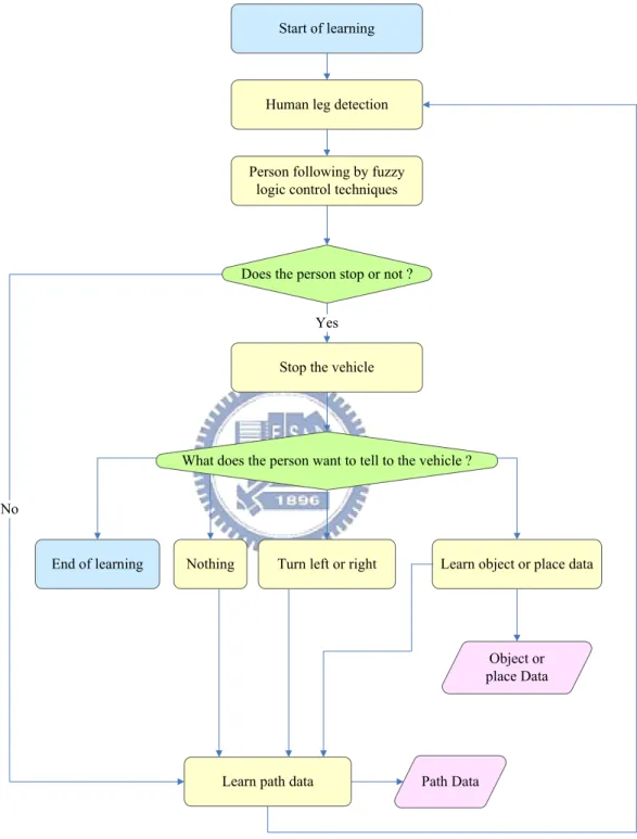
The proposed learning method is based on human following by ultrasonic signals, as mentioned previously. When the vehicle follows a person, it uses the distance between the person’s leg and itself to decide if it has to conduct fine tuning of its direction or not. Then it
has to handle two kinds of situations. If it detects the situation that the person does not stop, it uses the distance as input to the fuzzy controller we design to decide if it has to adjust its running angle and speed or not. However, if the person stops, the vehicle has to stop and then it has to know what the person commands it to do. For this, the following four kinds of situations are handled by the vehicle, as proposed in this study.
(a) (b)
Figure 2.2 The vehicle Pioneer 3 with a notebook used in this study. (a) A front view of the vehicle. (b) A back view of the vehicle.
The first is that the vehicle should turn left or right. The second is that the vehicle should learn the information of objects or places which will be introduced by the vehicle as a guide during navigation. The third is that the person is just too close to the vehicle at the current moment, but the person does not want to stop. In this situation, the vehicle is designed to do nothing and continue learning. In the just-mentioned three kinds of situations, the vehicle is designed to learn the path data in the mean time. The final situation is the end of learning.
These major steps are shown in Figure 2.3.
Start of learning
Does the person stop or not ?
Path Data Human leg detection
Person following by fuzzy logic control techniques
Stop the vehicle Yes
No
What does the person want to tell to the vehicle ?
Learn path data
Turn left or right Learn object or place data Nothing
End of learning
Object or place Data
Figure 2.3 An illustration of proposed process of automatic learning by person following and fuzzy logic control techniques.
2.4
Idea of Proposed Path Analyzing and
Guiding Method
After the vehicle learns the data of paths, objects, and places in the learning stage, it has to analyze the learned data. For this, five kinds of information are identified in this study for use during navigation, as described in the following.
The first is when the vehicle has to turn. If it turns just according to the originally learned position, it may turn too early or too late possibly because of incremental mechanic errors. This may cause the vehicle to hit the wall or to go too close to it after turning. Therefore, we propose a method for deciding when the vehicle has to turn, and combine this method with the result of path analysis.
The second kind of information for use in navigation is the distance between walls in environments. An indoor navigation path usually includes several different environments, like a corridor, an entrance hall, etc. The wall distances in these environments may be not the same. Therefore, the vehicle has to know the wall distances in environments and when to use them. We have designed the fuzzy controller mentioned previously to have such an ability, which will be described in Chapter 5.
The third kind of information for use in navigation is the intolerable distance between the vehicle and obstacles in front of the vehicle. When the vehicle is on a place where it has to turn at the learning stage, it may be blocked by a wall in front of it. Therefore, the vehicle needs to know the intolerable distance to keep itself from hitting the wall. Besides, when a person walks in the front of the vehicle and the person’s leg is detected by ultrasonic sensors, the vehicle also needs to have an idea about how to deal with such a situation.
The fourth kind of information for use in navigation is when to stop. If the vehicle does not have to turn, it needs to know the timing for this action. The final kind of information is
when to introduce to objects or places as a guide. The major steps are illustrated in Figure 2.4.
2.5
Idea of Proposed Vehicle Navigation
Method
After analyzing the learned path, the vehicle will have the path data of the environment. Then, it can use such information to navigate. The proposed navigation method has two major steps and conducts three tasks. The first step is reading the data of the navigation path which is separated into several segments by the turning nodes obtained from analyzing the learned path. Accordingly, the vehicle can navigate and work as a guide. The second step is navigation in the environment by proposed fuzzy logic control techniques.
In addition, the vehicle is designed in this study to perform three tasks at every path segment. The first task is finding the position of the turning node if this segment is not the final one. The second task is introducing objects or places as a guide if necessary. The third task is stopping navigation when one of the following two situations happens. The first is that an unexpected mistake happens. The second is that this segment is the final one where the vehicle arrives at the end of navigation. These major steps are illustrated in Figure 2.5.
Chapter 3
Human Following by Fuzzy Logic
Control for Path Learning
3.1
Introduction
In this chapter, we introduce the details of the proposed learning procedure. The environmental feature used for learning in this study is path data. In the learning procedure, the vehicle follows a person and learns path data in the mean time. In Section 3.2, we describe how to gather path data when the vehicle follows a person in an indoor environment. In Section 3.3, we review the fundamental fuzzy control theory and describe the principle of a fuzzy logic controller which we design for this study. In Section 3.4, we describe how to use fuzzy logic control techniques in the proposed method. Furthermore, we describe how to detect and handle three kinds of situations which happen when the person stops and after the vehicle stops in Section 3.5. Finally, we summarize the above-mentioned techniques and describe an algorithm of the proposed learning procedure in Section 3.6. An illustration of the learning procedure is shown in Figure 3.1.
3.2
Learning of Path Data
While the vehicle follows a person, it learns path data in the mean time. For this, it will obtain four kinds of information from different sources, as identified in this study.
Figure 3.1 Illustration of proposed learning procedure.
First, the odometer provides the speed information of the vehicle. Second, the computer provides the information of the running time of the program which controls the vehicle. Third, the ultrasonic sensors provide the distance information with respect to surrounding objects
and walls. The ultrasonic sensors equipped in the vehicle include fore and aft sonar arrays. The sonar positions in all sonar arrays are fixed: one on each side and six facing outward at 20-degree intervals. The fore sonar array of the vehicle is shown in Figure 3.2(a). A simple illustration of the fore and aft sonar arrays is shown in Figure 3.2(b). Fourth, the person provides the command information with regard to surrounding environments. The command information is that describing the ways the person interacts with the vehicle. For example, if the vehicle detects that the person stops, it will stop, too. In other words, the command information does not mean the information which the operator of the vehicle keys in by hand.
Besides, in order to draw a map to show on the screen of a computer, the vehicle also
records the position information which consists of the coordinates (x, y, θ) in the world
coordinate system provided by the odometer. A list of all kinds of the learned information is shown in Table 3.1.
Table 3.1 All kinds of the learned information.
Type Explanation
Command 1 This item records that this node is the first or final one of a path or
not.
Command 2
This is the person’s command.
The vehicle receives it by analyzing the ultrasonic signals and the person’s behaviors.
It includes going front, stopping, restarting, turning, and introducing objects.
Speed This is the speed of the vehicle.
Coordinate (x, y, θ) x and y are coordinates on Cartesian coordinate system.
θ is the direction of the vehicle.
Time This is the information of running time of the program which
controls the vehicle.
Angle This is part of the person’s command and represents the angle which
the vehicle has to turn
Distances This is an array with 16 elements and represents every distance
1 2 3 4 5 6 0 Front 7 Left Right autonomous vehicle No.4, 10° No.5, 30° No.6, 50° No.7, 90° No.2, -30° No.3, -10° No.1, -50° No.0, -90°
(a) The fore sonar array of the vehicle.
(b) The fore and aft sonar arrays. Figure 3.2 Illustration of sonar arrays
1 2 3 4 5 6 0 Front 7 14 13 12 11 10 9 15 Back 8 Left Right
3.3
Review of Design Principle of Fuzzy
Logic Control System
3.3.1 Fuzzy sets and membership functions [18]
According to Lin and Lee [18], a classical (crisp) set is a collection of distinct objects that can be separated into two groups, members and nonmembers, by a characteristic function defined as Eq. (3.1):
( )
1 ; 0 . A if and only if x A x if and only if x Aμ
= ⎨⎧ ∈∉ ⎩ (3.1)In Eq. (3.1), A is a classical set, x is an element, and μ is a characteristic function of A.
Furthermore, the boundary of a classical set A is rigid and sharp.
On the other hand, a fuzzy set introduces vagueness by eliminating the sharp boundary that divides members from nonmembers in the group. It is defined as a set of ordered pairs by:
( )
(
)
{
,}
A
A%= x
μ
% x x∈U . (3.2)In Eq. (3.2), A% is a fuzzy set in the universe of discourse U, and x is an element of U.
In addition, μ is a membership function (characteristic function) of A% and
( )
A x
μ
% is thegrade (or degree) of membership of x in A%, which indicates the degree that x belongs to A%.
The range of μ is a subset composed by the nonnegative real numbers whose supremum is
finite.
An example of characteristic functions of a classical set A and a fuzzy set A% is shown
0
1
3
( )
1
0
3;
3.
Aif x
x
if x
μ
= ⎨
⎧
≥
<
⎩
A(x)
(a) An example of characteristic function of a classical set A.
0
1
3
1
5
( )
1 1 3; 2 3 1 3 5; 2 0 1 5. A x if x and x x x if x and x if x or xμ
− ⎧ ≥ < ⎪ ⎪ = ⎨ − + ≥ < ⎪ ⎪ < > ⎩ %x
( )
A xμ
%(b) An example of membership function (characteristic function) of a fuzzy set A%
Figure 3.3 An example of characteristic functions of a classical set A and a fuzzy set
3.3.2 Basic architecture of a fuzzy logic controller [18]
According to Lin and Lee [18], the basic architecture of a fuzzy logic controller is shown in Figure 3.4. It is comprised of four principle components. The first is fuzzifier. The observed data are usually crisp. Therefore, a fuzzifier will be utilized to convert the data into fuzzy numbers (fuzzy data) using membership functions.
The second is fuzzy rule base. It is a collection of fuzzy control rules characterized by fuzzy IF-THEN rules. In the case of multi-input-single-output systems, the general form of the fuzzy control rules is:
Ri: IF x is Ai,…, AND y is Bi, THEN z = Ci, i = 1, 2, …, n, (3.3)
where x, …, y are linguistic variables representing the process state variables, and z is a
linguistic variable representing the control variable. Ai,…, Bi, and Ci are linguistic values of
the linguistic variables x, …, y, and z.
States or Outputs
Fuzzifier Inference
Engine Defuzzifier Plant
Fuzzy Rule base
μ(x) μ(y) y x
x
Figure 3.4 Basic architecture of a fuzzy logic controller. [18]
function. It is a basic operation of fuzzy sets.
The third is inference engine. It imitates people to make decisions according to fuzzy if-then rules and fuzzy reasoning. The forth is defuzzifier. It transforms the result in the space of fuzzy control actions into some actions in the space of nonfuzzy (crisp) control actions.
3.4
Proposed Fuzzy Logic Control
Techniques for Human Following
3.4.1 Proposed method for controlling vehicle direction
The sonar positions in the sonar arrays shown in Figure 3.2 are not directly in front of the vehicle. Therefore, if the vehicle moves straight and follows a person as shown in Figure 3.5(a), it can not detect the person by ultrasonic sensors. However, if it moves on a curve path as shown in Figures 3.5(b) or 3.5(c), it will detect the person by ultrasonic sensors. In order to keep following the person, the vehicle has to keep the person’s position directly in front of it. However, it may move on a curve path because of incremental mechanic errors or the person may not walk on a straight path. For this, if it detects that the person is on the left hand side of it as shown by Figure 3.5(b), then it can know that it is moving on a curve path and adjusts its direction by turning left. Similarly, if it detects that the person is on the right hand side of it as shown by Figure 3.5(c), then it can know that it is moving on a curve path and adjusts its direction by turning right. In addition, in order to improve the chance that it can detect the person by ultrasonic sensors, the values detected from ultrasonic sensors No. 2, 3, 4, and 5 will be used as the inputs of the proposed fuzzy controller.
(a) (b) (c)
Figure 3.5 Three kinds of relative positions of the vehicle and a person. The blue circle represents the person and the arrows represent the signals of the ultrasonic sensors equipped in front of the vehicle. (a) The vehicle moves on a straight path. (b) The vehicle moves on a curve path. (c) The vehicle moves on a curve path.
According to this idea, the input variables for the proposed fuzzy controller are D2, D3,
D4, and D5, which represent the values measured from ultrasonic sensors No. 2, 3, 4, and 5.
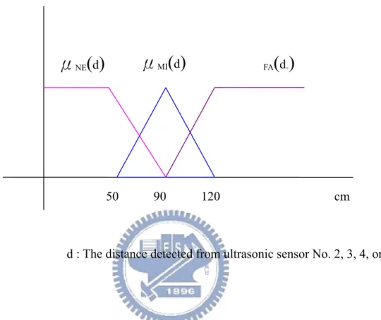
The controlled linguistic variable is denoted as ANGLE, which represents the angle and direction of the vehicle’s rotation. Three fuzzy terms are defined for each input variables. They are near (NE), middle (MI), and far (FA). The membership functions of the three fuzzy terms, NE, MI, and FA, are illustrated in Figure 3.6. Furthermore, seven fuzzy terms are denoted for the controlled linguistic variable. They are from negative large to positive large. The negative large means that the vehicle turns a large angle to the left. Similarly, the positive
seven fuzzy terms of the linguistic variable ANGLE is illustrated in Figure 3.7.
Figure 3.6 The membership functions of the three fuzzy terms, NE, MI, and FA.
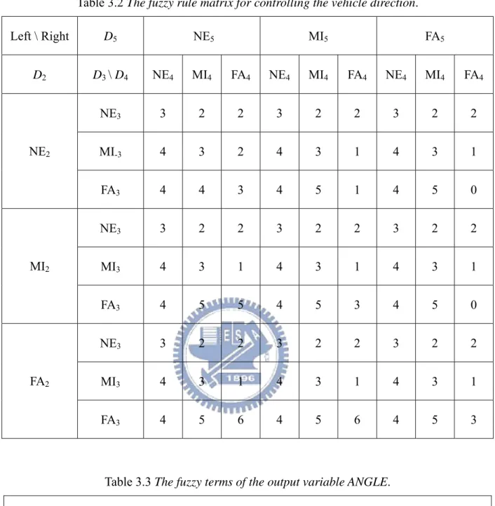
A total of 81 fuzzy rules are represented as a fuzzy rule matrix which is shown in Table 3.2, and the fuzzy terms of the output variable ANGLE is represented as seven numbers which are described in Table 3.3. The form of each fuzzy rule is:
Ri : IF D
2 is Ak, D3 is Bk, D4 is Ck, AND D5 is Ek, THEN ANGLE is Fj. (3.4)
In Eq. (3.4), Ak, Bk, Ck, and Ek represent the linguistic values of the three fuzzy terms, NE, MI,
and FA, respectively. Furthermore, Fj represents the linguistic values of the seven fuzzy terms
of the output variable.
The degree that d belongs to NE, MI, or FA.
μ
NE(
d)
d : The distance detected from ultrasonic sensor No. 2, 3, 4, or 5.
μ
FA(
d-)
50 90 120 cm
Table 3.2 The fuzzy rule matrix for controlling the vehicle direction. Left \ Right D5 NE5 MI5 FA5 D2 D3 \ D4 NE4 MI4 FA4 NE4 MI4 FA4 NE4 MI4 FA4 NE3 3 2 2 3 2 2 3 2 2 MI-3 4 3 2 4 3 1 4 3 1 NE2 FA3 4 4 3 4 5 1 4 5 0 NE3 3 2 2 3 2 2 3 2 2 MI3 4 3 1 4 3 1 4 3 1 MI2 FA3 4 5 5 4 5 3 4 5 0 NE3 3 2 2 3 2 2 3 2 2 MI3 4 3 1 4 3 1 4 3 1 FA2 FA3 4 5 6 4 5 6 4 5 3
Table 3.3 The fuzzy terms of the output variable ANGLE.
ANGLE
Left-hand rotation--- straight --- Right-hand rotation Large angle of rotation ---zero--- Large angle of rotation
0 1 2 3 4 5 6
Finally, the method used to defuzzify the fuzzy output is the discrete fuzzy centroid defuzzification.
Figure 3.7 The membership functions of the seven fuzzy terms of the controlled linguistic variable ANGLE.
3.4.2 Proposed method for controlling vehicle speed
When the vehicle follows a person, the moving speed of the person may not be a constant. For this, after adjusting its direction, it still has to adjust its speed to keep following the person. The relationship between the person’s speed and the vehicle’s speed is an important factor in the proposed method. For example, if the person walks faster than the vehicle, the vehicle should speed up. The proposed system retrieves the distance information
Di which includes the values (d2,i, d3,i, d4,i, d5,i) measured respectively from ultrasonic sensors
No. 2, 3, 4, and 5 at time i. The person’s speed is estimated by the two variables, Di and Di-1.
Three input linguistic variables are used in the designed fuzzy controller. They are the -3.5 -3 -2.5 -2 -1.5 -0.5 0 0.5 1.5 2 2.5 3 3.5
θ: the angle which the vehicle needs to turn.
μ
0(
θ)
μ
1(
θ)
μ
2(
θ)
μ
3(
θ)
μ
4(
θ)
μ
5(
θ)
μ
6(
θ)
0 1distance di measured at time i (DN), the distance di-1 measured at time i−1 (DL), and the speed
of the vehicle at time i (SV). In the learning stage, we assume that only one person is in front
of the vehicle. Therefore, at time i, the input value di of the variable DN is the minimum
values of d2,i, d3,i, d4,i, and d5,i, and the input value di-1 of the variable DL is the minimum
values of d2,i-1, d3,i-1, d4,i-1, and d5,i-1. However, a wall may also be in front of the vehicle when
the vehicle is at a corner. In order to deal with this situation, the variables, DN and DL, have
the fuzzy terms respectively to do this work. This fuzzy term is UB which will be defined in the following paragraph. The main idea to define this fuzzy term is that if the input value d is very large, then it belongs to this fuzzy term with a large degree, because it can not be used to
decide what in front of the vehicle is, the person or a wall.
Six fuzzy terms are defined for each of the input variables, DN and DL. They are nearer
(NE), near (N), middle (MI), far (F), farther (FE), and unbelieving (UB). The term UB is used when the distance is too far to decide whether it is to the person or a wall. The membership functions of these fuzzy terms are illustrated in Figure 3.8.
Furthermore, five fuzzy terms are defined for the input variable SV. They are slower (SE),
slow (S), middle (MD), fast (FS), and faster (FR). The membership functions of these fuzzy terms are illustrated in Figure 3.9.
The output linguistic variable which is denoted as SA represents speed. If the vehicle’s
speed is Vi at time i and the controller outputs a result sa which is the output value of SA, then
the vehicle’s speed at time i+1 is represented as Vi+1 and obtained by Vi+1 = Vi + sa. In other
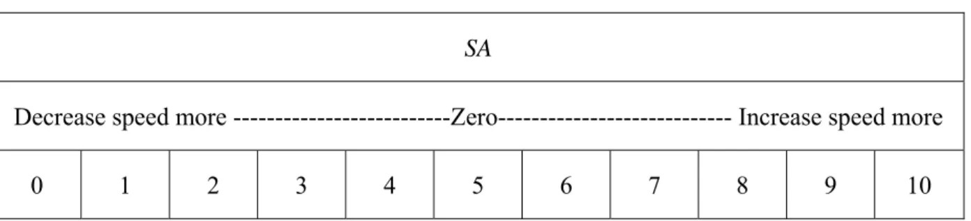
words, the result of the controller is a difference of the vehicle’s speeds at time i and i+1. Eleven fuzzy terms are defined for the output variable. They are from negative large (0) to positive large (10). The negative value means that the vehicle has to decrease its speed. The membership functions of these fuzzy terms are illustrated in Figure 3.10.
Figure 3.8 The membership functions of the six fuzzy terms, NE, N, MI, F, FE, and UB.
A total of 180 fuzzy rules are represented as a fuzzy rule matrix which is shown in Table 3.4, and the fuzzy terms of the output variable SA are described in Table 3.5. The form of each fuzzy rule is:
Ri : IF D
N is Ak, DL is Bk, AND SV is Ck, THEN SA is Ej, (3.5)
In Eq. (3.5), Ak and Bk represent the linguistic values of the six fuzzy terms NE, N, MI, F, FE,
and UB, respectively. Ck represent the linguistic values of the five fuzzy terms SE, S, MD, FS,
and FR. Furthermore, Ej represents the linguistic values of the seven fuzzy terms of the output
variable.
Finally, the method used to defuzzify the fuzzy output is the discrete fuzzy centroid defuzzification.
The degree that d belongs to NE, N, MI, F, FE, or UB.
μ
NE(
d)
d : the distance obtained by the above-mentioned way.
42.5 55 110 cm
μ
N(
d-)
67.5 80 92.5μ
MI(
d)
μ
F(
d)
μ
FE(
d)
μ
UB(
d)
Figure 3.9 The membership functions of the five fuzzy terms of the input variable SV.
Figure 3.10 The membership functions of the eleven fuzzy terms of the output variable SA. -18 -15 -12 -9 -6 -3 0 3 6 9 12 15 18
μ
0(
a)
μ
5(
a)
μ
10(
a)
0 1The degree that a belongs to the fuzzy terms of the output variable SA
cm / s a: difference of the vehicle’s speeds at time i and i+1 The degree that s belongs to SE, S, MD, FS, or FR.
μ
SE(
s)
20 30 cm / sμ
S(
s)
40 50 60μ
MD(
s)
μ
FS(
s)
μ
FR(
s)
Table 3.4 The fuzzy rule matrix for controlling the vehicle’s speed. DN DL \ SV SE S MD FS FR NE 5 4 2 1 1 N 4 4 2 1 0 MI 4 3 1 0 0 F 3 3 1 0 0 FE 3 2 1 0 0 NE UB 4 3 2 0 0 NE 6 5 3 2 2 N 5 5 3 2 1 MI 4 4 2 1 1 F 4 4 2 1 0 FE 3 3 2 1 0 N UB 6 5 3 1 1 NE 8 6 5 4 3 N 7 6 5 4 3 MI 6 5 4 3 2 F 6 5 4 3 2 FE 5 4 4 3 2 MI UB 8 7 5 3 1 NE 10 8 7 7 6 N 10 8 7 6 5 MI 9 8 7 6 5 F 9 7 6 5 4 FE 8 7 6 5 3 F UB 9 8 6 5 4 NE 10 9 8 8 7 N 10 9 8 7 6 MI 10 9 8 7 6 F 10 8 7 6 5 FE 9 8 7 6 5 FE UB 10 9 7 6 5 NE 4 3 2 1 0 N 5 4 3 2 1 MI 6 5 4 3 2 F 7 6 5 4 3 FE 8 7 6 5 4 UB UB 5 5 5 4 4
Table 3.5 The fuzzy terms of the output variable SA.
SA
Decrease speed more ---Zero--- Increase speed more 0 1 2 3 4 5 6 7 8 9 10
3.5
Vehicle Stopping, Turning, and
Restarting Techniques
3.5.1 Stopping technique
When the vehicle follows a person, if the person stops, the vehicle has to stop, too. It is desired that if the person is near the left- or right-hand side of the vehicle, then the vehicle should stop. In other words, if the distance detected from ultrasonic sensors Nos. 0, 7, 8, or 15 is smaller than a preselected value, then the vehicle should stop.
3.5.2 Turning technique
If the vehicle stops according to the stopping technique mentioned in Section 3.5.1, it has to know what the person commands it to do. In this study, it can receive four kinds of commands by analyzing the ultrasonic signals and the person’s behaviors. These commands are represented as TURN, RECORD, WALK, and END. The command TURN means that the vehicle is at a turning node and it has to turn. The command RECORD means that the vehicle is at a node where it will introduce an object or a place as a guide during navigation. In order to achieve this task, it records this node. The command WALK means that the vehicle is not at a node where it turns, a node where it will introduce an object or a place as a guide, or a node
which is the end of this path. Therefore, it continues to follow the person without turning or recording any object’s position. The command END means that the vehicle is at the end of the learning path. Therefore, it should record this node and finish learning.
In order to obtain the just-mentioned commands, the vehicle uses a voting technique to analyze the ultrasonic signals and the person’s behaviors. It detects the person’s position by the ultrasonic sensors. After it stops, it still receives values from the ultrasonic sensors n times
and these values are represented as SD1, SD2, …, SDn, where n is a threshold we set in
advance. Each SDi includes 16 values (sd0, …, sd15) from the respective 16 ultrasonic sensors.
If sdk in SDi is less than 40% of sdk in SD1, then ultrasonic sensor No. k gets a vote. After
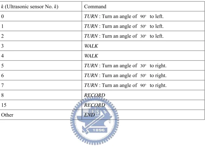
voting, if the votes got by ultrasonic sensor No. k are the most and more than a threshold T we set, the vehicle will execute a command which is represented by ultrasonic sensor No. k. Ultrasonic sensors Nos. 0, 1, 2, 5, 6, and 7 represent the command TURN. Ultrasonic sensors Nos. 8 and 15 represent the command RECORD. Ultrasonic sensors Nos. 3 and 4 represent the command WALK. In addition, if several ultrasonic sensors get the same number of votes and their respective votes are all more than the threshold T, a sequence of priority of the commands is used. This sequence of priority is TURN > RECORD > WALK. However, if all of these three commands, TURN, RECORD, and WALK are not selected, the vehicle will execute the command END. A list of the ultrasonic sensors and the commands represented by them respectively is shown in Table 3.6. The algorithm of the turning technique is shown in Algorithm 3.1.
3.5.3 Restarting technique
After the vehicle executes the person’s command as mentioned previously, it detects if the person is in front of it or not. If the answer is yes, then it restarts to follow the person. However, if the answer is no, it waits a period of time and continues to detect during this
period of time. Afterward, if the answer does not change, then it will finish learning.
Table 3.6 List of the ultrasonic sensors and commands represented by them, respectively.
k (Ultrasonic sensor No. k) Command
0 TURN : Turn an angle of 90° to left.
1 TURN : Turn an angle of 50° to left.
2 TURN : Turn an angle of 30° to left.
3 WALK
4 WALK
5 TURN : Turn an angle of 30° to right.
6 TURN : Turn an angle of 50° to right.
7 TURN : Turn an angle of 90° to right.
8 RECORD
15 RECORD
Other END
Algorithm 3.1 Getting a command by analyzing the ultrasonic signals and the person’s behaviors.
Input: The ultrasonic signals SD1, SD2, …, SDn measured after the vehicle stops.
Output: One of the four kinds of commands TURN, RECORD, WALK, and END. Steps:
Step 1. Set i = 1.
Step 2. If sdk in SDi is less than 40% of sdk in SD1, then ultrasonic sensor No. k gets a vote, k
= 0, 1, 2, …, 15.
Step 3. Repeat Step 2 until i = n. If i > n, then go to step4.
Step 4. Compute how many votes got by every ultrasonic sensor respectively. Step 5. Compute which ultrasonic sensor gets the most votes.
Step 6. If only an ultrasonic sensor gets the most votes and these votes are more than the threshold T, then go to Step 7. (Assume that this ultrasonic sensor’s number is k1). If more than one ultrasonic sensor gets the most votes and the votes of each
sensor are more than the threshold T, then go to Step 8. (Assume that these ultrasonic sensors’ numbers are k1, k2, …, and kj).
If no ultrasonic sensor gets enough votes which are more than the threshold T, then output the command END and finish this procedure.
Step 7. Set w = k1, and then go to Step 9.
Step 8. According to the sequence of priority of the commands TURN > RECORD > WALK, set w = kx, where x = 1, 2, …, or j and go to Step 9.
Step 9. According to the ultrasonic sensor’s number w and Table 3.4, output the command represented by w.
3.6
Algorithm of Proposed Method for Path
Learning
In this section, an integral algorithm of the proposed learning procedure is described. As mentioned previously, the proposed learning procedure includes two major tasks, following a person and learning a path in the mean time. At first, the vehicle follows a person and adjusts its direction and speed by the ultrasonic signals and fuzzy logic control techniques. If the person stops, it stops to detect what the person commands it to do by analyzing the ultrasonic
signals and the person’s behaviors. Then it continues learning until the person commands it to finish. The integral algorithm of proposed method for path learning is shown in Algorithm 3.2.
Algorithm 3.2 Learning a path by following a person. Input: A vehicle and a user.
Output: A guiding path data. Steps:
Step 1. Follow the user.
Step 2. Adjust its direction and speed by the proposed fuzzy controllers described in Section 3.4 and save the information of each node. All kinds of information of a node to learn are shown in Table 3.1.
Step 3. If the person stops, then stop and go to step4, else go to Step2.
Step 4. Analyze the person’s behaviors and obtain a command by Algorithm 3.1. Step 5. Execute this command and save the information of this command.
If this command is not END, go to Step 6, else go to Step 7. Step 6. Wait until the person stands in front of it.
If the person stands in front of it, go to Step 1.
If the person never stands in front of it during a period of time, go to Step 7. Step 7. Save the information of this node and finish learning.
Chapter 4
Path Analysis Using Ultrasonic Signals
4.1
Introduction
We introduce the details of the proposed procedure of path analysis in this chapter. The environmental feature obtained from path analysis and used for navigation is path data. When the vehicle learns path data by following a person, the trajectory of the path may be rough and curvilinear. After learning, it is so desired also that the vehicle can plan a navigation path to follow the sequences of objects which it has to introduce as a guide without hitting walls in environments. For this, the path data for navigation are identified by five kinds of information in this study. In other words, the structure of the learned path data is not the same as that of the path data for navigation. We describe the structure of the path data for navigation in Section 4.2. In Section 4.3, we describe how to analyze the learned path data mentioned in Section 3.2 and obtain the path data for navigation described in Section 4.2. Finally, we summarize the above-mentioned techniques and describe an integral algorithm of the proposed procedure of path analysis in Section 4.4. An illustration of the proposed procedure of path analysis is shown in Figure 4.1.
4.2
Path Data for Navigation
As just-mentioned, the path data for navigation are identified by five kinds of information in this study. In this section, we describe the details of these kinds of information. They are denoted as TTURN, WDIS, IDIS, TSTOP, and TOBJECT.
Analyzing
Start of path analysis
Is there any
segment of the above segments not been handled ?
Learned Path Data Separate path into several segments
according to every turning point
Read the data of the segment which is the
first one of the segments not been handled End of path analysis Yes
No
Is this segment the final one of total segments ?
Analyze when to turn
Analyze when to stop
Analyze the intolerable distance between the vehicle and obstacles in front of it Analyze wall distances in environments and when to use them on designed fuzzy
logic control systems when navigation
Analyze when to introduce objects or places
Object or place Data Yes
No
Path Data for Navigation
The first kind of information TTURN is about when to turn. It includes three major items. The first item is TDIRECT. It records the tuning direction of a turning node obtained from the learned path data directly. The second item is NDETECT. Consider the case that the vehicle turns left on a turning node during learning. It should not detect anything on its left-hand side for a period of time from arriving at the turning corner to arriving at the turning node. This period of time is just what is meant by the second item. If the vehicle navigates on the same path next time, it can use this information to know when to turn. However, this information is not enough to deal with all situations. Sometimes, when the vehicle desires to turn left on the same turning corner by itself after learning, it may detect nothing on its left-hand side for the same period of time as specified by NDETECT even if it does not arrive at the turning corner, because walls in environments are not always connected everywhere. Therefore, an item is used to deal with such the situation, which is the third item of TTURN, named BEFORE. It means that the vehicle can not turn when its running time is not over this value. In other words, the vehicle is not regarded close to the turning corner before the period of time specified BEFORE elapses. An example of TTURN is illustrated in Figure 4.2.
The second kind of information WDIS is distances between walls in environments. It includes three major items named as WNUM, WVALUE, and WTIME. Wall distances in
different environments may not be the same. Therefore, the vehicle has to know the wall
distances in learned environments and when to use them. Furthermore, environments between two turning nodes may also be different. For this, the first item WNUM is defined as the number of distinct wall distance values. The second item WVALUE records each value of the wall distances. The item WTIME records when to use the respective wall distances of
WVALUE.
The third kind of information IDIS is the intolerable distance between the vehicle and obstacles in front of the vehicle. The vehicle should know this information to keep itself from hitting obstacles or walls in front of it. The fourth kind of information TSTOP is when to stop.
If the vehicle does not have to turn, it needs to stop at the end node of a path of navigation. The fifth kind of information TOBJECT is when to introduce objects or places as a guide and includes two major items. They are named ONUM and OTIME and represent the number of objects which the vehicle needs to introduce and the time when to introduce the objects, respectively. All above-mentioned kinds of the information of the path data for navigation are listed in Table 4.1.
4.3
Techniques for Path Analysis
In this section, we describe how to obtain the five kinds of information as mentioned in Section 4.2.
Time of BEFORE
Starting node Turning node Time of
NDETECT
At first, a learned path is segmented into several pieces by the turning nodes before being analyzed, and each segment is given a record in this study, which includes these five kinds of information.
Table 4.1 All kinds of the information of the path data for navigation.
Type Items (if exist) Meaning
TDIRECT This is the turning direction obtained from the learned path
data directly.
NDETECT This is a period of time from arriving at a turning corner to
arriving at the turning node.
TTURN
BEFORE The period of time before which the vehicle can not turn.
WNUM The number of the wall distances.
WVALUE This records each value of the wall distances.
WDIS
WTIME This records when to use the respective wall distances of
WVALUE.
IDIS ( no item) This is the intolerable distance between the vehicle and
obstacles in front of the vehicle.
TSTOP ( no item) This is when to stop.
ONUM The number of objects which the vehicle needs to
introduce.
TOBJECT
OTIME This records when to introduce the objects, respectively.
4.3.1 Turning
In this section, we describe how to obtain the information TTURN. The turning direction is obtained from the learned path data directly. Denote the distance from a turning corner to
values by ultrasonic sensors on the turning direction from the position of the turning corner to
that of the turning node. Therefore, we can obtain Dturn by computing the recorded
information of its running time and speed from the turning node back to the starting position of the turning corner. In other words, if the starting position of the turning corner is
represented as Pc, the position of the turning node is represented as Pt, the speed of the vehicle
is represented as SVi, and the vehicle’s running time between the position i to i+1 is
represented as Ti, then we have
Dturn = Pt − Pc = ∑i((SVi + SVi-1) / 2) × Ti,
where i is from c to t. However, the vehicle may also detect very large distance values by
ultrasonic sensors before arriving at Pc, for example, when a door in an environment is
opened, or when the environment includes more than one crossroad, etc. In these situations, if the vehicle detects very large values by ultrasonic sensors continuously for a period of time in an environment, then we should deal with them additionally. Let the distance, which the vehicle goes across during the period of time in such a kind of situation, be represented as
Dspace, j, where j is the number of such special environments. A segment of the learned path
data may have several such distances. The maximum value of all Dspace, j is denoted as Dspace.
Note that all Dspace, j must occur before Dturn, because a turning node is the last node of a
segment of a learned path. Figure 4.3 is an example to explain the just-mentioned idea.
In Figure 4.3, this segment includes an opened door and two crossroads. The opened
door is from the position Ps1 to the position Ps2, the first crossroad is from Ps3 to Ps4, and the
second crossroad is the turning corner. Dspace, 1 is the distance between Ps1 and Ps2, Dspace, 2 is
the distance between Ps3 and Ps4, and Dspace is the maximum value of Dspace, 1 and Dspace, 2. In
Figure 4.3 An example to explain the idea of turning.
According to the relationship between Dturn and Dspace, the system needs to consider three
kinds of situations. The first is Dspace < Dturn. In this situation, the vehicle can decide that the
distance which it goes across is Dturn or Dspace, j during navigation, because Dturn is larger than
all Dspace, j. The second is Dspace ≥ Dturn. As shown in Figure 4.3, if Dspace, 1 < Dturn and Dspace, 2 >
Dturn, then Dspace > Dturn. In this situation, a position Pe which is between Ps3 and Ps4 exists and
it satisfies that Pe −Ps3 = Dturn. If the vehicle only uses Dturn to decide whether it needs to turn
or not, it will turn at the position Pe. However, it should not do so, because Pe is not the
correct turning node. In order to deal with this situation in general cases, a condition is used,
that is, the vehicle can not turn when it is not over a position PB, and the position PB has to
satisfy the constraint that all Dspace, j must occur before PB. In the just-mentioned second
situation, the system can set PB = Pc. However, if Dturn is too large as shown in Figure 4.3, the