國
立
交
通
大
學
網路工程研究所
碩
士
論
文
混合式具路徑感知識別碼之分配與繞徑機制
A Hybrid Path-aware Identity Assignment and Routing
Mechanism
研 究 生:張乃心
指導教授:曾建超 教授
混合式具路徑感知識別碼之分配與繞徑機制
A Hybrid Path-aware Identity Assignment and Routing Mechanism
研 究 生:張乃心 Student:Nai-Hsin Chang
指導教授:曾建超 Advisor:Chien-Chao Tseng
國 立 交 通 大 學
網 路 工 程 研 究 所
碩 士 論 文
A ThesisSubmitted to Institute of Network Engineering College of Computer Science
National Chiao Tung University in partial Fulfillment of the Requirements
for the Degree of Master
in
Computer Science
July 2007
Hsinchu, Taiwan, Republic of China
混合式具路徑感知識別碼之分配與繞徑機制
學生:張乃心
指導教授:曾建超 博士
國立交通大學網路工程研究所碩士班
摘 要
本篇論文提出一套混合式具路徑感知識別碼(Hybrid Path-aware Identity, HPID)的分配與繞徑機制,本機制將現有之具路徑感知識別碼(Path-aware Identity, PID)的分配機制加以整合,可針對不同網路拓樸,達到有效的識別碼分發。 PID 係指識別碼本身隱含繞徑資訊,其編碼經運算後可以達到路徑選擇的目 的。PID 的使用不僅可以免除管理繞送路徑的繁複訊息,同時也可避免建立繞送路 徑所產生的延遲。 然而各方所提之 PID 機制皆有某些限制與缺失,僅適用於部分網路環境。因 此,本篇論文提出之混合式具路徑感知識別碼(Hybrid Path-aware Identity, HPID) 乃針對不同實體分佈之需求,對識別碼加以規劃切割,並結合不同 PID 分配與繞 徑機制,達到各機制間的特性整合。因此,HPID 除了具有 PID 的特性及優點外, 亦能根據不同實體分佈環境採用適性化的識別碼分配與繞徑機制。 根據模擬結果顯示,本機制可大幅提升各網路實體取得識別碼之成功率,進 而縮短識別碼,降低訊息長度,同時減輕繞徑處理時之運算,達到省電之效用。 關鍵詞:具繞徑感知識別碼、混合式識別碼、混合式繞徑、無線感測網路、ZigBee
A Hybrid Path-aware Identity Assignment and Routing Mechanism
Student:Nai-Hsin Chang
Advisor:Dr. Chien-Chao Tseng
Institute of Network Engineering
National Chiao Tung University
ABSTRACT
In this thesis, we propose a mechanism that can assign Path-aware IDentity (PID) much more efficiently by integrating two or more different PID assignment mechanisms based on the un-derlying network topologies. PIDs are identities that encode routing information into the val-ues of PIDs so that network entities can deduce routing paths from PIDs simply by performing mathematical operations on PIDs without exchanging routing messages. Therefore, PID as-signments not only can eliminate the maintenance overhead of routing tables but also reduce the routing delay.
However, conventional PID mechanisms have their own intrinsic limitations and cannot operate efficiently in various network environments. This thesis proposes a Hybrid Path-aware IDentity (HPID) assignment and routing mechanism that can combine two or more PID mechanisms in accordance of the underlying network topology. Based on the characteristics of the network environment, the HPID mechanism divides an identity into several partitions and adopts a specific PID assignment and routing mechanism for each partition. As a consequence, the HPID mechanism can inherit the salient features and advantages of different PID mecha-nisms, and thus can adapt to various network environments.
The simulation results show that the HPID mechanism significantly increases the success probability for an entity to acquire a unique identity. Furthermore, it also can shorten the iden-tity length and the computing overhead in routing path selection, and thus reduces the power consumption of each network entity.
誌
謝
首先,我要感謝我的指導教授⎯曾建超老師。感謝老師這兩年來的指導與啟 發,即使對於大學時非專攻網路的我,亦不吝惜的給予指教,讓我能夠針對興趣 有所發揮。在這學習的過程中,也讓我體認到積極奮發與創意思考為研究之要務。 同時要感謝曹孝櫟教授、紀光輝教授與蘇坤良教授於百忙之中撥冗審閱我的 論文並擔任口試委員,老師們所提供的寶貴建議使本篇論文更為完善,也感謝老 師們對我的鼓勵與指導。 本篇論文的初始構想,源自於王瑞堂學長,又稱 RT。謝謝 RT 一直以來的支 持與指導,讓我的論文在危機時有了轉機,乃至如今的成果。RT 在學術上不但給 予我思考的方向,在課業之餘又是撞球、慢跑、登山以及羽球好手。他的熱情以 及無窮的創新能力讓我非常佩服,再次感謝 RT,亦祝福他一切順利。☺ 此外,我要感謝劉合翰同學。本篇論文的成形多虧合翰的協助,尤其第四章 的討論亦是因此才有了靈感。我們經過無數次的討論與激盪,終於讓本篇論文更 為完整,在這過程中,我深刻體會到合翰於解決事物時的專精以及超強的組織與 分析能力。合翰是一個很值得我學習的對象,無論是處事態度、思考能力等等, 不但見解獨到精闢,亦有追根究底的精神。能夠和他合作,真是受益良多。 最後,謝謝我的家人,讓我在疲累時有所依歸,他們是我不斷前進的原動力。
Contents
Abstract in Chinese ...i
Abstract in English...ii
Acknowledgements...iii
Table of Contents...iv
List of Figures ...vi
List of Tables...viii
Chapter 1 Introduction... 1
1.1 Motivation ... 1
1.2 Objective... 3
1.3 Synopsis... 3
Chapter 2 Related Work... 4
2.1 Structured PID Mechanisms ... 4
2.1.1 ZigBee Distributed Address Assignment Mechanism ... 4
2.1.2 Disadvantages ... 6
2.2 Unstructured PID Mechanisms... 6
2.2.1 Prime DHCP Scheme... 7
2.2.2 Disadvantages ... 7
2.3 Summary... 8
Chapter 3 HPID Mechanism...9
3.1 HPID Format ... 9
3.2.1 Forward HPID Approach... 12
3.2.2 Backward-HPID Approach with Modification... 15
3.3 HPID Routing Mechanism ... 16
Chapter 4 Discussions of the HPID Mechanism... 20
4.1 Forward Assignment... 20 4.1.1 Leak of Identities ... 20 4.1.2 Quantitative Analysis... 21 4.2 Backward Assignment ... 22 4.2.1 Leak of Identities ... 22 4.2.2 Duplication of Identities ... 23 4.2.3 Quantitative Analysis... 24 4.3 Summary... 24
Chapter 5 Simulation and Analysis ...26
Chapter 6 Conclusions and Future Works ... 32
List of Figures
Figure 2-1 An example of the addresses allocation tree by ZigBee mechanism. ... 5
Figure 2-2 An example of the addresses allocation tree by Prime DHCP scheme. ....7
Figure 3-1. An illustration of the HPID format... 9
Figure 3-2 Part of the distribution of the sensors... 10
Figure 3-3. Configuration of the HPID format. ... 11
Figure 3-4 Forward HPID of the 1st type. ... 12
Figure 3-5 Forward HPID of the 2nd type. ... 12
Figure 3-6 The forward-HPIDs allocation tree. ... 13
Figure 3-7 Backward-HPID of the 1st type. ... 15
Figure 3-8 The backward-HPIDs allocation tree. ... 15
Figure 3-9 The routing procedure via the backward-HPID. ... 18
Figure 4-1 Identities leaking of forward assignment on three segments. ... 20
Figure 4-2 Identities leaking of forward assignment. ... 21
Figure 4-3 Identities leaking of backward assignment on two segments... 22
Figure 4-4 Identities duplication of backward assignment on two segments. ... 23
Figure 4-5 Identities leaking of backward assignment. ... 24
Figure 5-1 An example of network topology for simulation... 26
Figure 5-2 The tree structure via the HPID mechanism. ... 26
Figure 5-3 The failure probability on different identity lengths. ... 27
Figure 5-4 Failure probability on various number of nodes (ID length = 9 bits) ... 29
Figure 5-5 Failure probability on various number of nodes (ID length = 10 bits) ... 29
Figure 5-6 Failure probability on various number of nodes (ID length = 16 bits) ... 29
Figure 5-8 Failure probability on various identity lengths for Prime scheme. ... 31 Figure 5-9 Failure probability on various identity lengths for ZigBee mechanism.. 31
List of Tables
Chapter 1
Introduction
1.1
Motivation
In the tightly connected world today, entities exchange information with messages. En-tities have to recognize each other to transmit data correctly. To recognize an entity, a unique identity is necessary to avoid ambiguity. For example, in a country, people can be recognized with ID cards by the one to one mapping. However, in some situations, duplicate identities are allowed, but the identity should be unique within a local area in general. Identities are also used to manage entities. For instance, students are adminis-trated by student numbers with special compositions. Different segments of the student number represent specific meanings, such as graduated year, department, etc.
Identities have been widely used in networking. For example, in telecom, an op-erator records profile of a subscriber and administrates a user by IMSI (International Mobile Subscriber Identity). Infrastructures use identities to recognize each other, such as BSID (Base Station Identity) and RSID (Relay Station Identity) in WiMAX. In Internet, MAC address and IP address are used for connection and transmitting data in different network layers. Indeed, an identity acts an important role in entity recognition to achieve communication and management.
Several conventional identity assignment mechanisms have been proposed nowa-days and could be categorized as “table-driven” and “path-aware” based on the way to select routing path. Table-driven identity assignment mechanisms assign identity ran-domly and establish routing table for routing path selection, such as DHCP (Dynamic Host Configuration Protocol) [5]. But these mechanisms have some drawbacks. For
in-stance, DHCP needs a centralized server to allocate an identity (IP address) to an entity (host). Therefore, a joining entity has to do server discovery before acquiring identity. Server discovery is a broadcast message and delays identity acquisition process. Besides, routing table entries proliferate with rapidly growing entities. An entity would spend a lot of time looking up a routing table before transmitting data. Routing table mainte-nance also needs great control overhead. However, the proliferating table and the addi-tional maintenance overhead are not allowed in some environments. For example, in wireless sensor networks (WSN), both capabilities and power of devices are limited. Extensive routing table would exhaust memory and extra maintenance messages would consume power. Therefore, table-driven identity assignment mechanisms are not per-mitted under this kind of environment.
In order to solve the problems mentioned above, some experts proposed path-aware mechanisms. Path-aware identity (PID) means an identity has extra routing information within. Instead of using routing table, they establish a tree structure of to-pology after identity assignment and select routing path directly from the tree. For in-stance, ZigBee distributed address assignment mechanism [7] assigns address by opera-tion funcopera-tions based on network settings. Prime DHCP scheme [6] runs a prime num-bering address allocation algorithm to compute unique address for address allocation. Furthermore, PID is assigned distributedly, and entity could acquire PID by itself or from its neighbor. However, these PID mechanisms have some problems. For example, the ZigBee mechanism produces operation functions by configuring limitations of the tree, such as maximum number of children a parent may have, maximum depth of the tree, etc. These limitations will restrict flexibility of the topology changing and some-times they may not be applicable to the network environment practically. In other words, appropriate arranging to tree structure in advance would make identity utilization (1 - failure probability to obtain identity in average) higher. On the contrary, impractical
ar-ranging would cause inefficient use of identity space once topology changes over the limitations. On the other hand, the Prime DHCP scheme uses mathematical operation characteristics based on decomposition of prime-factor number, but it has a serious problem that the tree structure is skew. Skew tree structure is not common to entity dis-tribution and will make identity utilization pretty low.
Therefore, we propose a mechanism to solve the disadvantages resulted from the conventional PID mechanisms and improve identity utilization.
1.2
Objective
In this thesis, we propose a Hybrid Path-aware Identity (HPID) mechanism to integrate the conventional PID mechanisms and combine features of them. HPID mechanism could not only take advantages of PID but also make tree structure more balance and flexible. HPID mechanism configures HPID format according to network requirements. We propose a hybrid assignment mechanism to allocate an HPID of each attached entity. Besides, we also provide a hybrid routing mechanism to make routing procedure oper-ated successfully with HPID.
1.3
Synopsis
The remainder of this paper is organized as follows. Chapter 2 briefly introduces the related research efforts. Chapter 3 explains HPID mechanism, including format con-figuration, assignment and routing mechanisms. Chapter 4 discusses the limitations of our mechanism. Next, evaluation of the conventional PID mechanisms and our mecha-nism are presented in Chapter 5. At least, we conclude this thesis and introduce future works in chapter 6.
Chapter 2
Related Work
Path-aware identity (PID) means an identity contains routing information by certain mathematical operating, and a routing path can be established from the routing informa-tion directly. Therefore, efficient routing is realized without any extensive routing table. Several PID assignment mechanisms have been proposed previously and could be cate-gorized as “structured” and “unstructured” based on the way to produce PID.
2.1
Structured PID Mechanisms
Structured PID assignment mechanism means that it assigns an identity after arranging tree structure. ZigBee distributed address assignment mechanism [20] is a structured mechanism, and we call it the ZigBee mechanism for short in the latter discussion. By the way, classful IP addressing [4] is also a typical example with structured characteris-tic although it isn’t a PID mechanism.
2.1.1 ZigBee Distributed Address Assignment Mechanism
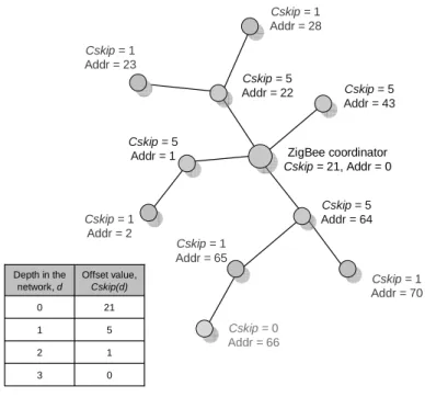
The ZigBee mechanism arranges tree structure by previous network settings, such as the maximum number of children a parent may have (nwkMaxChildren, Cm), the maxi-mum depth in the network (nwkMaxDepth, Lm), and the maximaxi-mum number of routers a parent may have as children (nwkMaxRouters, Rm). It computes the function Cskip(d), essentially the size of the address sub-block being distributed by each parent at the depth to its router-capable child devices for a given network depth, d, as follows:
⎪⎩ ⎪ ⎨ ⎧ − ⋅ − − + = − − ⋅ + = − − otherwise , 1 1 1 if , ) 1 ( 1 ) ( 1 Rm Rm Cm Rm Cm Rm d Lm Cm d Cskip Lm d (1)
Network addresses shall be assigned to end devices in a sequence number with the
nth address, An, given by the following equation, where 1 ≤ n ≤ (Cm-Rm) and Aparent
represents the address of the parent.
n Rm d Cskip A An= parent + ( )⋅ + (2)
This mechanism constructs a tree-structure routing path after allocating identities. Then, an entity could transmit packets according to the computing result of the identity. Figure 2-1 gives an example about how addresses are assigned with the following pa-rameters setting: nwkMaxChildren = 4, nwkMaxRouters = 4, and nwkMaxDepth = 3. In the beginning, a coordinator’s identity is 0 and its calculated Cskip value is equal to 21. The address sequence that the coordinator can assign is, 1, 1+21, 1+21*2, and so on up to the largest address bounded by the address space or the limited nwkMaxChildren. Similarly, an entity having address can calculate its Cskip value and allocate numbers in ascending order to the new entities attached to it. However an entity won’t have any children if the calculated Cskip value is equal to 0.
Cskip = 0 Addr = 66 ZigBee coordinator Cskip = 21, Addr = 0 Cskip = 1 Addr = 28 Cskip = 1 Addr = 23 Cskip = 1 Addr = 2 Cskip = 1 Addr = 65 Cskip = 1 Addr = 70 Cskip = 5 Addr = 43 Cskip = 5 Addr = 1 Cskip = 5 Addr = 64 Cskip = 5 Addr = 22 0 3 1 2 5 1 21 0 Offset value, Cskip(d) Depth in the network, d
2.1.2 Disadvantages
Structured mechanisms have some problems, such as lack of network flexibility and in-efficient use of identity space. Because they all set certain limitations of the network, flexibility of the topology would be reduced. In other words, as the topology changes, entities out of setting ranges could not obtain proper identities. Furthermore, the net-work setting in advance may not be appropriate to the actual netnet-work environment, and then it will waste identities. Namely, in most situations, entities wouldn’t distribute in the whole area averagely but appear in some area frequently, so the identities reserved for the other area won’t be used.
Inefficient use of identity space is a significant problem. In order to satisfy identi-ties requisition of entiidenti-ties, a manager might try to stretch the length of identiidenti-ties to pro-vide more identities. But stretching the length is impracticable in some network envi-ronments. For example, in wireless sensor networks, device capabilities are limited and power saving is undoubtedly a very important issue. Some papers [16] [17] represent that identities with shorter length would diminish computing overhead while routing packets and achieve power saving. On the contrary, stretching identity length would in-crease overhead and consume more power.
2.2
Unstructured PID Mechanisms
Unstructured PID assignment mechanisms, unlike structured ones, have no beforehand network setting or limitations, so they keep flexibility of topology changing. Prime DHCP scheme [6] is one typical example.
2.2.1 Prime DHCP Scheme
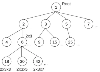
Root 2x3 2x3x3 2x3x5 2x3x7 1 2 3 5 7 25 15 9 6 4 42 30 18 … … … … …Figure 2-2 An example of the addresses allocation tree by Prime DHCP scheme.
Prime DHCP scheme runs a prime numbering address allocation algorithm to compute unique addresses for address allocation and an entity which is considered as a DHCP proxy could acquire an address by itself or from its neighbor. Figure 2-2 gives an exam-ple of addresses a DHCP proxy can assign. The root proxy A has an address of 1 and can allocate prime numbers in ascending order to the new entities attached to it. For a non-root DHCP proxy, it can assign the address equal to its own address multiplied by the unused prime number, starting from the largest prime factor of its own address. Take the entity G with address 6 for example; the largest prime factor of 6 is 3 and the se-quence of addresses entity G can assign is, 6*3, 6*5, 6*7, and so on up to the largest address bounded by the address space. Each node needs to maintain its allocation status to record the last assigned address. After the addresses allocation of all entities, a tree structure will be established, and an entity can select the routing path by computing the destination identity.
2.2.2 Disadvantages
Unstructured mechanisms have some drawbacks. For instance, the Prime DHCP scheme would make the tree structure skew and induce inefficient use of identity space
more poorly. As mentioned before, using identity space inefficiently will induce another problem that the length of identity should be stretched to content the identity requisition of each entity. But stretching identity length is not permitted in some environments, such as wireless sensor network. Although these mechanisms need no extra settings or limitations of the network, the skew tree structure results in other bad effects.
2.3
Summary
Because both structured and unstructured PID assignment mechanisms have their own problems, we want to propose a mechanism to eliminate or reduce these problems, called Hybrid Path-aware Identity (HPID) mechanism. HPID mechanism not only inte-grates structured and unstructured mechanisms but also uses identity space efficiently. In the following section we will introduce our mechanism.
Chapter 3
HPID Mechanism
Whereas the drawbacks of the conventional PID assignment mechanisms, we propose a Hybrid Path-aware Identity (HPID) mechanism to eliminate or reduce effects of those problems. HPID mechanism integrates different PID mechanisms to combine their fea-tures and provides a hybrid assignment and routing mechanism. According to network characteristics, we could hybridize more than two mechanisms and draw on the strength of each to offset the weakness of the others. Namely, because a structured mechanism has problem about less flexibility of network topology, we could hybridize it with an unstructured mechanism to enhance flexibility. On the other hand, an unstructured mechanism which makes tree structure skew and causes inefficient use of identity space, could be hybridized with a structured one to make the tree structure more balance. Therefore, hybridizing mechanisms could reduce the problems induced by each mecha-nism and make the use of identity more efficient. Moreover, simulation results indicate that our mechanism provides quite high identity utilization which is better than the other mechanisms.
Next, we will introduce the configuration of HPID format, assignment and routing mechanisms in the following sections.
3.1
HPID Format
PID1 PID2 …
a bits b bits …
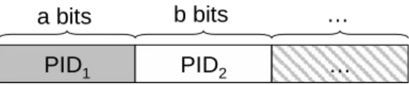
To perform HPID mechanism, we have to configure an HPID format in the beginning. First of all, we partition the HPID format into several segments and choose some PID mechanisms for each segment based on network characteristics. Figure 3-1 is an illus-tration of HPID format, and it represents that there are two or more segments partitioned.
Segment 1 is a-bit and uses mechanism PID1, segment 2 is b-bit and uses mechanism
PID2, etc. In order to explain our mechanism more clearly, we will take a scenario as an
example in the following introduction.
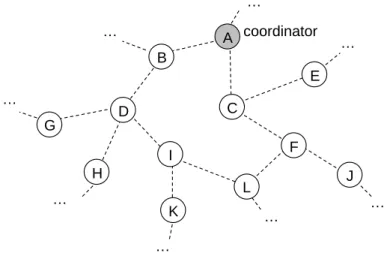
K J L G H I D F B E A … … … … … … … C … coordinator
Figure 3-2 Part of the distribution of the sensors.
Consider a scenario that we want to averagely distribute hundreds of sensors in a narrow area to control temperature of soil. Furthermore, each sensor should have a unique identity to recognize each other for sending data. Figure 3-2 illustrates the part of sensor distribution, and node A is a coordinator in the sensor network. Sensor devices have limited capabilities, such as memory and power. Therefore, the conventional ta-ble-driven mechanisms which need extensive routing table are not useful in this condi-tion. Conversely, we perform HPID mechanism to allocate identity for a sensor and configure an HPID format as follows.
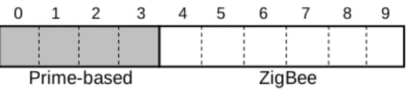
0 1 2 3 4 5 6 7 8 9
Prime-based ZigBee
Figure 3-3. Configuration of the HPID format.
As the scenario described, we would configure the HPID format as Figure 3-3, and identity length is 10-bit for hundreds of sensors. Due to the network characteristics we partition the format into two segments. The first segment is 4-bit using the Prime DHCP scheme with sub-identity range from 0 to 15. The second segment is 6-bit using the Zig-Bee mechanism with sub-identity range from 0 to 63. Because sensors are distributed in a narrow area, the tree structure should be flexible enough to extend the control range. Therefore, the Prime DHCP scheme is chosen for the first segment. Besides, the sub-tree structure should be balance for the average sensor distribution, and therefore we choose the ZigBee mechanism in the second segment. The parameters and Cskip values of the ZigBee mechanism are shown as Table 1.
Table 1. Parameters and Cskip values at each depth for ZigBee mechanism.
Parameters nwkMaxRouter 4 nwkMaxChild 4 nwkMaxDepth 3 Depth, d Cskip(d) 0 21 1 5 2 1 3 0
3.2
HPID Assignment Mechanism
HPID assignment mechanism is a distributed mechanism, and each entity can assign an HPID by operating independently. Later, we will introduce generation and assignment of HPID in two approaches, “forward HPID” and “backward HPID”.
3.2.1 Forward HPID Approach
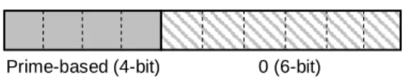
Prime-based (4-bit) 0 (6-bit)
Figure 3-4 Forward HPID of the 1st type.
Prime-based (4-bit) ZigBee (6-bit)
Figure 3-5 Forward HPID of the 2nd type.
Generation and assignment of forward HPID are started form the coordinator, node A in Figure 3-2. In the beginning, node A would produce an identity for itself. While other
node attaches to the coordinator, it will process mechanism PID1 (the Prime DHCP
scheme) to generate a forward HPID of the 1st type as form (a. 0) shown in Figure 3-4.
Among (a. 0), the former code, a, is 4-bit and produced by the mechanism PID1, and the
latter code is 6-bit with all zeros. Then node A will assign identities to the attached
nodes, such as node B and C. While identities of the 1st type have been assigned, node A
would generate an only one forward-HPID of the 2nd type as form (a. b) shown in
Figure 3-5. In (a. b), the former code, a, is the same as node A’s former code. The latter
code, b, is a 6-bit non-zero number and produced by mechanism PID2 (the ZigBee
mechanism) initially. Notice that b of the 2nd type’s identity (a. b) cannot be zero or
identity (a. 0) will be duplicated.
While a node has been assigned an identity of the 1st type, it could assign identities
to others as node A does. However, if a node is assigned an identity of the 2nd type, it
could only generate the 2nd type’s identities. The former code of the generated identity is
inherited from the node, and the latter code is produced by the mechanism PID2.
Notice that all of the produced codes should be up bounded by the identity space or within the limited restrictions. Say, the former codes must be within 15 and the latter
codes must be within 63. (1. 0) K (4. 2) Cskip = 5 J 23 (4. 23) Cskip = 5 L (15. 1) Cskip = 21 1 2 (8. 0) G H 2 3 (12. 0) I 1 (4. 1) Cskip = 21 D E F 2 3 5 (4. 0) (9. 0) (15. 0) B C 2 3 (2. 0) (3. 0) A … … … … … … … …
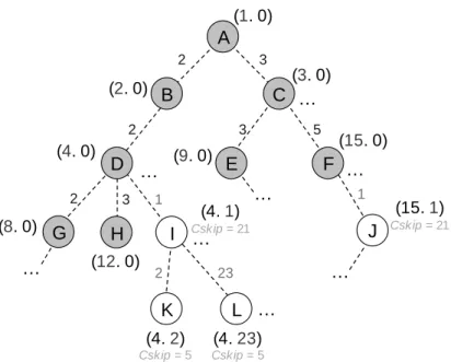
Figure 3-6 The forward-HPIDs allocation tree.
Figure 3-6 illustrates the identities allocation tree. Node A (1. 0) is the coordinator and its former code, 1, is the initial number produced by the Prime DHCP scheme.
Iden-tities of node B ~ H are the 1st type as well as node A, and the former codes of each are
produced via the Prime DHCP scheme by their parents. Take node F (15. 0) for example, the former code, 15, is produced form node C (3. 0). Because the former code 3*3 has been assigned to node E (9. 0), node C produces a sequential code 3*5 for node F. We call that node A ~ H are nodes on a sub-tree yielded by the Prime DHCP scheme, and node A is the root of the sub-tree.
Node I ~ L have identities of the 2nd type with the invariant former codes to their
parents, and the latter codes are produced via the ZigBee mechanism by their parents.
Take node I (4. 1) for instance, node D (4. 0) assigns a 2nd type’s identity to it because
all of the 1st type’s identities have been assigned. Therefore, the former code of node I, 4,
is inherited from its parent, and the latter code, 1, is the initial number produced by the ZigBee mechanism. The latter codes of node I’s children are also produced via the Zig-Bee mechanism. We call that node I, K, and L are nodes on a sub-tree yielded by the
ZigBee mechanism, and node I is the root of the sub-tree. Notice that the latter code of node I and J cannot be zero, otherwise the identity (4. 0) and (15. 0) would be dupli-cated.
However, with this approach, a problem and the related phenomenon must be con-sidered.
Leak of Identities
While HPID format has more than two segments, some identities will never be generated, and we call this problem “leak of identities”. For example, consider that an HPID format is partitioned into three segments and a root node has an identity as form (a. 0. 0) initially. Then the root node will generate identities as form (a. b. 0) to its chil-dren, but b must not be zero to avoid duplicate identities. Similarly, a node with identity as form (a. b. 0) will generate identities as form (a. b. c) with non-zero c. Therefore, identities with form (a, 0, c) will never be generated. This problem appears more sig-nificant while the number of partitioned segments increasing.
Unnatural Assignment
Besides, in Figure 3-6, we also observe that node L gets an identity form node I eventually although it can communicate with both node F and I physically. It is because node F has assigned the only one identity to node J. We call this phenomenon that a node can assign only one identity an “unnatural assignment” phenomenon. Such phe-nomenon always occurs in the leaf nodes of a sub-tree yielded by a certain mechanism. For example, node A ~ F are nodes on a sub-tree yielded by the Prime DHCP scheme, and node H and F are leaf nodes.
In order to eliminate the problem and the phenomenon, we propose another ap-proach in the next section.
3.2.2 Backward-HPID Approach with Modification
BN = 4
Prime-based (4-bit) 0 (6-bit)
Figure 3-7 Backward-HPID of the 1st type.
The main distinctions of backward and forward HPID approaches are the form of the 1st
type’s identities and the identities assignment method of the leaf nodes. In Figure 3-7,
the 1st type’s form of the backward-HPID is (0. a) with the all-zero 6-bit former code
and the latter code, a, which is 4-bit and produced via the mechanism PID1 (the Prime
DHCP scheme). The 2nd type’s form is (a. b) which is the same as the forward HPID.
The former code, a, is inherited from its parent’s code a. In other wards, the former code is the same as the latter code or the former code of its parent’s identity if its parent has the identity with the form (0. a) or (a. b) respectively. While the latter code, b, is 6-bit
long and produced via the mechanism PID2 (the ZigBee mechanism) by its parent.
Notice that the coordinator‘s identity cannot be zero, otherwise it will cause the duplicate identities. While the code b in the form (a. b) is zero-allowed, and the problem about leak of identities could be solved here.
(0. 1) BN = 0 K (4. 1) Cskip = 5 BN = 10 L 1 (15. 1) Cskip = 5 BN = 10 J (15. 22) Cskip = 5 BN = 10 22 1 (0. 8) BN = 4 G H 2 3 (0. 12) BN = 4 I 0 (4. 0) Cskip = 21 BN = 10 D E F 2 3 5 (0. 4) BN = 4 (0. 9) BN = 4 (0. 15) BN = 4 Cskip = 21 B C 2 3 (0. 2) BN = 4 (0. 3) BN = 4 A … … … … … … …
Figure 3-8 illustrates the backward-HPIDs allocation tree which is similar to the
forward HPID approach except the 1st type’s identities and the modified behaviors of
the leaf nodes, such as node F and H. In order to eliminate the unnatural assignment phenomenon, we let the leaf node takes the role as its only one child in the forward HPID approach. Take node F for example, instead of assigning the identity (15. 0) to its child, it takes the role as the node with identity (15. 0) and can assigns more than one identities via the ZigBee mechanism. In other words, the identity (15. 0) is reserved and never be assigned. Therefore, the modified behaviors of the leaf nodes could eliminate the phenomenon of the unnatural assignment phenomenon.
Besides, BN (Bit Number) used for routing procedure represents the length of the meaningful code, including the inherited and produced code. Learning BN’s value of each HPID costs no additional messages but just through computing the HPID directly.
Say, the 1st type’s identity must be less than 16 and the meaningful code is the last 4-bit
produced code, so the BN is equal to 4. Similarly, BN of the 2nd type’s identity is equal
to 10 because of the first 4-bit inherited code and the last 6-bit produced code.
3.3
HPID Routing Mechanism
The HPID routing procedure is performed through computing the HPIDs directly, so it is not necessary to lookup the extensive routing table and fasts the routing latency. Next, we will continue the scenario and introduce the routing mechanism via the backward HPID approach with modification. The routing procedure for the forward HPID ap-proach is trivial and similar to the backward HPID apap-proach, thus we take the backward HPID approach as an example to describe the routing mechanism.
If (RN_BN = D_BN) { if (RN_ID = D_ID)
RN is D;
else if (RN_Former_ID = D_Former_ID) { if (RN_BN = a)
run the routing mechanism of PID_1; else
run the routing mechanism of PID_2; } else {
send to P; }
} else if (RN_BN < D_BN) { shift D_ID right b bits;
if (RN_Latter_ID = D_Shifted_Latter_ID) run the routing mechanism of PID_2; else
run the routing mechanism of PID_1; } else {
send to P;
} • RN – the receiving node• D – the destination node • P – the parent node of RN (1)
(2)
(3)
To perform the routing procedure, the receiving node must to compute the HPIDs of the destination and itself when a node receives packets. The receiving node compares the BNs and conforms the following rules.
(1) If the BN of the receiving node is equal to the destination’s, then compare the former code of the HPIDs.
(i) If the former codes are different, then the receiving node sends the packets to its parent directly.
(ii) Otherwise, compare the latter codes of both.
a. If the latter codes are different, then the receiving node performs the
routing mechanism corresponding to the latter code. (Namely, if both
nodes’ HPIDs are the 1st type, then perform the mechanism PID1.
Otherwise, perform the mechanism PID2.)
b. Otherwise, the receiving node is the destination.
(2) If the BN of the receiving node is less than the destination’s, then shift the HPID of the destination right k bits to get the shifted HPID, where k is equal to
receiving node’s BN minus destination’s BN. Compare the latter code of the receiving node and the shifted HPID.
(i) If the latter codes are the same, then the receiving node performs the next
routing mechanism corresponding to its latter code (the mechanism PID2).
(ii) Otherwise, the receiving node performs the routing mechanism
corre-sponding to its latter code (the mechanism PID1).
(3) If the BN of the receiving node is larger than the destination’s, then the receiv-ing node sends the packets to its parent directly.
K (4.1) BN = 10 (0.1) BN = 4 (0.8) BN = 4 G H L (0.12) BN = 4 (15.1) BN = 10 I (4.0) BN = 10 J (15.22) BN = 10 D E F (0.4) BN = 4 BN = 4(0.9) (0.15) BN = 4 B C (0.2) BN = 4 (0.3) BN = 4 A a. b. c. d. e. f. g. … … … … … … … … (a) 22 15 1 4 K L (c) 0 4 22 15 0 15 D L L’ (g) 0 15 F 0 15 22 15 L F’
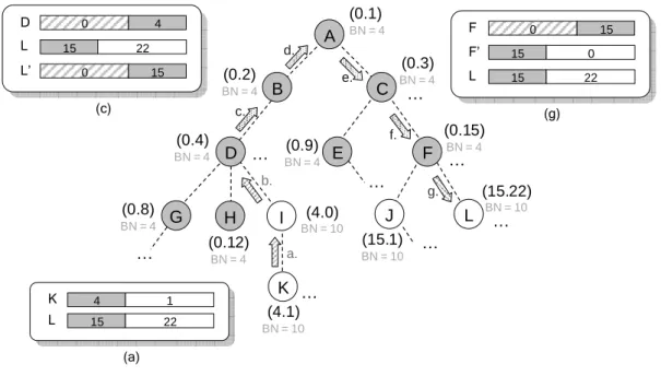
Figure 3-9 The routing procedure via the backward-HPID.
Figure 3-9 illustrates the routing procedure from node K (source) to node L (desti-nation). In (a), node K compares the HPIDs of itself and node L, and sends the packet to its parent (node I) directly because the former codes are different. Node I sends the packet to node D in (b) similar to (a). When node D receives the packet, it shifts the HPID of node L right 6 bits as L’ because D’s BN is less than L’s SN. Node D forwards the packet via the routing mechanism of the Prime DHCP scheme for the different latter codes of itself and L’, as well as (d), (e) and (f). Finally node F receives the packet and
sends to node L which is the destination via the routing mechanism of the ZigBee mechanism for the dual role as node (15. 0). Finally, the routing procedure is finished.
Chapter 4
Discussions of the HPID Mechanism
We have proposed the HPID assignment mechanism with two approaches, one is for-ward and the other is backfor-ward. Now, we would take the problems induced by each into consideration and process the quantitative analysis.
4.1
Forward Assignment
4.1.1 Leak of Identities
2a +
2a∙(2b -1) +
2a∙(2b -1) ∙(2c -1)
a-bit b-bit c-bit
2a∙(2c -1) ID space Leak of ID C 0 A 0 0 A 0 B A C B A
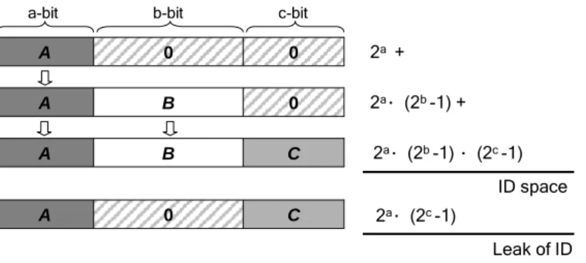
Figure 4-1 Identities leaking of forward assignment on three segments.
The forward HPID assignment is intuitive and simple, but it has a problem about “leak of identities” while there are more than two partitions. Figure 4-1 illustrates the situa-tion when the format is partisitua-tioned into three segments with a, b and c bits respectively.
Here, there are three types of identities, (A. 0. 0), (A. B. 0) and (A. B. C). The 2nd type’s
identities, (A. B. 0), inherit the former code of the 1st type’s identities, (A. 0. 0). In order not to produce the duplicate identities, the middle code B should not be zero. Similarly,
the latter code C of the 3rd type’s identities, (A. B. C), would not be zero either.
There-fore, the identities as form (A. 0. C) will never be generated and the amount of those leaking identities is 2a.(2c
as the number of segments increasing.
4.1.2 Quantitative Analysis
ID-length = 16 bits 0 10000 20000 30000 40000 50000 60000 2 3 4 5 6 7 8 Number of segments L eak o f id en ti ti es F. worst F. average F. bestFigure 4-2 Identities leaking of forward assignment.
The following equation calculates the number of leaking identities when there are k
par-titions, where ni represents the length of segment i.
(
2 1)
(
2 1)
, 2 2 2 1 2 2 1 ≥ ⎟⎟ ⎠ ⎞ ⎜⎜ ⎝ ⎛ − ⋅ − ⋅∑ Π
− = + + = + k k i n n n i j n j i L k (3)Figure 4-2 shows the effect of identities leaking on the different number of seg-ments for a 16-bit long identity. This figure indicates the worst, average and best cases of identity leaking among the entire HPID formats and assumes that the length of each segment is at least 2-bit long. We observe that no leaking identities there are while the format is partitioned into only two segments, but the number of leaking identities rises obviously as the number of segments increasing. When there are 8 segments, the num-ber of leaking identities is up to 52416 which is almost 80% of the whole identity space. This result also tells us that the forward assignment is not impracticable as the HPID format would be partitioned into many segments.
4.2
Backward Assignment
4.2.1 Leak of Identities
In order to reduce the effect of identities leaking, we propose the HPID assignment with the other direction, called backward HPID assignment. However, the backward assign-ment can not avoid the leak of identity for all HPID formats. In other words, the back-ward assignment can prevent the leak of identity just while the length of each segment is the same. But if the length of the first segment is shorter than the others’, the problem of identities leaking still occurs. The issue about the longer length of the first segment will be discussed later in the next section. Unlike the forward assignment, the backward assignment would have leaking identities for the format with two segments while the length of the first segment is less than the second one’s.
b – a B A 0 ≠ 0 … B A 0 A a < b,A≠0 2a– 1 + (2a– 1) ∙2b ID space (2b-a – 1) ∙2a 2b- 2a+ 1 Leak of ID a-bit b-bit 2nd 1st
Figure 4-3 Identities leaking of backward assignment on two segments.
An example of identities leaking for two segments is shown as Figure 4-3. In this
example, there are two types of identities, (0. A) and (A. B). Since the 1st type’s latter
code, A, cannot be zero, the identity “0” will never be used and cause one leaking iden-tity. Besides, the identities with the first a-bit zero code and next (b-a)-bit non-zero code
will never be generated either and the number is 2b - 2a. Thus, the total amount of those
4.2.2 Duplication of Identities
A 0 B A a-bit b-bit B A 0 ≠ 0 a – b 2a– 1 + (2a– 1) ∙2b ID space (2a-b – 1) ∙2b 2a– 2b Duplication of ID a > b,A≠0 Leak of ID: 1 2nd 1stFigure 4-4 Identities duplication of backward assignment on two segments.
However, if the length of the first segment is longer than any other’s, the identities du-plication will occurs, which is not allowed. An example of identities dudu-plication for two segments is shown as Figure 4-4. Similar to the example of Figure 4-3, there are two types of identities, (0. A) and (A. B). Since the length of the first segment is longer then the second one’s, the identities with the first a-bit zero code and next (b-a)-bit non-zero code will be generated twice. But such duplication would not be permitted for the most network environment, so the first segment’s length must not exceed the others’.
In order to avoid duplication of identities, we would configure the length of the first segment shortest while executing the backward assignment. Furthermore, we ob-serve that the backward assignment indeed decreases the effect of identities leaking sig-nificantly while the number of partitioned segments increases from the mathematical derivation and simulation results.
4.2.3 Quantitative Analysis
ID-length = 16 bits 0 10000 20000 30000 40000 50000 60000 2 3 4 5 6 7 8 Number of partitions N um be r of le ak -ID B. worst B. average B. bestFigure 4-5 Identities leaking of backward assignment.
The following equation calculates the number of leaking identities when there are k
par-titions, where ni represents the length of segment i.
(
2 1)
2 , 2 1 2 1 1 1− ⋅ ≥ +∑
= ∑ − − = k k i n n n i j j i (4)Figure 4-5 shows the effect of identities leaking on the different number of seg-ments for a 16-bit long identity. This figure indicates the worst, average and best cases of identity leaking among the entire HPID formats and assumes the length of each ment is at least 2-bit long. We observe that in the best cases for each number of seg-ments there will be some HPID formats that make the number of leaking identities pretty low. In other aspect, the worst case happens when there are two segments and the number of leaking identities is 16381 which is 30% of the identity space. Comparing to 80% to the forward assignment, the backward assignment really reduces the effect of the problem about leak of identity.
4.3
Summary
a perfect solution. If the number of segments is three, the performance of both forward and backward assignment is about the same. But if the number of partitioned segments is more than three, the backward assignment would perform better than the other one generally.
However, in the most situations the slight leak of identity is acceptable since the number of identity space usually exceeds the number needed. This is also the reason why we adopt the backward assignment for the simulation and analysis latter. Besides, we still have to notice the problem of identities duplication from the backward assign-ment and completely avoid the duplication happening.
Chapter 5
Simulation and Analysis
Figure 5-1 An example of network topology for simulation.
The HPID mechanism integrates the different PID mechanisms and combines the fea-tures of them. Next, we would give an example for the simulation environment and de-scribe the process of our mechanism. We generate 100 nodes randomly in a 100×100 (square unit) area. The signal range of each node is 20 (unit), thus the node would have 10 neighbors in average. The network topology is shown as Figure 5-1 and the root node is marked as a square.
According to the above network topology, we would use 8-bit long identities to identity all the nodes. The HPID format is configured like that the first 4 bits are pro-duced via the Prime DHCP scheme while the last 4 bits are via the ZigBee mechanism (nwkMaxRouters = 2, nwkMaxChildren = 2, nwkMaxDepth = 9). The tree structure of the network is shown as Figure 5-2 after allocating all the identities of nodes via the backward HPID assignment mechanism with modification. All the nodes could get an identity eventually and the average failure probability to obtain an identity of each node is 0% which is better than the other two mechanisms. Furthermore, the failure probability also effects the identities utilization of the network directly.
100 nodes 0 0.1 0.2 0.3 0.4 0.5 0.6 0.7 7 8 9 10 11 1 ID Length (bits) Fa il u re Pr o b . 2 Prime ZigBee Hybrid
Figure 5-3 The failure probability on different identity lengths.
However, if the failure probability is high on certain length of identity, we may try to increase the length to improve the failure probability. In order to analysis the im-provement of the different mechanisms, we simulate the Prime DHCP scheme and the ZigBee mechanism to compare with ours the failure probability of 100 nodes on differ-ent iddiffer-entity lengths. In this simulation, the network environmdiffer-ent is the same as the above one except the root node which is set in the center of the network area. As the Figure 5-3 shows, the failure probability of each node goes down while the length of identity increasing. When the length is 8-bit long, our mechanism could make all the nodes have their unique identities and the failure probability is almost 0%.
probability is still high while the length is up to 12-bit long. While the ZigBee mecha-nism needs to increase the length to 11-bit long to make the failure probability drop to 0%. From the results we could observe that for the other two mechanisms the increasing of the length cannot reduce the failure probability efficiently. It also means that these two mechanisms cannot use the identity space efficiently even though raising the iden-tity length. Unfortunately, the increasing of the length is not desirable in some environ-ments and the sensor network is just a critical example. Because to increase the length not only adds the data size but also make the overhead higher while computing the iden-tities to find the routing path. The problems induced by the increased length also con-sume more power to the sensor devices.
By the way, when the length is 7-bit long, our mechanism is a little worse than the ZigBee mechanism. This is because the length of the partitioned segment is too short and the problem of leak of identities will appear more significant corresponsively.
Next, we will compare our mechanism with the other two related mechanisms to analysis the failure probability to the number of nodes and identity length. The simula-tion environment is as follows. In a 100×100 (square unit) area, we will generate differ-ent number of nodes randomly and set the signal range dynamically to make each node have 10 neighbors in average. The root node is also set in the center of the network area and the length of the identity is configured different number of bits.
ID-length = 9 bits 0 0.1 0.2 0.3 0.4 0.5 0.6 0.7 0.8 0.9 50 100 150 200 250 300 350 400 450 500 Number of nodes Fa ilu re P ro b. Prime ZigBee Hybrid
Figure 5-4 Failure probability on various number of nodes (ID length = 9 bits)
ID-length = 10 bits 0 0.1 0.2 0.3 0.4 0.5 0.6 0.7 0.8 0.9 1 50 150 250 350 450 550 650 750 850 950 Number of nodes F ai lur e P rob. Prime ZigBee Hybrid
Figure 5-5 Failure probability on various number of nodes (ID length = 10 bits)
ID-length = 16 bits 0 0.1 0.2 0.3 0.4 0.5 0.6 0.7 0.8 0.9 50 150 250 350 450 550 650 750 850 950 Number of nodes F ailu re P ro Prime ZigBee Hybrid
Figure 5-6 Failure probability on various number of nodes (ID length = 16 bits)
Figure 5-4 , Figure 5-5 and Figure 5-6 illustrate the failure probability on the in-creasing number of nodes in 9-bit , 10-bit and 16-bit long identities respectively. In
Figure 5-4 we observe that the failure probability of the Prime DHCP scheme rises badly, and this curve is induced by the skew tree structure which is not applicable in the most network topologies. Although the curve of ZigBee mechanism seems better than the Prime DHCP scheme, it still increases obviously since the low flexibility of topol-ogy induced by the network restrictions. While our mechanism combines the benefits of different mechanisms and does the best job. In a saturated condition where the number of nodes is up to 500, we can also bound the failure probability under 40%. The simula-tion in Figure 5-5 also tells us the similar results mensimula-tioned above. In Figure 5-6, when there are 1000 nodes acquiring for identities among the 65536 identities, the other two mechanisms perform poorly, while our mechanism could still use the identity space ef-ficiently and the failure probability is less than 6%. From the above results, our mecha-nism indeed decreases the failure probability of each node and also improves the identi-ties utilization.
The HPID mechanism 0 0.1 0.2 0.3 0.4 0.5 0.6 50 150 250 350 450 550 650 750 850 950 Number of nodes F ai lur e P rob. 10-bit 11-bit 12-bit 16-bit
The Prime DHCP saheme 0 0.1 0.2 0.3 0.4 0.5 0.6 0.7 0.8 0.9 1 50 150 250 350 450 550 650 750 850 950 Number of nodes F ai lu re P ro b. 10-bit 11-bit 12-bit 16-bit
Figure 5-8 Failure probability on various identity lengths for Prime scheme.
The ZigBee mechanism 0 0.1 0.2 0.3 0.4 0.5 0.6 0.7 0.8 0.9 50 150 250 350 450 550 650 750 850 950 Number of nodes F ai lur e P rob. 10-bit 11-bit 12-bit 16-bit
Figure 5-9 Failure probability on various identity lengths for ZigBee mechanism.
Performance of HPID mechanism on the different lengths is shown as Figure 5-7. As the length of identity increasing, the failure probability is improved significantly. But Prime DHCP scheme and ZigBee mechanism could only enhance the failure probability lightly as shown in Figure 5-8 and Figure 5-9. Besides, the performance of out mecha-nism is also outstanding and these simulation results prove again that out mechamecha-nism could use the identity space more efficiently.
Chapter 6
Conclusions and Future Works
We have proposed a hybrid path-aware identity assignment mechanism to integrate the different path-aware identity assignment mechanisms. Our mechanism not only com-bines the benefits of the others but also improve the identities utilization significantly. Besides, we also propose a hybrid routing mechanism to perform the routing procedure with the HPIDs. Therefore, the routing path could be figured out by computing to the HPIDs directly and no extensive routing table is needed anymore. Our mechanism could not only enhance the performance of routing but also omit the additional messages for table maintenance. Although our hybrid mechanism may increase some computations of devices, the messages omitted could save more power, however. Nowadays the power saving is a very important issue to many network environments. Furthermore, the simu-lation results also reveal that our mechanism could decrease the failure probability for a node to obtain a unique HPID, which will improve the identities utilization directly. Therefore, we could shorten the length of identities due to the high utilization and the data and computing overhead are both decreased which are also helpful for power sav-ing.
However, there are several types of identities produced by our mechanism accord-ing to the number of partitions of the HPID format. We have provided the forward and backward assignment mechanisms and also discussed their features. Besides, the policy to assign the different types’ identities can be arranged for the network requirements and features. For example, if a network is composed of the backbone nodes and non-backbone nodes, we can select two PID mechanisms for the HPID format base on the features of the two kinds of nodes respectively. Then the nodes of each kind obtain
their identities of the different types. In other words, the HPID assignment policy could be adjusted dynamically through the different requirements. Therefore, each network can have its personalized and applicable HPID assignment mechanism and the identities utilization can be enhanced even more.
There are still many research issues of the proposed mechanism. For example, we would try to figure out the relationships between the HPID format and network features. Provide a method for the selection of PID mechanisms to achieve optimal identities utilization. Besides, we would also try to make our mechanism more robust for fault tolerance and mobility support. If some nodes are broken, the tree structure can heal by itself. If some nodes move, the routing procedure can be operated as usual.
Bibliography
[1] S. Biswas and R. Morris, “ExOR: Opportunistic Multi-Hop Routing for Wireless Networks,” ACM SIGCOMM, pp. 133-144, Philadelphia, USA, August 2005. [2] D. W. Bonn, “Automatically Identifying Subnetworks in a Network,” United States
Patent US6618755 B1, September 9, 2003.
[3] E. H. Callaway, Wireless Sensor Networks: Architecture and Protocols, Auerbach Publications, 2004.
[4] DARPA Internet Program Specification, et al., “IP Internet Protocol,” IETF RFC 791, September 1981.
[5] R. Droms, et al., “Dynamic Host Configuration Protocol,” RFC 2131, March 1997. [6] Y. Y. Hsu and C. C. Tseng, “Prime DHCP: A Prime Numbering Address Allocation
Mechanism for MANETs,” IEEE Communications Letters, vol. 9, no. 8, August 2005.
[7] IEEE 802.11 Working Group, “Amendment: ESS Mesh Networking,” IEEE Stan-dard Draft P802.11s/D1.0, November 2006.
[8] IEEE 802.16 Working Group, “Air Interface for Fixed Broadband Wireless Access Systems,” IEEE Standard 802.16-2004, October 2004.
[9] H. J. Ju and I. Rubin, “Backbone Topology Synthesis for Multi-Radio Meshed Wireless LANs,” IEEE INFOCOM 2006, pp. 1-12, Barcelona, Spain, April 2006. [10] M. Laubach, “Classical IP and ARP over ATM,” IETF RFC 1577, January 1994. [11] Y. B. Lin and A. C. Pang, Wireless and Mobile All-IP Networks, First Edition,
Wiley, November 2005.
[12] M. E. Lipman and R. L. Heyda, “Network Router Search Engine Using Com-pressed Tree Forwarding Table,” United States Patent US6192051 B1, February 20,
2001.
[13] C.S.R. Murthy and B.S. Manoj, Ad Hoc Wireless Networks: Architecture and Pro-tocols, Prentice Hall, 2004.
[14] C. Perkins, et al., “Ad Hoc On-demand Distance Vector (AODV) Routing,” IETF RFC 3561, July 2003.
[15] E. Rosen, et al., “Multiprotocol Label Switching Architecture,” IETF RFC 3031, January 2001.
[16] C. Schurgers, et al., “Distributed Assignment of Encoded MAC Addresses in Sen-sor Networks,” Symposium on Mobile Ad Hoc Networking and Computing (Mo-biHoc'01), pp. 295-298, Long Beach, CA, October 4-5, 2001.
[17] C. Schurgers, et al., “Distributed On-demand Address Assignment in Wireless Sen-sor Networks,” IEEE Transactions on Parallel and Distributed Systems, October 2002.
[18] Y. Sun and E. M. Belding-Royer, “A Study of Dynamic Addressing Techniques In Mobile Ad Hoc Networks,” Wireless Communications and Mobile Computing, vol. 4, no. 3, pp. 315–329, 2004.
[19] M. Thoppian and R. Prakash, “A Distributed Protocol for Dynamic Address As-signment in Mobile Ad Hoc Networks,” IEEE Transactions on Mobile Computing, January 2006.
[20] ZigBee Standards Organization, “ZigBee Document 053474r06, Version 1.0,” De-cember 14, 2004.