國 立 交 通 大 學
電控工程研究所
碩士論文
設計與實作適用於傳統紅外線家電之低功率
無線智慧型控制器
Design and Implementation of Low-Power Wireless Intelligent
Controller for Legacy IR Appliances
研 究 生: 鄭偉強
Student: Wee-Keong Tey
指導教授:黃育綸 博士
Advisor: Dr. Yu-Lun Huang
中華民國一百年九月
設計與實作適用於傳統紅外線家電之低功率無線智慧型控制器
Design and Implementation of Low-Power Wireless Intelligent Controller for
Legacy IR Appliances
研 究 生: 鄭偉強 Student: Wee-Keong Tey 指導教授:黃育綸 博士 Advisor: Dr. Yu-Lun Huang
國 立 交 通 大 學 電控工程研究所
碩士論文
A Thesis
Submitted to Institute of Electrical Control Engineering College of Electrical Engineering
National Chiao Tung University in partial Fulfill of the Requirements
for the Degree of Master
in
Institute of Electrical Control Engineering
September, 2011
Hsinchu, Taiwan, Republic of China 中華民國一百年九月
設計與實作適用於傳統紅外線家電之低
功率無線智慧型控制器
學生: 鄭偉強
指導教授:黃育綸 博士
國 立 交 通 大 學電控工程研究所(研究所)碩士班
摘
要
智慧型住宅(Smart Home)技術與寬頻網路的日漸普及,帶動了智慧型網路家電產品 的發展。 但是目前大多數人都仍然還在使用那些非網路的傳統家電設備(Legacy Home Appliances)。 其中有幾個關鍵的原因如產品價格、網路的互通性以及使用者習慣的問 題,使得智慧型網路家電設備一直沒有辦法被廣泛使用。 因此,配合家庭網路系統來 控制傳統家電設備的概念因應而生。 許多專家學者也開始針對傳統家電設備提出了各 種不同的控制方法和流程。 然而,這些針對傳統家電設備所提出的控制方法卻缺乏系 統化、全面性的控制程序。 因此,在這篇論文之中,我們引入網路分層的概念,提出 了一套控制傳統家電設備的三層網路架構。 在架構的最上層, 我們設計一個介面供使用 者控制和管理傳統家電。 而中間是屬於網路傳輸層,主要是使用一些通訊技術來接收 和傳送資料。 而最底層則定義實體的傳輸媒介處理控制訊號的學習及轉換。 我們的控 制對象鎖定為能接收紅外線訊號的傳統家電。 隨後,我們以無線電模組(TI CC2500)及 紅外線收發模組(IR Transceiver Module)做為系統中主要的資料傳輸接面,並實際佈置 一個簡單的住家場景,透過我們所提出的架構來管理與控制傳統家電設備。Design and Implementation of Low-Power Wireless
Intelligent Controller for Legacy IR Appliances
Student: Wee-Keong Tey
Advisor: Dr. Yu-Lun Huang
Institute of Electrical Control Engineering
National Chiao Tung University
Abstract
With the popularity of smart home and broadband networking technologies, more and more networked modern home appliances are researched, developed and promoted. But, the expensive cost and bad interoperability make modern intelligent devices a bad replacement for non-networked legacy home appliances. Hence, many diverse control methods and intelligent control flows are proposed to control legacy home appliances using the existing home networks. However, these methods are lack of a systematic control procedures, including device registra-tion, communication and signal conversion. In this research, we propose an architecture for controlling legacy home appliances by using 3-layer network model. The model consists of upper (users), middle (networking) and lower (devices) layers. The upper layer designs inter-faces for users to register and control legacy home appliances. In the middle layer, two or more networking technologies are hybrid to send and receive control commands from users. Then, methods to learning and converting signals are defined in the lower layers. In our system, only infra-rad (IR)-based legacy home appliances are installed in a home environment. After learning the IR signals of legacy appliance, users can control these devices via the user interfaces pro-vided in the upper layer. Then, we adopt RF modules (TI CC2500) and IR transceiver modules to forward commands between the users and the legacy home appliances.
誌謝
本論文能順利完成要感謝很多人的幫助,首先感謝指導教授黃育綸博士在這碩士 兩年多的時間裡,給予相當自由的研究空間,並認真和耐心地教導我,培養我正確的 研究方法,尤其是在任何事情的完整性、邏輯性等,讓我受益匪淺。 另外,還要感謝實驗室的同儕不僅在課業方面,也使我在這段兩年的研究生活中 逐漸成長茁壯。博班的學長姐蔡欣宜學姐以及陳柏廷學長,非常感謝兩位學長姐在論 文、口試以及計畫方面的幫助。另外感謝甄元斌學長、黃啟彥學長、吳嘉稘學長、王 雅萱學姐、吳思穎學姐、彭博群學長等;同屆的好友黃奕奇、許鴻生以及黃晉澤;還 有學弟妹們包括賴鈺婷、葉書宏、李勇叡、陳玟媗等人。另外要特別感謝和我一同從 電工進入電控所的同學黃錦銘,在我的研究方面給予我很多的幫助。實驗室的研究生 生活因為有了你們,變得更加多采多姿。 最後,感謝我的家人們這些年來在背後默默的支持及鼓勵。感謝父母總是在做決 定時給予我絕對的自由,讓我的求學生涯一路順遂,並期許自己在將來能更加精進。Contents
摘要 i
Abstract ii
誌謝 iii
Table of Contents iv
List of Figures vii
Chapter 1 Introduction 1
1.1 Definitions and Elements . . . 1
1.2 Challenges . . . 2
1.2.1 Technologies for Communications Network . . . 3
1.2.2 Challenges . . . 4
1.3 Existing Solutions . . . 5
1.4 Motivation . . . 5
1.5 Synopsis . . . 6
Chapter 2 Infra-Red Control 7 2.1 Infra-Red . . . 7
2.2 IR Remote Control . . . 8
2.3 Summary . . . 9
Chapter 3 Related Work 10 3.1 Web-based Remote Control . . . 10
3.3 Infra-Red Control in Wireless Network . . . 14
3.4 Summary . . . 16
Chapter 4 Proposed Architecture 18 4.1 System Components . . . 19
4.1.1 Home Gateway (HG) . . . 20
4.1.2 eZ-Red Devices . . . 21
4.1.3 Home Appliances (IR Appliances) . . . 21
4.2 Layers . . . 22
4.3 Registration Phases . . . 24
4.3.1 Grouping . . . 24
4.3.2 eZ-Red Installation (Middle Layer) . . . 25
4.3.3 IR Appliances Registration (Upper and Lower Layer) . . . 26
4.4 Control Phases . . . 27
4.4.1 Select Controlled Target (Upper Layer) . . . 27
4.4.2 Control Message Transmission (Middle Layer) . . . 28
4.4.3 IR Communication (Lower Layer) . . . 28
4.5 Summary . . . 29
Chapter 5 Implementation 31 5.1 Hardware . . . 31
5.1.1 Home Gateway (HG) . . . 31
5.1.2 eZ-Red Device . . . 33
5.1.3 Home Appliances (IR Applianes) . . . 34
5.2 Software . . . 35
5.2.1 Upper Layer . . . 35
5.3 Scenarios . . . 39 5.4 Discussion . . . 40 5.5 Summary . . . 42
Chapter 6 Conclusion 43
List of Figures
1.1 OSI model vs Smart Home Model . . . 3
2.1 Infra-Red Signal Modulated . . . 8
2.2 Typical frame structure for IR control signal . . . 9
3.1 A soft-controller for a legacy TV [13] . . . 11
3.2 Proposed architecture for adapting legacy appliances using web services 12 3.3 System configuration for Park's scheme . . . 14
3.4 Architecture of IR control in wireless network [15] . . . 15
3.5 Example to depicts detailed content and techniques . . . 17
4.1 System overview of proposed architecture . . . 18
4.2 Connection scheme among all components . . . 20
4.3 Schematic of Central Management Unit (CMU) . . . 21
4.4 Components with layers . . . 22
4.5 System design from the prespectives of layers . . . 23
4.6 eZ-Red installation process . . . 25
4.7 IR appliances registration . . . 26
4.8 Communication in upper layer . . . 27
4.9 Message transmission in middle layer . . . 28
4.10 IR signal translation in lower layer . . . 28
4.11 System overview . . . 30
5.1 Wireless network module . . . 32
5.2 eZ-Red device . . . 33
5.4 Block diagram of RPM6900 series IR receiver module [24] . . . 34
5.5 eZ-Red device . . . 35
5.6 Software implementation for each layer . . . 36
5.7 The architecture of SimpliciTI protocol, [25] . . . 37
5.8 Algorithm of AP-to-ED communication . . . 38
5.9 An example of receive signal . . . 39
5.10 Scenario . . . 40
Chapter 1
Introduction
A Smart home is also named as an intelligent home, home automation, electronic home (E-home), digital family, network home or intelligent building [1] [2] [3] [4]. Smart home, based on home automation, is implemented via simulating human needs. Exploiting advanced computing technologies, network communication and routing techniques, home appliances are systematically connected together. Comparing with traditional home environment, passive and stationary machines become automatic devices with intelligence providing all-purpose message exchanging functionality.
The goal of a smart home is to provide better life quality through a multimodal intelli-gent control system embedded in a home environment. Applications and services that a smart home provides are extensive, including home appliance automation, health care (home care) [5], home security [6], remote-controlled management and maintenance on home appliances, home energy management system [7]. However, this thesis focuses on home appliance automation. This chapter introduces the definition and elements of a smart home. We also discuss the new technologies and challenges for a smart home communication network.
1.1
Definitions and Elements
In Department of Trade and Industry (DTI) Smart Home Project, a smart home is defined as "a dwelling incorporating a communications network that connects the key electrical
appli-ances and services, and allows them to be remotely controlled, monitored or accessed." In the definition, "remotely" means both inside and outside the dwelling [8].
Mainly, a smart home consists of three major elements, including an internal network, a intelligent control system and a home automation system [2]. The internal network the basis of a smart home is a home networking system. Such a network, either wire or wireless, is in charge of communication of home appliances, and it can be power-line, bus-line or radio frequency. The intelligent control means the gateway, routing rule or protocol to manage the home network systems. The main purposes is to bridging different technologies within the home and providing access from the home to external services or from external systems to home. The home automation means those appliances within the houses are linked to the services and systems outside the home automatically to increased quality of life.
1.2
Challenges
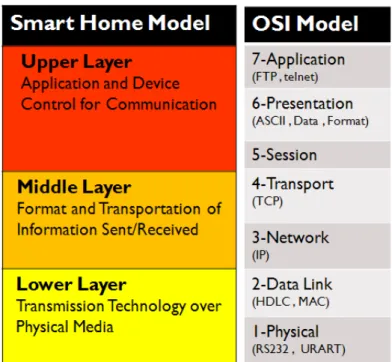
Building up a house smart means to install a high tech communications network in a house, which allows various systems and appliances communicate with each other. Comparing to the OSI model [9], the smart home communications network technologies can be classified into three layers, which is also called smart home model, show as Figure 1.1.
In a smart home model, the low layer represents physical communication technologies, such as Ethernet, RF, Infra Red (IR) and Bluetooth. The middle layer is responsible for packet processing and routing. The upper layer is devised for applications. User-end to device-end communication interfaces are realized at this layer.
Figure 1.1: OSI model vs Smart Home Model
1.2.1
Technologies for Communications Network
Lots of industrial standards designed for smart homes have been proposed. Some common technologies of communications network are developed by several familiar alliances, such as Digital Living Network Alliance (DLNA), ZigBee Alliance, UPnP Forum and Echonet.
These alliances include consumer electronics, mobile, PC corporations etc. They develop their own communication standards depending on their proprietary technologies and applica-tions. For example, standards made by DLNA(Digital Living Network Alliance) [10] focuses on multimedia entertainments. ZigBee Alliance [11] applies low-cost, low-power wireless tech-nologies (IEEE802.15.4) to home automations. UPnP(Universal Plug and Play) Forum [12] aims at making devices linked seamlessly and simplifies implementation of home networking systems.
1.2.2
Challenges
Accompanying with developments of the emerging communication technologies, designs of modern home appliances are gradually linked to home networking systems. These home appli-ances are usually called networked appliappli-ances. In generally, networked appliappli-ances are equipped with smart embedded devices, including a network interface, a processor and a storage device. The purpose is making networked appliances capable of executing application programs and services in home networking systems. Due to downsizing, prices reduction and energy-saving of embedded devices, all appliances networklized can be imagined in the future.
However, transition to networked appliances is an incremental and slow process. Most people still use non-networked legacy home appliances now. Several determinant factors make networked appliances not widely deployed. First of all, because networked home appliances are equipped with embedded devices, prices of these appliances are even higher than the legacy counterparts. Many manufacturers also consider their market value. If the market value is not appealing enough, the product will not be deployed. Hence, commercially available products are very rare.
Another determinant factor is the interoperability problem, the integration of networked appliances are limited especially in the multi-vendor environment. The key factor that a user keeps using original appliances is the user’s habits. Changing from legacy home appliances era to networked appliances era is not easy. Thus, many researchers start conducting researches and inventions on automatic control for legacy home appliances.
1.3
Existing Solutions
Recently, quite a few researches are conducted on control and management of legacy ap-pliances. For example, in 2006, M. Nakamura et al. designed a web based remote control [13]. They focus on designs at application layer. The overall architecture takes software as basis, so application programming interfaces (APIs) are defined for different platforms. The software modules design based on the API can be inter-operated in the manner of web services.. How-ever, we consider that data transfer at physical layer is incomplete. Another researches focus on control and management at middle and lower layers. For instance, in 2007, W. K. Park et al. de-signed a ZigBee based universal remote control [14], which replaces infra-red remote controller with ZigBee. In 2010, a utility model patent about using wireless virtual IP to make infra-red devices available in a wireless network system has been proposed [15]. The purpose of their design is to control infra-red home appliances over a wireless metwork. We consider that these researches and inventions on control and management of legacy home appliances are not intact systems.
1.4
Motivation
In a dwelling environment, most legacy home appliances are controlled and managed via corresponding remote controllers. Transmissions of most of these remote controllers are based on infra-Red (IR) signals. Therefore, we define legacy home appliances as home appliances which receive IR signals and do not have network interfaces.
In this thesis, we introduce layers notion to proposed architecture based on a three-layer smart home model (Figure 1.1) and propose corresponding control and management mecha-nisms in different layers. These mechamecha-nisms are integrated into an intact system. We consider
that designing a intelligent control system for home appliance. Compared to the previously mentioning model, such a model might be limited on legacy home appliances.
In our design, home gateway are installed at the upper layer to support user interfaces. At middle layer, wireless personal area network (WPAN) is used to support infra-red communi-cation, helping long distance transmission and obstacle bypassing to control legacy home ap-pliances. In the field of short-range wireless communication, especially the wireless remote control. Therefore, the lower layer we designed is equipped with infra-red transceiver modules, providing communication interfaces between our system and legacy home appliances. We ulti-mately realize the proposed architecture with the implementation of a wireless network module and a infra-red transceiver module, eZ-Red.
1.5
Synopsis
The remainder of this paper is organized as follows. Chapter 2 introduces the Infra-Red signal specification. Related works, which designed to solve legacy home appliances control problem, are described in chapter 3. Chapter 4 presents the proposed model and chapter 5 discusses our implementation in detail. Finally, conclusion summarizes our research in chapter 6.
Chapter 2
Infra-Red Control
Principles, characteristics and applications of infra-red are illustrated in this chapter first. Then, operation of infra-red remote control comes after. Finally, the way we use infra-red remote control signal is explained at the end of this chapter.
2.1
Infra-Red
Infra-Red (IR) is one of electromagnetic waves used in wireless communication technolo-gies. Its wavelength is between 0.76 lit um to 1 lit mm. This wavelength is out of visible spectrum, so IR belongs to invisible light. There are many IR applications and can be classi-fied into two categories, un-modulated IR signal and modulated IR signal [16]. Un-modulated IR signals are common used for temperature sensing. Modulated IR signals are normally used in wireless remote control and data transmission of home appliances or digital products. Our research focuses on modulated IR signals.
Modulated IR signals of home appliances are mainly used with wireless remote control. A remote controller is the typical example. Wireless remote control includes a transmitter and a receiver. Operating components are IR light-emitting diodes (IR led) and IR sensors. In next section, operating principles of transmitters and receivers in remote control are illustrated in detail.
2.2
IR Remote Control
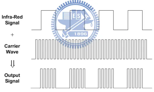
An IR remote control uses modulated IR signals. Transmitters and receivers operation as descripted as follows. First, transmitter-end emits infrared-ray emitted via IR led, and uses harmonic waves produced by oscillators as carrier waves to emit particular waves. In general, the frequency of the carrier waves is about 38 to 40kHz. This procedure is called IR modulation and shown in Figure 2.1.
At the receive-side, a receiver uses an IR sensor to receive emitted infrared-ray and eval-uate luminance of emitted infrared-ray to produce corresponding electric currents. Other post-processing like magnifying signals by operational amplifiers is carried out by gather information from IR signals.
Figure 2.1: Infra-Red Signal Modulated
Normal domestic remote control devices require multiple control commands, so coding on an IR signal is necessary. When coding, coding chips are used to produce digital waves and superimpose these digital waves on carrier waves. Then, IR led emits these combined waves. Coding chips produced by different manufacturers have different IR control protocols. For ex-ample, Philips RC-5 protocol, NEC protocols and so on [17] [18].
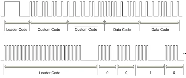
Figure 2.2: Typical frame structure for IR control signal
remote control signals are composed of leader code, custom code and data. Leader code indicates the start point of an IR signal. Custom code is used to represent manufacturer code. Data represents the pressed button on remote controller. These codes are defined by each manufacture alone. In other words, this frame structure is only for reference.
2.3
Summary
An IR remote control uses infrared-ray as its transmission media. IR has many merits like high noise-resistance, reliable message transmission, low-cost and low-power. Accompanied with these merits, IR is widely used in remote control of home appliances. However, devel-oped by various different manufactures, the format of IR remote control signal is difficult to be adopted into a smart home system. Besides, IR is limited by its light property. It cannot penetrate most of obstacles. Its track should be straight. These limitations put impact on the development of integrating legacy home appliances into a smart home. In next chapter, several researches on legacy home appliances control are stated in company with different pros and cons.
Chapter 3
Related Work
In this chapter, three related research related to home appliance control are discussed. The controlled subject is locked on the range of legacy home appliances. Web first take control and management methods on home appliances in the beginning [13]. Then, the design scheme of ZigBee based remote control is introduced [14]. Last one is a utility models patent, which merges infra-red control into wireless network [15].
3.1
Web-based Remote Control
In 2006, Nakamura et al. presented a framework to adapt the legacy home appliances with an IR remote control to an emerging home network system. Nakamura used the concept of service-oriented architecture (SOA) [13] [19] to improve programmable interoperability among multi-vendor legacy home appliances.
First, a traditional legacy home appliance control method, using PCs or handheld devices such as handy phones is adopted. Figure 3.1shows an example using traditional method to control a legacy TV. A user selects and executes a control command throught the user interface (UI). Then, the proprietary application sends the corresponding infra-red signal to the legacy TV through driver and the interface of the infra-red remote controller (denoted by IrRC) . The limi-tation of this method is that, the appliance and the application are tightly coupled. The same con-troller cannot be used directly for other appliances. Therefore, Nakamura et al. exploited SOA
Figure 3.1: A soft-controller for a legacy TV [13]
concept to implement multi-vendor appliances control in a home networking environment [20]. SOA is a system architecture that facilitates flexible integration of a distributed heterogeneous system. That is, all programs and contents are wrapped in services, and a standard interface is implemented to encapsulate inconsistencies.
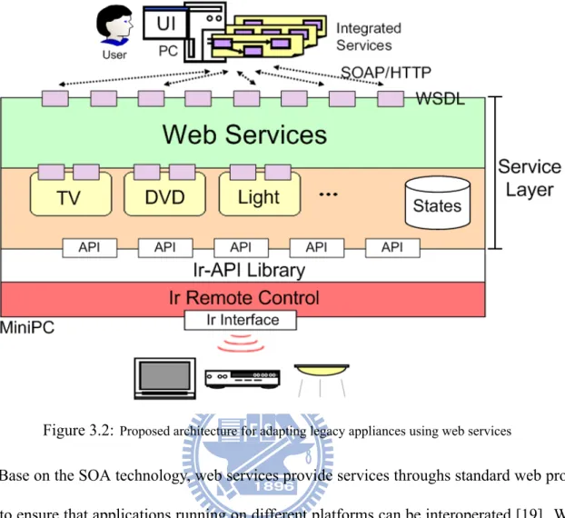
As shown in Figure 3.2, Nakamura develop a set of Ir-APIs that assist a mini PC to send infra-red signals to the legacy appliances. Then they aggregate the multiple Ir-API within self-contained service components, which achieve a logical feature independent of the appliance specific operations. For every service, components implemented at the service layer are strictly typed by a XML-based language, called web services description language (WSDL). Finally, the service components are exported to the home network system as a Web-API with web services. Thus, the legacy appliances can be used as distributed components in the network system. By combining these components, the user can assemble various integrated services. Furthermore, they also implemented the actual home network system with multi-vendor legacy appliances to verify their proposed framework.
Figure 3.2: Proposed architecture for adapting legacy appliances using web services
Base on the SOA technology, web services provide services throughs standard web proto-cols to ensure that applications running on different platforms can be interoperated [19]. With this characteristic, the framework proposed by Nakamura et al. extensively reduces interoper-ability problem at the upper layer. Also, the framework is applicable to wide range of types and vendors of the appliances. However, the limitation of Nakamura’s framework is the reliability of the lower layer (the physical channel between an IR remote control interface and the appliance). We consider the insufficiency comes from device combining the system and infra-red remote controller. Once the amount of appliances becomes much more, constructor should spend more cost on purchasing more mini PCs, as shown in Figure 3.2, ensuring accurate control. Another shortcoming is that, their user interfaces are not user-friendly. The author's web APIs are written in XML format, encapsulated using SOAP and transmitted by HTTP. If self-implementation is needed, users should understand XML format first. Also, the ability of programming is part of
requirements. These requirements are tough for normal users.
3.2
ZigBee based Remote Control
In 2007, Wan-Ki Park et al. proposed a novel ZigBee based universal remote control system to control and manage multiple IR-based legacy appliances. The scheme is based on IEEE802.15.4, especially ZigBee protocol [14].
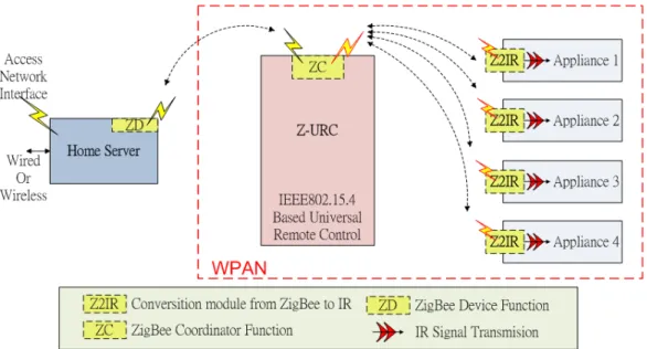
There is two types of main components used in this scheme. One is a universal remote control using Zigbee based wireless network technology, called Z-URC (ZigBee based Universal Remote Control). All control commands used to control the multiple legacy home appliances are generated by this single Z-URC unit. Z-URC operates as a ZigBee coordinator in the scheme. Another component is the conversion module, called Z2IR (ZigBee to Infra-Red), converting IR and ZigBee signals. A Z2IR used to convert a control message transferred through the ZigBee wireless network into IR typed signal. The module is attached on each target appliance. Z2IR modules operate as a ZigBee devices in this scheme. The overall system configuration for Park's scheme is shown in Figure 3.3. The ZigBee WPAN (wireless personal area network) shown in the figure is the communication network between a Z-URC and Z2IR modules. It is based on IEEE 802.15.4 ZigBee wireless networking technology.
The list of appliances to be controlled by a Z-URC is dynamically reconfigured. It depends on the location of a user holding the Z-URC unit. Each Z2IR module can be configured with a product identifier and a vendor identifier for his target appliances. Z-URC uses these two iden-tifiers, sent by Z2IR modules within the signal range, to reconstruct the list of appliances. In this manner, the system can control and manage multiple IR-based home appliances more effi-ciently and the limitations on unidirectional transmission of IR signals is also eliminated. Using
Figure 3.3:System configuration for Park's scheme
ZigBee WPAN networks, information transmitted between appliances becomes bi-directional. As Figure 3.3shows, Park's set a home server. The functionality of the server is linking Z-URC to internet in order to gather control profiles and provide services. However, the actual connection mechanism between a Z-URC and a home server is un-mentioned. We consider that the upper layer is not complete enough. Besides, every home appliance is equipped with a Z2IR module, which makes cost high. An ideal smart home control system should not add any extra hardware to control legacy home appliances. Otherwise, the original control system is useless.
3.3
Infra-Red Control in Wireless Network
In 2010, a new utility patent equips an infra-red control device with wireless virtual IP has been proposed by R.S. Tang. (R.O.C patent: M 373076) [15]. The main function of this util-ity patent is exploiting network communication on infra-red remote control devices controlling home appliances.
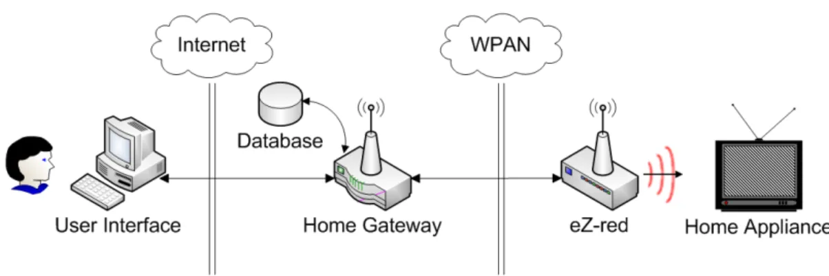
Figure 3.4: Architecture of IR control in wireless network [15]
consists of three units, including the host, the server and IR remote control device. The host is linked using LAN (local area network) and controls at least one home appliance. The host can be a PC or a mobile phone.
The server has a wireless network and RS485 interfaces. This wireless network interface is used to connect the previously mentioned LAN. The network protocol can be Bluetooth, mi-crowave or infra-red. The RS485 interface connects the IR remote control device. The server can transmit an IR signal via this IR remote control device, controlling home appliances. There-fore, a user links the LAN using a device called the host to connect to the server, and then he/ she can manage home appliances via this server. The server receives user's commands, transfers to IR signals and transmits them to assigned home appliances via RS485 connected to the IR remote control device.
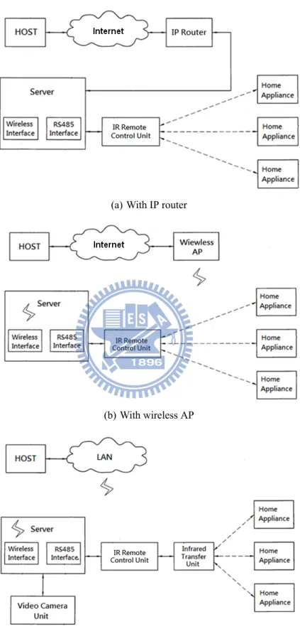
Tang's depicts detailed content and techniques using several examples in Figure 3.5. In Figure 3.5(a) and Figure 3.5(b), the system can be implemented with IP Router or wireless AP, which provides a virtual IP or fixed IP for the server connecting to the internet. Therefore, users can link to the server via the internet, remotely controlling home appliances. In Figure 3.5
(c), when the IR signal between IR remote control devices and home appliances are blocked, an infra-red transfer unit can be added to enhance transmission distance and solve the signal-blocked problem. In addition, a video camera unit, like a surveillance camera, can be added into the system. Users at the outside or in the different room realize that operations of home appliances are correct.
The primary characteristic of this new utility patent is that, the server links to the internet via a selectable virtual IP. Remotely control home appliances from outside can be achieved using any linked PC. Also, using virtual IPs can avoid network attack by hackers, who elevate security. From system aspect, this patent has complete designs from upper layer to lower layer. However, the author only provide system architecture scheme and does not attach actual design and implementation contents.
3.4
Summary
We introduce three related researches on controlling legacy home appliances in this chapter and discuss problems from the aspect of smart home three-layer model. Although the web based remote control focuses on web services of upper layer, we consider that their framework would be more complete if they considered designs of lower layer. The ZigBee based remote control method dexterously exploits wireless characteristics of ZigBee, but their designs on upper layer are not enough. On the other hand, Tang's patent fits three-layer smart home model most, it is a new utility patent only, not an actual implementation.
We consider the three-layer smart home model is needed. For this reason, we intend to design an architecture supports the three-layer smart home model in controlling and managing legacy home appliances. We detail our designs in the next chapter.
(a) With IP router
(b) With wireless AP
(c) With IR transfer unit and video camera unit
Chapter 4
Proposed Architecture
This chapter discusses the proposed architecture to manipulate multiple legacy home appli-ances (IR appliappli-ances) in a smart home system. Our design is based on three-layer smart home model. Please refer to Figure 1.1. We design respective control mechanism in each layer and integrate them into an intact architecture, which makes control on home appliances more effi-ciently.
Figure 4.1 is the system overview of the proposed architecture. Due to the control limita-tions on distances and orientalimita-tions of IR controlled home appliances, we add a compact device with wireless network modules and IR transceiver modules, called eZ-Red. The reason we choose wireless network as transmission method is not only to remove IR control limitations, but also benefit from many merits wireless network possessed like low-cost, low-power and high reliability. Thus, wireless network is appropriate to be used in automatic control and many sim-ilar wireless technologies like ZigBee, SimpliciTI can be chosen [21]. In addition, the eZ-Red we adopted is a one-to-many control device. Many home appliances can be controlled using an eZ-Red device.
In this chapter, we introduce system components first, and then import layer notion to illus-trate the design of system flow. Next, we explain the registration procedure and system control flow. Finally, illustration puts on IR communication.
4.1
System Components
First, we present system in a simplified manner, and then introduce goal and features of every component in detail.
According to our design at least one user interface (UI) is needed to let user link to home gateway (HG). Also, at least one eZ-Red device should be connected to HG and communicate with HG via wireless network. Therefore, HG and eZ-Red require wireless network module. Next, IR signal is used in communication between eZ-Red devices and home appliances. Fig-ure 4.2 shows the connection scheme among all components.
Figure 4.2: Connection scheme among all components
4.1.1
Home Gateway (HG)
The key component in whole system is HG. We design HG as central management unit (CMU), a bridge which connects the outer network, the Internet, and the inner network, wireless personal area network (WPAN). Thus, HG connects Ethernet, WPAN and the database (DB) for data recording. For the sake of functionality, CMU offers two primary functions, user interface and data processing.
User Interface (UI)
User interface (UI) builds connections between users and devices to let users communicate with the system. Thus, UI is the bridge for communication between users and the system. Data Processing
Data processing stands for control message processing. Here, control message includes control code, appliance identifier (ID) of home appliances and address of eZ-Red device.
Previous mentioned functions are for efficient management on entire system. However, information produced by these functions becomes huge when appliances amount is increasing.
Thus, we design a database (DB) to access related information. Figure4.3 is the schematic of CMU. Arrows indicate communication relationships between components.
Figure 4.3: Schematic of Central Management Unit (CMU)
4.1.2
eZ-Red Devices
In Figure 4.2, eZ-Red links HG and home appliances. Thus, eZ-Red needs two interfaces at the same time, wireless network module and IR transceiver module. The primary function of eZ-Red is transforming data format for communication. Because our controlled subjects are IR typed home appliances, transmission and receiving of IR signal are essential. We make use of the merit of wireless network to break the transmission restriction on distance and orientation of IR signal. In this manner, we significantly promote the system usability.
4.1.3
Home Appliances (IR Appliances)
In domestic environment, most of legacy home appliances are controlled and managed by different remote controllers, usually IR based ones. Proposed system is mainly for IR appliances, so we need interfaces for them. Considering the differences on the format of IR control signals produced by different manufactures, these IR control signals, are recorded directly and stored to database (DB). When demanding to use that appliance, system recalls those IR control signals
from database and emits them via our IR transceivers module. Consequently, there is no need to know the detailed content of control signals.
After introducing system components, in next section, we will import the layer notion and illustrate the design of system flow.
4.2
Layers
The purpose of importing layer notion is to equip more complete control mechanisms to our system. Referring to three-layer smart home model, we design respective control mechanism in each layer. From lower layer to upper layer, we design appropriate mechanism based on their applicability and related control techniques.
Figure 4.4:Components with layers
The design concept of lower layer is based on physical layer of OSI model. Please refer to Figure 1.1. The primary function is to construct bit stream communication among adjacent nodes. Because our controlled subject is locked on IR-only home appliances, bit stream com-posed of "0" and "1" is used and transmitted via IR signals.
The design concept of middle layer is based on network layer and transport layer of OSI model. Please refer to Figure 1.1. The primary function is message exchange and data
com-munication in the network among devices. Here, network is a wireless personal area network (WPAN) constructed using wireless network techniques and devices are HG and eZ-Red.
Finally, upper layer is designed according to session layer, presentation layer and application layer of OSI model. Please also refer to Figure 1.1. The primary function is to construct the conversation between users and devices, provide an user interfaces (UI).
Figure 4.5: System design from the prespectives of layers
Figure 4.5 reveals the system from the aspect of layers. Two phases, registration phase and control phase are included. Registration phase is to do grouping and to distribute appliance ID for incoming appliances, which allows user managing all controllable home appliances easily and efficiently. Control phase is for user giving orders to controlled subject. These two phases are explained in detail in the following two sections.
4.3
Registration Phases
Registration phase includes installation of eZ-Red devices and registration of IR appliances. Referring to Figure 4.1, the relationship between HG and eZ-Reds is one-to-many. Also, the re-lationship between eZ-Reds and IR appliances is one-to-many. For the sake of efficient manage-ment and control, we institute a grouping rule for incoming devices. Entire architecture follows this grouping rule in system construction and device installation.
4.3.1
Grouping
The first step of registration phase is grouping. Grouping is based on coverage of eZ-Red. The limitation of IR signal transmission is on distance and orientation. Therefore, IR appli-ances should be located in the emitting range of eZ-Reds to ensure control signals are correct. Since each eZ-Red has its own address, every group is recognized by each eZ-Red address. In addition, considering several IR appliances which are movable like fans, we let IR appliances can belong to more than one group. In case of those registered IR appliances not in-use for a long time which waste DB space, we design deregister to deactivate IR appliance periodically. The period for deregisters can be customized by users. Be aware that each deactivated IR appliance should register again before use.
Appliance ID is assigned by HG for controllability. Because one eZ-Red controls many IR appliances, with appliance ID, eZ-Red can manage IR appliances correctly and precisely. However, because IR communication is unidirectional, eZ-Red may not be aware of leaving or moves around of a appliance.
After defining the grouping rule, we illustrate detailed registration steps in next section. Illustration of registration phase divided into two parts. First part explains eZ-Red installation
process. Second part describes how to add IR appliances into our system.
4.3.2
eZ-Red Installation (Middle Layer)
Figure 4.6:eZ-Red installation process
In the beginning, eZ-Red devices should be added into system. As Figure 4.6 shows, after HG was powered on, it checks if any eZ-Red asks for address. If so, HG distributes an address for eZ-Reds and this address is recorded at the same time. If not, HG enters in next stage, waiting for user login.
At the eZ-Red side, when powered on, eZ-Red do self-check for address. If so, it enters in next stage, waiting for control messages from HG. If not, this eZ-Red device is identified new for system. This eZ-Red requests HG for address. Every eZ-Red should be distributed an address, or system cannot send message for it. On the contrary, an eZ-Red getting an address means it has been installed into system successfully. We build WPAN in this manner as our
4.3.3
IR Appliances Registration (Upper and Lower Layer)
Figure 4.7:IR appliances registration
With WPAN, new IR appliances can be quipped into system. We configure appliances ID using upper layer and learning IR signal in lower layer. As Figure 4.7, before register IR appliances, user should login first and then configure an appliance IDs for joins appliance.
For the signal learning, user manually transmits IR commands using the remote controller of IR appliance. After receiving, eZ-Red packs them with its address and forwards these mes-sages to HG. This action called signal learning. Registration is made by receiving IR signals by designated IR transceiver module on eZ-Red device.
System acquires control commands and eZ-Red address using previous mentioned methods and then attaches on appliances ID to become control messages. These control messages are stored in DB. Basically, registration phase is completed here. In next section, we start to illustrate control phase. Before that, system should maintain a control list and shows them to users via
UI.
4.4
Control Phases
When control list is created, user can select target, home appliance, and assign commands. Referring Figure 4.5, control phase cross three different layers. Our illustration is based on these layers.
4.4.1
Select Controlled Target (Upper Layer)
Figure 4.8: Communication in upper layer
As Figure 4.8, this part is designed in upper layer. Users can select target and assign com-mands via UI. After HG got assigned target and comcom-mands, it finds out correct appliance ID, eZ-Red address and corresponding control commands and integrates them into a control mes-sage.
4.4.2
Control Message Transmission (Middle Layer)
Figure 4.9: Message transmission in middle layer
Middle layer is responsible for transmitting control messages to eZ-Red devices via wireless network. As Figure 4.9, HG transforms control messages into wireless signals and dispatches them out. When particular eZ-Red receives the control messages, it reads out control commands. The path of control messages is in the light of eZ-Red address. That is the reason we choose it for grouping IR appliances.
4.4.3
IR Communication (Lower Layer)
Figure 4.10: IR signal translation in lower layer
The primary function of lower layer is to construct bit stream communication between eZ-Reds and IR appliances. Thus, we design an IR transceiver module for IR communication.
IR communication can be separated into transmission and receiving. Transmission is used for signal translation. Receiving is designed for signal learning. As shown is Figure 4.10, when control messages arrived at the eZ-Red, which belongs to the group of assigned IR appliance, eZ-Red reads control commands from control message, transforms to IR signals and emits them via IR led.
4.5
Summary
We propose architecture to complete smart home system, whose controlled subjects are mul-tiple legacy home appliances. This architecture contains several crucial components, including user interface (UI), home gateway (HG) and eZ-Reds. Also, we import layer notion to design our control system. Upper layer is designed for communication between users and the system and data processing. Thus we design CMU responsible for providing UI and data processing. Middle layer is for network transportation. We use WPAN for data transportation. Based on our definition on legacy home appliances, we design an IR transceiver module for controlling via IR signals.
Integrated all components and control system, we propose an intact registration and control flow. To help home appliances acquiring correct control commands, we also establish a grouping rule.
Figure 4.11, shows overview of our entire architecture. From user-end to IR appliance-end, each layer has corresponding functions. We believe that these functionalities promote integrity of smart home system.
To demonstrate proposed architecture, we implement an actual control system with legacy home appliances. This control system is illustrated in the next chapter.
Chapter 5
Implementation
In this chapter, we implement an actual control system to control legacy appliances. The illustration is divided into two parts, hardware and software. A simple scenario is designed to demonstrate how control progresses.
5.1
Hardware
Components of proposed system used have been mentioned in section 4.1. These compo-nents are introduced systematically in this section.
5.1.1
Home Gateway (HG)
Computer Unit
More and more domestic devices are embedded with network functions. Home gateway in charge of domestic devices interconnections and external connections has gained much atten-tion. In general, home gateway is implemented using routers and modems. In our implementa-tion, a personal computer is used to simulate the home gateway. The operating system used is Microsoft Windows XP. User interface ran on the home gateway is discussed in section 4.1.1.
Figure 5.1: Wireless network module
Wireless Network Module
In addition, the communication between HG and eZ-Red is implemented using WPAN (Wireless Personal Area Network). To answer this demand, an experimental board, eZ430-RF2500 development tool [22] is adopted. It has a wireless module using CC2500 [23], which is a low-cost, low-power 2.4GHz RF transceiver, and its microprocessor of eZ430-RF2500 is MSP430F2274. This experimental board is manufactured by Texas Instruments, and shown in Figure 5.1 on the right.
Another device also used is the USB debugging interface, shown in Figure 5.1 on the left. The functionality of the USB debugging interface is as those JTAG provides. Also, this debug-ging interface offers a UART tunnel, which lets eZ430-RF2500 communicate with PCs.
The integrated developing environment (IDE) used for eZ430-RF2500 is the Code Com-poser Studio (CCS), and the version used is 4.1.3. The debugging tool in this IDE automati-cally communicates with the USB debugging interface and helps writing programs into eZ430-RF2500.
(a) (b)
Figure 5.2: eZ-Red device
5.1.2
eZ-Red Device
The eZ-Red is composed of a wireless network module and an IR transceiver module. The RF2500 is plugged on a battery board and powered using two 3A batteries. Here, eZ430-RF2500 receives wireless signals from HG, transfers to IR format and transmits IR signals via the IR transceiver module.
IR Transceiver Module
The circuit diagram of IR transceiver module is shown in Figure 5.3(a) drawn using PSpice. This module is composed of IR led, IR sensor and some simple electronics components. IR led is as the IR transmitter, transmitting IR signals to control home appliances. The IR sensor used is PRM6938 as an IR receiver. PRM6938 is a remote control photosensitive IC. Figure 5.4 show its circuit block diagram. ICs which belong to the same type are equipped with amplifiers (AMPs), band-pass filters (BPF) and adjustment circuits. Several basic operations like filtering and amplifying are made before eZ430-RF2500 receiving IR signals. When activating learning mechanism, eZ430-RF2500 receives IR signals via the IR transceiver module.
(a) Circuit design (b) IR transceiver module
Figure 5.3: IR transceiver module circuit design
Figure 5.4:Block diagram of RPM6900 series IR receiver module [24]
5.1.3
Home Appliances (IR Applianes)
Most remote controllable home appliances are controlled using infra-red signals. We choose a common IR remote controlled electrical fan for demonstration, which is shown in Figure 5.5 (a). Besides, a product called infrared remote control socket can also be used, which is shown in Figure 5.5(b). The product type of the infrared remote control socket is HM-01K3. The rated voltage is 250V and its maximum power is 500W. As so, those home appliances without remote controlled function can also be powered on/off using this device. The infrared remote control
(a) Infrared remote control fan (b) Infrared remote control socket
Figure 5.5: eZ-Red device
socket is capable of learning IR control signals. Press the black button about three seconds. The LED starts blinking, which identifies learning mode. Press a button on any remote controller and target on the infrared receiving window. The IR signal is learnt after this procedure. Next time, previous set button on that remote controller can be used to activate the infrared remote control socket. We take this device into our demonstration.
5.2
Software
As mentioned in section 4.2, we design respective control mechanism in each layer. Illus-trations on who these mechanisms built are introduced in this section.
5.2.1
Upper Layer
To make out-of-house control possible, web server should be construct as UI on HG. Since we use personal computer as HG, we use the built-in web server, the Internet Information Ser-vices (IIS). The UI is implemented as webpage, so any device with a browser could link to UI. User can choose home appliances and set operating commands on UI.
Figure 5.6:Software implementation for each layer
Because UI is a webpage and our control messages should pass to wireless network module, CGI (Common Gateway Interface) is needed to communicate with the wireless network module. CGI is a dynamic web technology and it is used to answer web requests. UI calls CGI directly using HTML form method as follows.
<FORM METHOD="PUT" action="./cgi_test.cgi">
We build CGI using C language. After UI called CGI, two actions are executed. One is return message telling that commands are executed. The other is passing user's commands to another executive file named SeiralControl.exe. SeiralControl.exe transmits user’s commands to eZ430-RF2500 via serial port, which is responsible for communication between HG and eZ430-RF2500.
5.2.2
Middle Layer
We design using wireless network modules to build a WPAN in middle layer. Any wireless network protocol can be used, including SimpliciTI RF protocol or ZigBee IEEE 802.14.5 pro-tocol. We build a one-to-many wireless network using SimpliciTI RF protocol [25], it is Texas Instruments proprietary network protocol. The SimpliciTI protocol conceptually supports OSI three-layered model, as shown in Figure 5.7. We develop our application using APIs they pro-vided in application layer. Those APIs offer initialization, configurations and sending/receiving messages between peers. In network layer, NWK manages the Rx and Tx queues and dispatches their frames to their destinations. The Data Link/PHY layer performs basic frames read/write interface to the radio by MRFI (Minimal RF Interface).
Figure 5.7: The architecture of SimpliciTI protocol, [25]
We use SimpliciTI APIs to design an Access Point (AP) device and several End-Devices (EDs) to build WPAN. Here, those used APIs are described as follows.
SMPL Init ( ) Initialize the radio and the SimpliciTI protocol stack. SMPL Link ( ) Send a broadcast link frame and wait for replies. SMPL LinkListen ( ) Listen for broadcast link frame.
SMPL Receive ( ) Check the input frame queue if any frame received.
Figure 5.8:Algorithm of AP-to-ED communication
Figure 5.8 shows the communication flow of AP and ED. After initializing, the AP waits for link request from any ED. Once ED is initialized, it sends a Joint token and its address to AP asking for linkage. Joint token is used by AP to identify EDs in the specific network. The Joint token can also be used to identify different applications. While EDs are connected, AP or EDs can send/receive messages to/from each other.
5.2.3
Lower Layer
Section 5.1 mentions that IR photosensitive IC preprocesses received IR signals, like basic signal amplifying, filtering and demodulating, providing a clean logic-level output with only the serial data present. Hence, eZ430-RF2500 gets IR signals near square waves as Figure 5.9 shows. We wire IR transceiver to GPIO (General Purpose Input / Output) on eZ430-RF2500 and use MSP430 trigger mechanism to analysis IR signals. When triggered by falling or rising edge, the elapsed time is recorded. These elapsed times are used to recognize zero or one bits.
Figure 5.9: An example of receive signal
5.3
Scenarios
The scenario is shown in figure 5.10. There are two legacy home appliances to be controlled in home environment. Illustrations are made on every step in control phase.
Step 1 User open a browser, enter IP address and link.
Step 2 After login, user's browser shows UI. Select a target and operating command, and then press ‘SET’.
Step 3 HG receives user's commands and activates CGI. The CGI program gets user's com-mands and passes them to SerialControl.exe.
Step 4 According to user's commands, SerialControl.exe finds out control codes and ED ad-dress, and passes these data to AP via serial port.
Step 5 AP receives control codes with target ED address and transmits those using RF signals. Step 6 ED (eZ-Red) receives control codes and passes them to IR transceiver module. IR
Figure 5.10:Scenario
Step 7 The targeted home appliance executes assigned operations.
5.4
Discussion
In this section, we discuss related researches and proposed method according to smart home model. In Web-based remote control method, Nakamura adapts home appliances to home net-work system using web services. Based on web protocols, services on different platforms may be interoperated, reducing interoperability problems in the upper layer. They also quip PC or handheld devices with IR transmitters and implement a set of Ir-APIs to assist devices send-ing IR signals. However, the limitation is that only those home appliances in the IR emittsend-ing range are controllable because IR transmitter is wrapped with PC or handheld devices. Another shortcoming is their user interface is not user-friendly.
Figure 5.11: Comparison
In ZigBee based remote control, Park’s applies a ZigBee based universal remote control system to control and manage multiple legacy appliances. There are only two components used, Z-URC and Z2IR. The Z-URC generates all control commands for multiple legacy appliances, while the Z2IR converts control messages into IR typed signals. Park’s performs a home server in their control system, but does not discuss about the actual connection mechanism. That is the reason we consider upper layer in their system is not complete enough.
In IR control in wireless network, Tang’s new utility patent is the most ideal one according to three-layer smart home model. In upper layer, a host is built to link to server with cables or without via the internet. In middle layer, the wireless network interface and RS-485 interface on the server can be used to communicate with upper or lower layer. In lower layer, the IR remote control device is used to control legacy home appliances. When signal is blocked or home appliances are too far to be reached via IR signals, an IR transfer unit can be plugged in to solve these problems. However, it is still a new utility patent without actual implementations.
In proposed method, we design three mechanisms in each layer. We use a personal computer to simulate home gateway (HG). UI is designed as webpage in upper layer on HG, so user can link to UI and remotely control home appliances. In middle layer, we use RF wireless network to transmit control commands, which allows users control home appliances without limitations on IR emitting range. In lower layer, we design an IR transceiver module as our physical transmitting device, so our control system is capable of communicating with legacy home appliances using IR signals.
5.5
Summary
In this chapter, the detailed hardware and software implementations based on proposed system architecture are introduced. A simple domestic environment is also built to demonstrate proposed method. Comparing with other control methods, our proposed method is more sys-tematic based on the smart home three-layered model and has a complete control flow.
Chapter 6
Conclusion
In this thesis, we propose an architecture to manipulate multiple legacy home appliances using wireless personal area network (WPAN) in home environment. Wireless network modules and IR transceiver modules are used as data transmission devices. We introduce layered concept to divide smart home control system into upper layer, middle layer and lower layer. Upper layer is mainly for applications, providing users an interface to control the system. Middle layer is as network transmission layer, which is responsible for data transmission between the Access Point (AP) and End-Devices (EDs). Lower layer is used to define physical transmitting medium. Besides, proposed control mechanism includes two phases, registration phases and control phases. The registration phase deals with the rule of device grouping, while control phase describes control methods on legacy home appliances. To demonstrate, we implement a simple but actual home environment. We believe that, introducing network layered concept makes smart home control system more systematic and general for control procedures.
References
[1] V. Ricquebourg, D. Menga, D. Durand, B. Marhic, L. Delahoche, and C. Loge, ''The smart home concept: our immediate future,'' in E-Learning in Industrial Electronics, 2006 1ST
IEEE International Conference on. IEEE, 2006, pp. 23--28.
[2] L. Jiang, D. Liu, and B. Yang, ''Smart home research,'' in Machine Learning and
Cyber-netics, 2004. Proceedings of 2004 International Conference on, vol. 2. IEEE, 2004, pp. 659--663.
[3] ''Home automation wikipedia,'' 2006. [Online]. Available: http://en.wikipedia.org/wiki/ Home_automation
[4] S. Park, S. Won, J. Lee, and S. Kim, ''Smart home--digitally engineered domestic life,''
Personal and Ubiquitous Computing, vol. 7, no. 3, pp. 189--196, 2003.
[5] J. Soar, ''Reinventing health, ageing and aged care through smart homes and intelligent technologies,'' in Fourth International Conference on Cooperation and Promotion of
In-formation Resources in Science and Technology. IEEE, 2009, pp. 71--75.
[6] C. Teoh and C. Tan, ''A neural network approach towards reinforcing smart home se-curity,'' in Information and Telecommunication Technologies (APSITT), 2010 8th
Asia-Pacific Symposium on. IEEE, pp. 1--5.
[7] D. Han and J. Lim, ''Design and implementation of smart home energy management sys-tems based on zigbee,'' Consumer Electronics, IEEE Transactions on, vol. 56, no. 3, pp. 1417--1425, 2010.
[8] ''Department of trade and industry smart home project.'' [Online]. Available: http: //www.fastuk.org/research/projview.php?id=635
[9] ''The open systems interconnection model (osi model).'' [Online]. Available: http: //en.wikipedia.org/wiki/OSI_model
[10] ''Digital living network alliance (dlna).'' [Online]. Available: http://www.dlna.org [11] ''Zigbee alliance.'' [Online]. Available: http://www.zigbee.org
[12] ''Upnp forum.'' [Online]. Available: http://upnp.org/
[13] M. Nakamura, A. Tanaka, H. Igaki, H. Tamada, and K. Matsumoto, ''Adapting legacy home appliances to home network systems usingweb services,'' 2006.
[14] W. Park, C. Choi, J. Han, and I. Han, ''Design and implementation of zigbee based urc applicable to legacy home appliances,'' in Consumer Electronics, 2007. ISCE 2007. IEEE
International Symposium on. IEEE, 2007, pp. 1--6.
[15] R. S. Tang, ''Infra-red control devices in wireless network using virtual ip,'' Patent M373 076, 2010. [Online]. Available: http://twpat.tipo.gov.tw/tipotwoc/tipotwkm
[16] C. Bleich, ''Transceiver circuit for modulated infrared signals,'' Jun. 28 1988, uS Patent 4,754,133.
[17] J. Lv, Z. Li, M. Mao, Q. Huang, and Z. Chen, ''A new usb home appliances based on pc and infrared remote control protocol,'' in Computer and Communication Technologies in
Agriculture Engineering (CCTAE), 2010 International Conference On, vol. 3. IEEE, 2010, pp. 572--575.
[18] I. ˇSenk, L. Tarjan, G. Ostoji´c, and S. Stankovski, ''Infrared transceiver for home automa-tion,'' FACULTY OF ELECTRICAL ENGINEERING UNIVERSITY OF BANJA LUKA, p. 82, 2010.
[19] F. Curbera, F. Leymann, T. Storey, D. Ferguson, and S. Weerawarana, Web services
plat-form architecture: SOAP, WSDL, WS-policy, WS-addressing, WS-BPEL, WS-reliable mes-saging and more. Prentice Hall PTR, 2005.
[20] H. Igaki, M. Nakamura, and K. Matsumoto, ''A service-oriented framework for networked appliances to achieve appliance interoperability and evolution in home network system,'' 2005.
[21] L. Skrzypczak, D. Grimaldi, and R. Rak, ''Basic characteristics of zigbee and simpliciti modules to use in measurement systems,'' in XIX IMEKO World Congress Fundamental
and Applied Metrology, pp. 6--11.
[22] ''Texas instruments, msp430 wireless development tool.'' [Online]. Available: http: //focus.ti.com/docs/toolsw/folders/print/ez430-rf2500.html
[23] ''Texas instruments, cc2500 low-cost low-power 2.4 ghz rf transceiver.'' [Online]. Available: http://www.ti.com/lit/ds/symlink/cc2500.pdf
[24] R. C. S. System, ''Ir receiver module rpm 6900 series.'' 2007. [Online]. Available: http://www.rohm.com/products/databook/remote/pdf/rpm6900.pdf
[25] L. Friedman, ''Simpliciti: Simple modular rf network specification,'' Update, pp. 1--03, 2007.
![Figure 3.1: A soft-controller for a legacy TV [13]](https://thumb-ap.123doks.com/thumbv2/9libinfo/8734648.202511/21.892.325.623.129.472/figure-a-soft-controller-a-legacy-tv.webp)
![Figure 3.4: Architecture of IR control in wireless network [15]](https://thumb-ap.123doks.com/thumbv2/9libinfo/8734648.202511/25.892.203.740.138.432/figure-architecture-ir-control-wireless-network.webp)