A Novel High Frequency Induction Motor with Single-Phase Rotor Conductor and
Position Sensor
Wen-Shyue Chen
1, Chern-Lin Chen
1and Chang-Shien Lin
3, 2 1Department of Electrical Engineering, National Taiwan University, Taipei, Taiwan 2Department of Electrical Engineering, National Taipei University of Technology, Taipei, Taiwan
3 Department of Electrical Engineering, Kuang-Wu Institute of Technology, Taipei, Taiwan
Abstract- This paper presents a novel high frequency driven induction motor. Its rotor conductor structure, which has only single-phase winding, is different from the squirrel–cage rotor. Its single-phase short-circuit rotor windings exhibit different inductance distribution at different rotor position corresponding to stator winding. This phenomenon is similar with the reluctance machine. In order to start and operate the motor, position sensors are attached at the rear of motor to help the driver commutate the stator windings. In addition, a high frequency capacitor is connected between stator winding and driver to form a resonant loop. A phase-lock-loop circuit controls the output frequency of the driver so that the resonant current flows through stator winding is constant. It must be operated at high frequency over 10KHz. Basic principle of the high frequency induction motor is introduced. Its operating principle and control are similar with the reluctance motor. The difference is that it produces repulsive force between rotor and stator poles but the reluctance motor is attractive. Compared with the traditional induction motor, it can reduce acoustic mechanical vibration by driving at near ultrasonic frequency range. A three-phase 12-poles prototype was implemented. Experimental results show that the practical usage of the theory.
I. INTRODUCTION
Induction motors are the most commonly used machines for industry and home applications. Compared with dc motors, they are rugged and require very little maintenance. However, it is not easy to operate induction motors in a wide range of speed. Recently, power electronics advances rapidly, electronic inverters can drive induction motors at
different speed ranges with the Sinusoidal Pulse Width Modulation (SPWM) techniques [1]. Vector and direct-torque controls are developed very well in high performance induction motor with high accuracy of speed resolution [2-4]. But these control functions are complex and need a large amount of calculation embedded in microcomputer software, such as the Digital Signal Processor (DSP) system [5]. For low power and small size induction motors, they do not need a high-accuracy speed controller. So the DSP system seems too expensive for a low-cost variable-speed drive.
On the other hand, many low power appliances have been operated at high frequency with switching techniques. For example, high frequency switching-mode power supplies replace low frequency linear ones gradually. The same replacement also took place in lighting. High frequency electronic ballasts replaced the traditional ones. High frequency magnetic materials, such as the ferrite and iron powder cores, replace the low frequency laminated steel of transformers in power supplies. Consequently, scientists are interesting to develop a high frequency motor, and it is made of high frequency magnetic materials. Furthermore, it is better that if the motor can operate in a wide range of speed without complex microprocessor calculations.
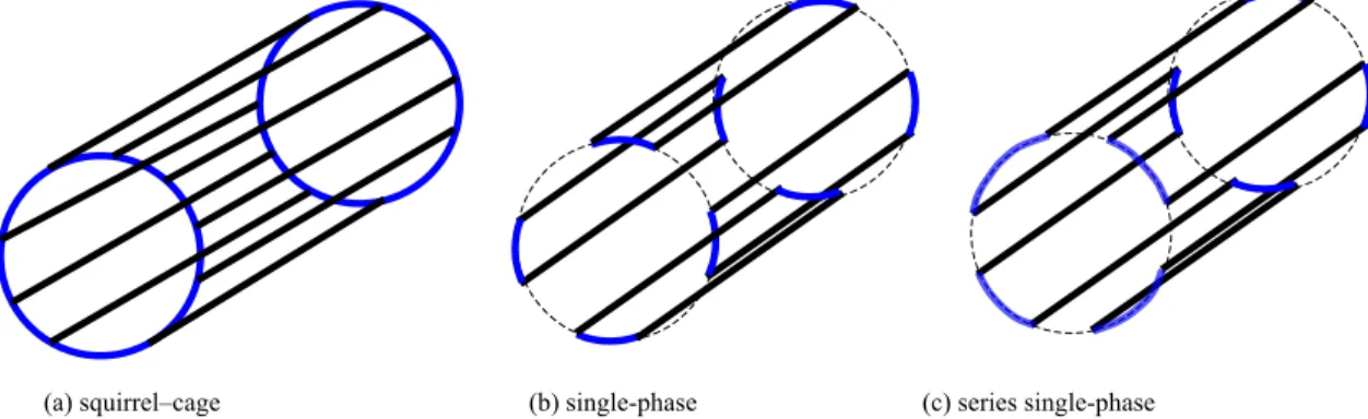
In this paper, a novel high frequency driven induction motor is proposed. Its stator poly-phase windings are the same as the low frequency induction motor. But its rotor conductor structure is different from the squirrel–cage rotor, as shown in Fig.1. In Fig. 1(a) is the squirrel–cage rotor conductor structure. In Fig. 1(b), only one phase of the rotor conductor is short-circuited. Or alternatively in Fig.
(a) squirrel–cage (b) single-phase (c) series single-phase Fig. 1. Different rotor conductor structure.
1(c), all the single-phase short-circuit rotor bars are series connected. These single-phase short-circuit rotor windings exhibit the different inductance spacing at different rotor position corresponding to the stator winding. This characteristic is similar with the reluctance machine [6,7], so it can be controlled alike that. To facilitate high frequency operation, the stator and rotor cores of the motor must be high frequency magnetic materials, such as ferrite or iron power. It further needs the following devices which are different from commonly used induction motor:
A. A high frequency capacitor is connected between stator winding and driver to form a resonant loop [8].
B. A phase-lock-loop circuit controls the output frequency of the high frequency driver so that the resonant current flows through stator winding maintains constant. C. Position sensors are attached at the rear of the motor to
help the driver commutate the stator windings so that it can start and reach its rated speed.
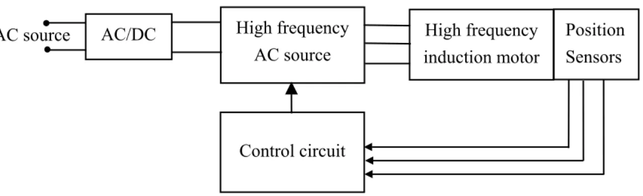
Fig. 2 shows the block diagram of the proposed induction motor. It accepts ac or dc source, in Fig. 2, a rectifier transfers ac to dc. A high frequency ac source transfers dc to 10-15kHz ac, because it must be operated at high frequency over 10kHz. The high frequency ac source contains a high frequency capacitor, power MOSFETs and driving circuit. It supplies high frequency current to the stator windings of the motor. But the same as the reluctance machines, stator winding commutated current flows only at correct rotor angles. Position sensors, which are mounted at the rear of motor, indicate these commutation angles and feedback to the control circuit. The control circuit contains phase-lock-loop and commutation control unit. The proposed motor can start and reach its rated speed by the help of phase-lock-loop and position sensors. In this paper, basic principle of the high frequency motor is introduced. Compared with the traditional induction motor, it can reduce acoustic mechanical vibration by driving at near ultrasonic frequency range [9-11]. A three-phase, 12-poles, 20W prototype was implemented. Experimental results show that the practical usage of the theory.
II. BASIC THEORY OF THE HIGH FREQUENCY INDUCTION MOTOR
One pair of the poles between rotor and stator of the presented induction motor is shown in Fig. 3. The motor has non-salient poles on its rotor and stator. On the rotor it has only single-phase single-turn conductor bar forming a short-circuit loop. This is the same as the traditional induction motor, its stator has poly-phase windings. A high-frequency ac source is applied to the stator windings to drive the motor. A resonant capacitor CS is connected in series with the stator winding to form a series-resonant loop. The switching frequency of ac source must be the same as the resonant frequency of the stator loop. The ac source produces square wave voltage and its output current is sinusoidal due to high quality resonance. Assume the magnitude of the high frequency resonant current of the stator winding is constant. As the above mentioned, it can be achieved by the phase-lock-loop control circuit.
The torque T produced in Fig. 3 can be expressed as: θ
d dW
T = (1)
where W is the energy stored at the gap between rotor and stator;
θ is the angle between rotor and stator poles. The single-phase rotor conductor winding has a different inductance spacing corresponding to the stator winding. The energy stored at the gap between rotor and stator can be expressed as: 2 1 ) ( 2 1 i i L W = θ (2)
where L is the inductance spacing corresponding to the stator winding per pole;
i1 is the to the instantaneous current of the stator
winding;
i2 is the to the instantaneous induced current of the
rotor winding. Fig. 2. Block diagram of the proposed motor.
AC/DC
AC source
High frequency
AC source
High frequency
induction motor
Position
Sensors
Control circuit
If the rotor and stator windings are coupled just like a transformer, the directions of two currents is opposite:
2
1 i
i =− (3)
The current can be expressed as: )
sin(
1 I t
i = m ω (4)
Substitute (3) and (4) into (2), the result is: ) ( ) ( sin 2 1 I2 2 ω Lt θ W =− m (5)
The instantaneous torque between rotor and stator for one pole is: θ θ ω d dL t I T msin ( ) ( ) 2 1 2 2 − = (6)
It can be separated into two terms:
θ θ ω θ θ d dL t I dL I T m mcos(2 ) ( ) 4 1 ) ( 4 1 2 + 2 − = (7)
The first term is a constant, so it can produce torque at extremely high frequency. The second term has a component of the twice of supplied frequency, it can be easily absorbed by the mechanical inertia of the motor. The switching frequency of driver can be selected at the half of the ultrasonic range that the human beings can’t hear. Its average torque is equal to the first term of (7). It can be expressed as the root mean square value of the stator current:
θ θ ) ( 2 1I2 dL Tav =− rms (8)
For a P-pole high frequency inductor, its output average torque is: θ θ ) ( 2 2 dL I P Tav =− rms (9)
Because the maximum flux density of the high frequency magnet is smaller than laminated steel, so the number of poles P must be larger than traditional induction motor. According to the above analysis, if the magnitude of stator current is constant and rotor position sensors guide the poly-phase stator windings to accept high frequency current at correct rotor angles, the motor can start and operate at high frequency. It is interesting that the new motor can be
controlled similar with the reluctance motor. The difference is that it produces repulsive force between rotor and stator poles but the reluctance motor is attractive. The commutation angles of the two machines are different.
III. EXPERIMENTAL RESULTS
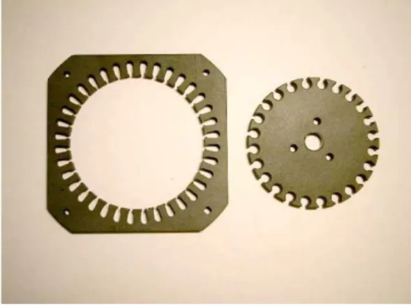
To demonstrate the theory, a 20W output three-phase 12-pole 110VAC 10~15kHz prototype of the presented high frequency induction motor was implemented. Its rotor and stator are all made of ferrite cores to reduce hysteresis and eddy-current losses, as shown in Fig. 4 and Table I.
Fig. 4. Ferrite cores for the high frequency induction motor. TABLE I
DIMENSIONS OF THE SELECTED FERRITE CORES (unit:mm).
material soft ferrite
initial permeability µr 2500
maximum frequency, fm 300kHz
stator rotor
outer 100x100(square) 69.0( diameter)
inner diameter 70.0 10.0
thickness 5.5 5.5
Fig. 3. One of the poles of the presented induction motor.
θ
i
i
resonant capacitor, Cs torque T
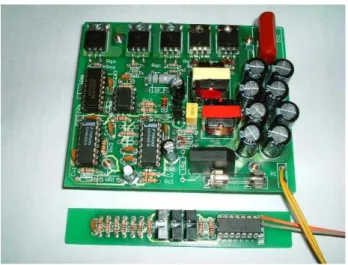
The rotor and stator with windings are shown in Fig. 5. The inductance distribution at different rotor position angle for one of the stator winding is shown in Fig. 6. A square-wave high frequency ac driver, as shown in Fig. 7, is connected to the stator windings. A module with three position sensors is also shown in Fig. 7. The photo of the motor and its driver as an ac fan is shown in Fig. 8.
Fig. 5. Rotor and stator with windings.
Fig. 6. Inductance distribution against rotor angle 0o-180o.
Fig. 7. High frequency ac driver and position sensor module.
Fig. 8. High frequency motor as an ac fan.
Fig. 9. Circuit diagram of the presented motor. 0 0.5 1 1.5 2 0 15 30 45 60 75 90 105 120 135 150 165 180 angle(degree) inductance(mH) +Vdc Cs motor Rotor position sensor Current sensor
AC/DC
AC 110V High frequencyPhase lock loop Commutation control Sc Sb Sa CH CL QH QL (bridge diodes)
The circuit diagram of the motor is shown in Fig. 9. It accepts ac 110V and a bridge-diode module rectifies ac to dc 150V. A half bridge high frequency inverter transfers dc to high frequency ac at 10~15KHz. A resonant capacitor CS connects high frequency source and stator windings. A phase-lock-loop circuit controls the output frequency of the high frequency in order to maintain constant resonant current. A current sensor is put on the stator loop to detect the magnitude of the resonant current and feedback to phase-lock-loop circuits such that the current is constant. Three low frequency switches Sa, Sb and Sc control the on/off of the stator windings. The position sensors guide these low frequency switches to perform commutation. The circuit parameters in Fig. 9 are listed in Table II:
TABLE II
CIRCUIT PARAMETER OF CONTROL BOARD.
Item Parameters
CH, CL 150µF/100VDC
QH, QL IRF640 200V/18A
CS 0.1µF/800V
Sa, Sb and Sc IRF840 500V/5A
Bridge diodes 2A/400V
Phase-lock-loop CD4046
Commutation control CD4042
Current sensor 0.5Ω/2W
The motor can maintain constant torque when the magnitude of stator current is constant and the low frequency switches turn on at the correct rotor angle when the inductance of winding is increasing. Its high frequency ac output voltage and current waveforms are shown in Fig. 10. It operates at 1200 rpm when the switching frequency is 10-15kHz.
Fig. 10. Output voltage and current waveforms of the high frequency driver. (50V/div, 5A/div, 25µs/div)
Fig. 11 shows three-phase stator current waveforms of the motor. Theoretically, the envelopes of these waveforms are square shapes when the switches turn on, but they are not. It is because that at the transient during turn-on, a spike of current occurs, and it must be a short time interval for the current to increase its rated value, as shown in Fig. 11.
Fig. 11.Three phase stator current waveforms. (2A/div)
IV. CONCLUSIONS
In this paper, a novel high frequency induction motor is introduced. It has only single-phase short-circuit rotor winding. So it exhibits different inductance spacing at different rotor position corresponding to stator winding. This characteristic is similar with the reluctance machine, and it can be controlled alike a reluctance motor. But its force is repulsive between rotor and stator poles. It must be driven at extremely high frequency to reduce acoustic noise by resonant method. Its rotor position sensors guide stator windings perform commutation to accept the resonant current at correct rotor angle. A phase-lock-loop helps the resonant current to maintain constant so that its output torque is also constant.
For a high-frequency based motor, the presented has the following improvements when compared with the previous motor [8]:
A. The resonant capacitor CS is on the driver module, not in the rotor, its rotor conductor short circuit bar is simple and easier to implement than wound rotor.
B. Rotor position sensors guide low frequency switches on/off according to correct angle that produces constant torque.
C. A phase-lock-loop controls the output frequency of driver so that the current flowing through stator is constant by current sensor feedback.
D. It uses five power MOSFET switches, the number is less than the six switches of three-phase bridge driver.
Our objective is to create a high-frequency driven induction motor. Frankly speaking, this motor has many defeats:
A. Rotor position sensor is inconvenient to be mounted in the motor. Sensorless techniques of rotor position are commonly used in motor control [12-14]. So the presented machine needs sensorless control to replace the position sensor.
B. It needs soft-switching techniques to turn on and off the low frequency switches to eliminate the spikes. Also, the time interval of increasing current when it turned on must be as short as possible.
C. Voltage stress of the three low frequency switches is much higher than the half-bridge switches. To reduce the cost of the driver, it needs to reduce the voltage stress of the switches.
In this paper, basic theory of the motor operation is introduced. Compared with the traditional induction motors, it can reduce acoustic noise of motor by driving near ultrasonic frequency range. In the future, advanced phase-lock-loop and position sensorless control will improve the performance of the motor.
REFERENCES
[1] B. K. Bose, Modern Power Electronics and AC Drives, Printice Hall, 2002.
[2] F. Blaschke, “The Principle of Field Orientation as Applied to the New Transvector Close-loop Control System for Rotating-field Machines,” Siemens Review, vol. 39, no. 5, pp. 217-220, May 1972. [3] R. Gabriel. W. Leohard and C. J. Nordby, “Field-oriented Control of a
Standard AC Motor Using Microprocessors,” IEEE Trans. Ind.
Applicat., vol. 16, no.2, pp. 186-192, 1980.
[4] T. G. Habetler, F. Profumo, M. Pastorelli and L. M. Tolbert, “Direct Torque Control of Induction Machines Using Space Vector Modulation,” IEEE Trans. Ind. Applicat., vol. 28, no.5, pp. 1045-1053, 1992.
[5] H. Kubota, K. Matsuse and T. Nakano, “DSP-based Speed Adaptive Flux Observer of Induction Motor,” IEEE Trans. Ind. Applicat., vol. 29, pp. 344-348, Mar./Apr. 1993.
[6] A. E. Fitzgerald Jr., C. Kingsley and S. D. Umans, Electric Machinery, McGraw-Hill, 1992.
[7] T. J. E. Miller, Brushless Permanent Magnet and Reluctance Motor
Drives, Clarendon Press, Oxford, 1989.
[8] C. Lin et. al, “Ultrasonic Driven Revolving Coil” in Proc. IEEE
International Electronic Machine and Drive Conference IEMDC,
pp.304-310, 2003.
[9] I. Takahashi and H. Mochikawa, “Optimum PWM waveforms of an Inverter for decreasing Acoustic Noise of an Induction Motor,” IEEE
Trans. Ind. Applicat., vol. 22, no.5, pp. 828-834, 1986.
[10] T. G. Habetler and D. M. Divan, “Acoustic Noise Reduction in Sinusoidal PWM Drives Using a Randomly Modulated Carrier,” in
Proc. IEEE Annual Power Electronics Specialist Conference, vol. 2,
pp.665-671, 1989.
[11] S. G. Otero and M. Devaney, “Minimization of Noise in Variable Speed Motors Using Modified Pulse Width Modulation (PWM) Drives,” in Proc. IEEE Annual Power Electronics Specialist
Conference, pp.126-131, 1992.
[12] J. Cilia, G. M. Asher, K. J. Bradley and M. Sumner, “Sensorless Position Detection for Vector-controlled Induction Motor Drives Using an Asymmetric Outer-section Cage,” IEEE Trans. Ind.
Applicat., vol. 33, pp. 1162-1169, 1997.
[13] H. Hofmann and S. R. Sanders, “Speed-sensorless Vector Torque Control of Induction Machines Using a Two-time-scale Approach,”
IEEE Trans. Ind. Applicat., vol. 34, pp. 169-177, 1998.
[14] V.-M. Leppanen and J Luomi, “Observer Using Low-frequency Injection for Sensorless Induction Motor Control – Parameter Sensitivity Analysis,” in Proc. IEEE International Electronic Machine