Ž .
Optics Communications 177 2000 363–368
www.elsevier.comrlocateroptcom
Colliding-pulse mode-locked semiconductor laser with a
multimode-interference waveguide amplifier
Chih-Chiarng Chen, Yean-Woei Kiang
), C.C. Yang
Department of Electrical Engineering, Graduate Institute of Communication Engineering, and Graduate Institute of Electro-Optical Engineering, National Taiwan UniÕersity, 1, RooseÕelt Road, Sec. 4, Taipei, Taiwan
Received 28 October 1999; received in revised form 4 February 2000; accepted 22 February 2000
Abstract
Ž .
We demonstrate numerically a novel colliding-pulse mode-locking CPM technique for semiconductor laser without
Ž . Ž .
using a saturable absorber. A multimode-interference MMI semiconductor optical amplifier SOA is used as the gain medium and the mode locker. Efficient pulse compression and stabilization of the two counter-propagating pulses are achieved based on the nonlinear-coupling effect, assisted with pulse collision, in the MMI SOA. Two initially different pulses tend to adjust each other, resulting in symmetric collision of two identical pulses. Such efficient pulse compression and stabilization mechanisms should lead to simple implementation of CPM semiconductor lasers. q 2000 Elsevier Science B.V. All rights reserved.
PACS: 42.55.Px; 42.79.Gn
Keywords: Semiconductor lasers; Colliding-pulse mode locking
Ž .
Colliding-pulse mode-locking CPM was the key technique for generating femtosecond pulses in dye lasers, which were the major tools for ultra-fast research in the 1980s. It was later applied to semi-conductor lasers, leading to femtosecond pulses after
w x
external-cavity dispersion compensation 1,2 . Basi-cally, a CPM laser includes a saturable absorber where the counter-propagating pulses collide. In col-lision, the two pulses enhance the pulse compression effect of each other through power dependent
ab-)
Corresponding author. Tel.: q886-2-2363-5251 ext. 438; fax:
q886-2-2365-2637; e-mail: [email protected]
w x
sorption 3,4 . Such a process includes an implication that the two colliding pulses tend to adjust them-selves such that they enter the saturable absorber from the two ends at the same time and hence collide at the center of the saturable absorber. This adjust-ment is attributed to the fact that the earlier-arriving pulse saturates the absorption for effectively enhanc-ing the strength of the leadenhanc-ing edge of the later-arriv-ing pulse. This equivalently results in the advance of the later-arriving pulse and the delay of the earlier-arriving pulse. Such an adjustment is important for stabilizing the mode-locked pulses.
Such a stabilization mechanism does not exist if the saturable absorber is replaced by a saturable gain 0030-4018r00r$ - see front matter q 2000 Elsevier Science B.V. All rights reserved.
Ž .
medium. Therefore, a saturable absorber is required in a conventional CPM laser for generating stable pulses. However, this requirement represents more loss and complexity for the laser. If a gain medium of a properly designed configuration can be used to replace the saturable absorber with the same function kept, CPM lasers can be simplified. In this letter, we propose a novel configuration for CPM semiconduc-tor laser without the need of a saturable absorber. It is based on the nonlinear coupling effect in a
multi-Ž .
mode-interference MMI semiconductor optical
am-Ž .
plifier SOA or a directional-coupler amplifier. We will use an MMI SOA structure to numerically demonstrate the feasibility of CPM.
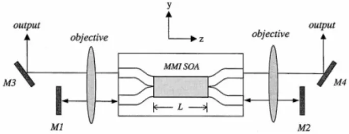
The layout of such a laser system is shown in Fig. 1, in which the MMI SOA with four inputroutput ports is placed at the center of the resonance cavity. Assume that there exist two waveguide modes in the MMI SOA, which is a ridge-loading waveguide. The
Ž
inputroutput ports are assumed to be passive can be implemented through quantum well intermixing
.
techniques . Laser signal oscillates between mirrors M1 and M2 and outputs are obtained from the reflection of mirrors M3 and M4. For convenience, the two ports corresponding to mirrors M1 and M2 will be called the bar-ports and those corresponding to M3 and M4 are called the cross-ports. For numeri-cal simplicity, we neglect all the reflections from the connections between the MMI SOA and the four passive waveguide ports and from the interfaces between the passive waveguide ports and the air. The reflectivities of the four mirrors are assumed to be 100%. Therefore, we need not consider the boundary conditions in the z-direction. It is also assumed that the two external-cavities are quite long so that gain can essentially recover from saturation when the
Fig. 1. Layout of the CPM semiconductor laser. The MMI SOA is placed at the center of the cavity, which is formed with mirrors M1 and M2. Counter-propagating pulses oscillate through the two bar-ports.
oscillating pulses return to the MMI SOA. Typically, a 15-cm long external-cavity length is sufficient. In addition, the length of the MMI SOA is assumed to be one-half beat length such that a weak signal incident from one side of the lateral dimension
Ž .
emerges from the other side cross-port . As shown in Fig. 1, the pulses enter from the two ends of the MMI SOA on the same side of the lateral dimension, i.e., bar-ports.
To simulate the collision of pulses in the MMI SOA, we expanded the TE polarized electric field
Ž .
into two waveguide modes modes 1 and 2 , each of which propagates in both qz and yz directions. The corresponding four slowly-varying wave
ampli-q
Ž . qŽ . yŽ . yŽ .
tudes, A1 z,t , A2 z,t , A1 z,t and A2 z,t ,
satisfy the following equations:
1 E E q q A1Ž2 .
Ž
z ,t.
ž
n E tg E z/
1 q sŽ
1 q ja g.
Ž
z ,t A.
Ž
z ,t.
1Ž2 . 1Ž2. 2 1 q " jD b z qŽ
1 q ja g.
Ž
z ,t A.
Ž
z ,t e.
x 2Ž1. 2 1 q y r A1Ž2 .Ž
z ,t.
Ž .
1 2 1 E E y y AŽ
z ,t.
1Ž2 .ž
n E tg E z/
1 y sŽ
1 q ja g.
1Ž2 .Ž
z ,t A.
1Ž2.Ž
z ,t.
2 1 y . jD b Ž zyL. qŽ
1 q ja g.
xŽ
z ,t A.
2Ž1.Ž
z ,t e.
2 1 y y r A1Ž2 .Ž
z ,t.
Ž .
2 2 ` 2 Ž . Ž . Ž . with g1Ž2. z, t ' Hy`g y, z, t F1Ž2. y d y and ` Ž . Ž . Ž . Ž . gx z,t ' Hy`g y, z,t F y F1 2 y d y. Ž .Here, g y, z,t is the gain constant distribution
Ž .
and F1Ž2 . y is the normalized lateral pattern of
Ž .
mode 1 2 with a sinusoidal pattern inside the ridge region and exponential decay outside. Parameter D b
sb y b1 2 is the difference between the propagation
constants of the two modes, n is the group velocity,g
Ž .
r is the loss constant, a s6 is the linewidth
Ž .
of the MMI SOA. Note that the variation along the
Ž .
epitaxial growth direction x has been averaged out.
Ž .
Also, the gain constant g y, z,t is related to the
< Ž .<2
optical intensity E y, z,t through the equation
E g y, z ,t
Ž
.
E t < <2 g y g y, z ,t0Ž
.
E y, z ,tŽ
.
s y g y, z ,tŽ
.
Ž .
3 tc E rssat Žwhere g0 is the small-signal gain constant, tc s1
. Ž .
ns is the carrier lifetime, s s 8 = 0.43 mm is the effective cross-sectional area of the waveguide, and
Ž .
Esat s5 pJ is the saturation energy. Note that we
are concerned with the effects of carrier dynamics on
pulse evolution in the time range from hundreds to a few ps over a lateral dimension of around 8 mm. Within such a short time range, the effects of carrier
w x
diffusion can be neglected 5 . For instance, a lateral diffusion time constant at 1.4 ns was estimated for a scale size of 1.5 mm in a GaAsrAlGaAs structure
w x6 . In our case, with the 8-mm concerned lateral
dimension, the diffusion time constant would exceed 10 ns, which is much larger than the pulse width and carrier lifetime. Therefore, the diffusion factor is
Ž .
neglected in Eq. 3 . However, under other condi-tions the diffusion effect may deserve further investi-gation.
For numerical simulation, the time-domain
travel-w x
ing-wave model 7 was adopted. However, instead
Ž . Ž .
of applying the first-order finite-difference
approxi-w x
mation to the partial derivatives 7 , we analytically solved the differential equations in each small seg-ment D z along the axis of the MMI SOA.
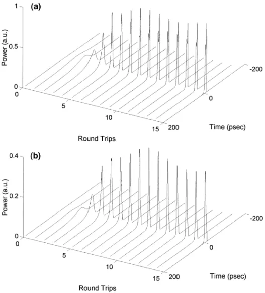
Ž . Ž .
Fig. 2 a and Fig. 2 b show the pulse evolution emerging from the cross- and bar-port, respectively. It was assumed that two initially identical long pulse of width 100 ps and energy 0.04 Esat entered the MMI SOA simultaneously. Therefore, the evolutions of the two counter-propagating pulses are symmetric. The small-signal gain factor and internal loss coeffi-cient in the MMI SOA were set at 20 dB and 19 cmy1
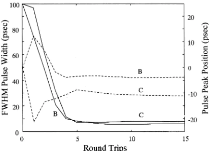
, respectively. One can see that pulses from both cross- and bar-port are compressed along oscil-lation. After several round-trips, the pulses approach their asymptotic shapes. Fig. 3 shows the evolutions of the FWHM pulse width and the pulse peak
posi-Ž . Ž .
tion in the cross- C and bar-port B . One can see that after several round-trips, the pulse width and temporal position reach almost steady-state values. This is an indication that mode locking is feasible in such a laser system.
It is recalled that like a directional-coupler SOA, an MMI SOA with one-half beat length can result in
w x
the nonlinear coupling and pulse breakup effects 8 . In other words, because of gain saturation, different temporal portions of a pulse will emerge from either the bar- or cross-port. In our simulation, we find that
Ž .
a fraction of the central portion near the peak of the pulse emerges from the bar-port after a single pulse
Ž .
Fig. 3. Evolutions of the FWHM pulse widths solid curves and
Ž . Ž .
pulse peak positions dashed curves of the bar-port labeled B
Ž .
and cross-port labeled C pulses.
propagating through the MMI SOA. This bar-port pulse has a width shorter than the input pulse. Such a pulse compression mechanism in a
directional-cou-w x w x
pler SOA 9 or an MMI SOA 10 has been pro-posed for passive mode locking of a semiconduc-tor laser with a ring-cavity configuration. Here, it is discovered that with collision of two counter-propagating pulses, as shown in Fig. 1, the pulse compression is more efficient. Therefore, with pulse oscillating between mirrors M1 and M2, pulses are continuously narrowed. Such a mechanism is ex-pected to result in effective CPM. Although group-velocity dispersion was not considered in our simula-tion, the pulse width can reach a steady state. This is attributed to the fact that both the clipping effect
Ždue to linear coupling on the pulse leading side and. Ž
the effective intensity depression due to gain
satura-.
tion on the trailing side diminish gradually as pulse width becomes narrower. The pulse position reaches its steady state value because the aforementioned clipping effect on the leading side stops the pulse advance, which is due to gain saturation. The mutual enhancement of pulse compression is attributed to the fact that the coexistence of the counter-propagat-ing pulses can enhance nonlinear couplcounter-propagat-ing in the MMI SOA. We also tried the case that two counter-propagating pulses entered the MMI SOA on differ-ent sides of the lateral dimension and found that the mutual enhancement of pulse compression did not exist.
As mentioned before, a pulse position stabiliza-tion mechanism exists in the saturable absorber of a conventional CPM laser. Such a mechanism may not exist in a single-waveguide-mode SOA. However, it exists in the MMI SOA, used for our CPM laser. The four curves in Fig. 4 show the bar-port output evolu-tions of the FWHM pulse widths and pulse peak positions of the two counter-propagating pulses, which enter the MMI SOA at different times by 165 ps. One can see that after several round-trips, the pulse widths and peak positions approach their asymptotic values. Of particular interest is that the earlier-arriving pulse has been delayed by 129 ps and the later-arriving pulse has been advanced by 36 ps, leading to the result that two pulses collide at the center of the MMI SOA. This is the mechanism for pulse position stabilization, similar to a conventional CPM laser.
Ž .
Fig. 4. Evolutions of the FWHM pulse widths solid curves and
Ž .
pulse peak positions dashed curves of the bar-port outputs for
Ž .
the earlier-arriving pulse labeled E and later-arriving pulse
Žlabeled L ..
Shown in Fig. 5 are the bar-port output evolutions of the pulse energies and the FWHM pulse widths of two counter-propagating pulses, which enter the MMI SOA simultaneously. Here, the two initial pulses
Ž .
have the same width 100 ps , but different pulse
Ž .
energies one at 0.04 Esat and the other at 0.01 Esat . It can be seen that after several round-trips, the pulse widths and energies approach their asymptotic val-ues. Note that the energies of the two pulses become equal after one round-trip. This again leads to sym-metric collision. In other simulations, we also find that the collision between two pulses of different widths tends to equalize their widths along
oscilla-Ž .
Fig. 5. Evolutions of the FWHM pulse widths solid curves and
Ž .
pulse energies dashed curves of the bar-port outputs for the
Ž . Ž .
low-energy pulse labeled L and high-energy pulse labeled H .
tion. The adjustments of pulse position and width are attributed to the fact that both pulses in the bar-port would receive the most gain when the system be-comes symmetric. The detailed explanations will be presented in another publication.
Note that our theoretical model does not include the effects of gain dispersion, which are important for subpicosecond signals. The effective
group-Ž .
velocity dispersion GVD due to gain dispersion may cause pulse broadening. To evaluate this effect,
w x
one can define a dispersion length LD 11 as 0.36tp2 0.36tp2
L sD s
2 eff
a g T0 2 b2
where T2 is the gain relaxation time, a is the linewidth enhancement factor, g0 is the unsaturated gain constant, tp is the FWHM pulsewidth, and
beffsa g T2
is the effective GVD parameter
intro-2 0 2
duced in a manner similar to that of optical fiber. For
a s 6, T s 0.1 ps, and g s 10 000 my1
, beff is
2 0 2
600 ps2rm. The effect of GVD due to gain
disper-sion becomes important for an amplifier of length
L G L . In our simulations, the smallest FWHMD
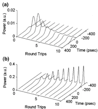
Fig. 6. Evolutions of the counter-propagating pulses when the MMI SOA is replaced by a single-waveguide-mode SOA for
Ž . Ž .
pulsewidth is about 5 ps. Hence, the corresponding dispersion length is L ( 1.5 cm, which is muchD
Ž .
larger than the length 665 mm of our MMI SOA. Therefore, this dispersion effect is negligible. Never-theless, the gain-induced GVD would be important for the subpicosecond case and its effects deserve further study.
To assure that the MMI configuration is required
Ž .
for the pulse stabilization mechanism, Fig. 6 a and
Ž .
Fig. 6 b demonstrate pulse evolution when the MMI SOA is replaced by a single-waveguide-mode SOA and the two counter-propagating pulses enter the SOA with one delayed by 75 ps from the other. One
Ž .
can see that the delayed one diminishes a and the
Ž .
other grows and becomes narrower b . The growing one advances during oscillation. However, it does not seem to reach a steady state.
In summary, we have numerically demonstrated the feasibility of a novel CPM semiconductor laser without using a saturable absorber. The nonlinear coupling effect, assisted with pulse collision, in an MMI SOA led to efficient pulse compression and stabilization. Two initially different pulses, which might come from noise bursts in a real laser system, would evolve into symmetric collision of two identi-cal pulses. These results guarantee the feasibility of a CPM laser.
Acknowledgements
This research was supported by the grants NSC 88-2215-E-002-016, NSC 88-2112-M-002-004, NSC 88-2215-E-002-012, and NSC 88-2215-E-002-040 from National Science Council, the Republic of China.
References
w x1 Y.K. Chen, M.C. Wu, T. Tanbun-Ek, R.A. Logan, M.A.
Ž .
Chin, Appl. Phys. Lett. 58 1991 1253.
w x2 C.F. Lin, C.L. Tang, Appl. Phys. Lett. 62 1993 1053.Ž . w x3 D.J. Jones, L.M. Zhang, J.E. Carroll, D.D. Marcenac, IEEE
Ž .
J. Quantum Electron. 31 1995 1051.
w x4 W. Chen, J. Zhu, S. Liu, IEEE J. Quantum Electron. 31 Ž1995 1663..
w x5 G.P. Agrawal, A. Olsson, IEEE J. Quantum Electron. 25 Ž1989 2297..
w x6 P. LiKamWa, A. Miller, C.B. Park, J.S. Roberts, P.N.
Rob-Ž .
son, Appl. Phys. Lett. 57 1990 1846.
w x7 L.M. Zhang, S.F. Yu, M.C. Nowel, D.D. Marcenac, J.E.
Ž .
Carroll, R.G.S. Plumb, IEEE J. Quantum Electron. 30 1994 1389.
w x8 S. Trillo, S. Wabnitz, J.M. Soto-Crespo, E.M. Wright, IEEE
Ž .
J. Quantum Electron. 27 1991 410.
w x9 C.W. Hsu, C.C. Yang, Opt. Lett. 21 1996 878.Ž .
w10 J.C. Lai, Y.W. Kiang, C.C. Yang, IEEE J. Quantum Elec-x
Ž .
tron. 35 1999 1630.