Design of Visible Light Communication System for Maintaining
Uniform Data Rate
Jiun-Yu Sung,
1Wan-Feng Lin,
1Yu-Fu Wu,
1Chi-Wai Chow,
1and Chien-Hung Yeh*
2,31
Department of Photonics and Institute of Electro-Optical Engineering, National Chiao Tung
University, Hsinchu 30010, Taiwan
2
Information and Communications Research Laboratories, Industrial Technology Research Institute,
Hsinchu 31040, Taiwan
[email protected]
3
Graduate Institute of Applied Science and Engineering, Fu Jen Catholic University, New Taipei
24205, Taiwan
ABSTRACT
Light-emitting diode (LED) is gradually replacing the fluorescent lamp for lighting. Higher modulation bandwidth of LEDs makes the additional application of visible light communication (VLC) possible. Every location of a VLC system should be provided by equal data rate for smooth communication. However, locations away from the LED lamp have less power. These low-power locations have lower signal-to-noise ratio (SNR); and hence lower data rate can be achieved. For achieving high capacity VLC, strategies should be adequately provided to mitigate this problem. Moreover, for some real-time continuous applications, such as video and voice, latency reduction plan should also be considered.
In this paper, an orthogonal frequency-division multiplexing access (OFDMA) based system was proposed to solve the above problem. Because we do not use time-division multiplexing access (TDMA) based system, the latency issue can be reduced. The OFDMA based system is also beneficial for large scale operation because the user bandwidth is not reduced by TDM mechanism. Signal-to-noise-plus-interference ratio (SNIR) distribution of the VLC system is designed to ensure uniform and optimal system capacity. Discrete multi-tone (DMT) is used for this VLC system. The DMT subcarriers are bit-loaded depending on the LED frequency response. More subcarriers are allocated for communication at low SNIR locations. Hence, nearly equal data rate can be provided everywhere. Demonstration of 17 Mb/s/LED data rate was provided.
Keywords: Visible light communication (VLC), indoor communication, access, orthogonal frequency-division
multiplexing (OFDM), light-emitting diode (LED).
1. INTRODUCTION
Light-emitting diode (LED) technology has been developed prosperously. With its characteristics of being high-illuminant and longer life time, LED is seen to be a promising candidate for future high-illuminant source. Additionally, compared to traditional fluorescent lamp, LED has higher modulation bandwidth. It is thus desirable to use the lighting LED to realize visible light communication (VLC) 1.
To achieve smooth indoor communication, requirement of uniform signal-to-noise-plus-interference ratio (SNIR) distribution among different locations in the system should be satisfied. This high SNIR requirement may be realized by having all the indoor LEDs synchronously transmitting identical signals to reduce the signal interference at the receivers. Because the interference among signals from different LEDs is minimized, SNIR will be highly related to only the receiving power. Hence, adequate allocation of LEDs positions to achieve uniform power field within the VLC system is important to obtain uniform SNIR distribution 2, 3. For real VLC system, different users may share the whole system
capacity by time-division multiplexing access (TDMA) mechanism; and, despite of their locations, identical signal quality may be achieved resulted from the uniform SNIR distribution. Though this kind of TDMA system can be easily deployed, it is not applicable to large-scale VLC system with tremendous amount of users. While the amount of the system users becomes large, the capacity sharing characteristic of TDMA may seriously decrease the capacity available for individual user. Additionally, while the space dimension of the system is large, the LEDs will not be used efficiently because LEDs far away from a specific location can contribute only slight power for communication. The total capacity
of the whole system will hence be limited. Even though the whole indoor space may be divided into several group areas (GAs) communicating independently (signals from different GAs are not synchronous), high interference may occur at the boundaries of each GA. Complicated allocation strategies may be involved for reducing the interference at the GA boundaries.
In this paper, to solve the abovementioned problems, an orthogonal frequency-division multiplexing access (OFDMA) based VLC system is proposed. Discrete multi-tone (DMT) is used; and the subcarriers of each DMT signal are specifically allocated for communication according to where the users are located at. By adequate design of the nearby LEDs’ transmission signal, interference among signals from different LEDs is reduced. Approximate capacity can be achieved at all locations within the system by flexible bandwidth allocation and bit-loading technique. Moreover, the whole system is discretized into several independent sub-units; hence, the system can be easily upgrade by installing or removing individual sub-unit.
2. PRINCIPLES
There are three points in this section. First, the configuration of the proposed OFDMA based VLC system is described. Second, the working principles of the proposed system are illustrated. Finally, the power and SNIR distribution and behavior of the proposed system are analyzed.
2.1 System configuration
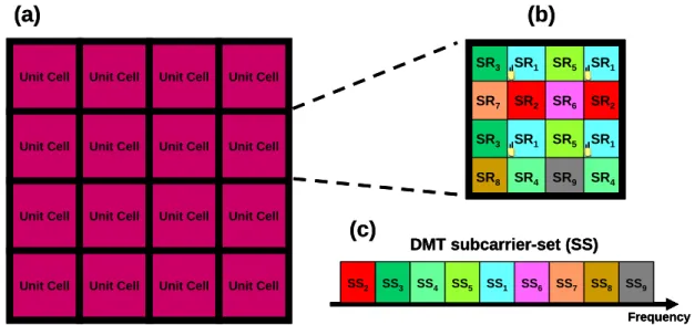
The configuration of the proposed system is shown in Fig. 1(a).The whole VLC system is divided into several rectangular areas, each named a unit cell; a unit cell is composed of even smaller 4x4 rectangular pieces, each named a sub-region (SR) as shown in Fig. 1(b). As shown in Fig. 1(c), different SRs receive different data from the whole VLC system using different DMT subcarriers (will be further illustrated in the “Working principle” section); each SR is indexed by “1”-“9” (SR1-SR9) for distinguishing purpose. Every SR1 is installed with a LED (or a LED array). Any VLC
system is constructed by repeatedly setup joint unit cells. Each shape of system layout can be realized by specifically place the unit cells. System reconfiguration involves to plug in/out only unit cells; hence it is highly scalable.
SS2 SS3 SS4 SS5 SS1 SS6 SS7 SS8 SS9 DMT subcarrier-set (SS) Frequency SR3 SR3 SR8 SR1 SR2 SR1 SR4 SR5 SR6 SR5 SR9 SR2 SR1 SR4 SR1 SR7 Unit Cell Unit Cell Unit Cell Unit Cell
Unit Cell Unit Cell
Unit Cell Unit Cell Unit Cell Unit Cell Unit Cell Unit Cell Unit Cell Unit Cell Unit Cell Unit Cell
(a)
(b)
(c)
SS2 SS3 SS4 SS5 SS1 SS6 SS7 SS8 SS9 DMT subcarrier-set (SS) Frequency SS2 SS3 SS4 SS5 SS1 SS6 SS7 SS8 SS9 SS2 SS3 SS4 SS5 SS1 SS6 SS7 SS8 SS9 SS2 SS3 SS4 SS5 SS1 SS6 SS7 SS8 SS9 DMT subcarrier-set (SS) Frequency SR3 SR3 SR8 SR1 SR2 SR1 SR4 SR5 SR6 SR5 SR9 SR2 SR1 SR4 SR1 SR7 SR3 SR3 SR8 SR1 SR2 SR1 SR4 SR5 SR6 SR5 SR9 SR2 SR1 SR4 SR1 SR7 SR3 SR3 SR8 SR1 SR2 SR1 SR4 SR5 SR6 SR5 SR9 SR2 SR1 SR4 SR1 SR7 Unit Cell Unit Cell Unit Cell Unit CellUnit Cell Unit Cell
Unit Cell Unit Cell Unit Cell Unit Cell Unit Cell Unit Cell Unit Cell Unit Cell Unit Cell Unit Cell Unit Cell Unit Cell Unit Cell Unit Cell
Unit Cell Unit Cell
Unit Cell Unit Cell Unit Cell Unit Cell Unit Cell Unit Cell Unit Cell Unit Cell Unit Cell Unit Cell Unit Cell Unit Cell Unit Cell Unit Cell Unit Cell Unit Cell
(a)
(b)
(c)
Fig. 1. The configuration of the proposed system. (a) the system structure. (b) Perspective of a unit cell. (c) Subcarrier-set division of the DMT signal.
2.2 Working principle
DMT is used in the proposed system for efficiently and flexibly using the LED bandwidth. Subcarriers of the DMT signal are adequately allocated for different SRs. Every LED located at SR1 transmits different DMT signals at the same
time. A DMT signal transmitted from the LED at each SR1 is shared by the surrounding eight SRs (SR2-SR9).
Subcarriers of each DMT signal is divided into 9 subcarrier-sets (SSs) (as shown in Fig. 1(c)), each indexed from “1”-“9” (SS1-SS9). Each SS with a specific index number is used in a particular SR which has the same index number. For
surrounded by two distinguished nearest LEDs (SR1). For avoiding interference aroused by the two distinguished DMT
signals transmitted from two different SR1, it is required that the data loaded by each SS, which is specifically allocated
to the corresponding SR, of the two neatest LEDs should be identical. For example, a specific SRm surrounding by two
nearest LEDs at the SR1 communicates using SSm of the two LEDs, where m is an arbitrary number of “2”-“5.” The SS
allocation mechanism for SR6-SR9, which have four distinguished surrounding LEDs (SR1), follows the same principle;
which means the surrounding four LEDs transmit the same data at SSq for communication at the surrounded SRq, where
q is an arbitrary number of “6”-“9.”
While the above principles are used for communication, there remains negligible interference between boundaries of different nearby LEDs (SR1) because they transmit the same data using specific SS at the same time. Moreover, the
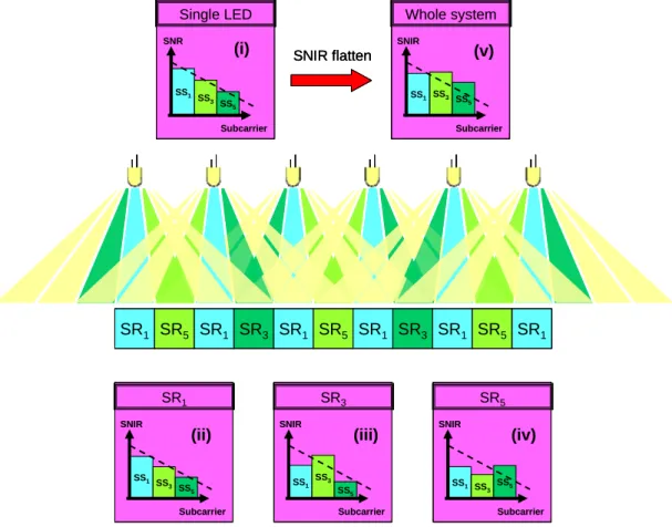
bandwidth of single LED is maximally used by using DMT modulation format; and the power of the nearby LEDs can also be efficiently used by an arbitrary surrounded SR by superposition mechanism. Under fixed environmental noise level, the superposition induced power enhancement may contribute to higher signal-to-noise ratio (SNR), and thus higher modulation format may be used for the SSs to increase the total system capacity. Schematic illustration of a one dimensional system is shown in Fig. 2. The frequency response of each LED is shown in inset (i) of Fig. 2. The SNR of each LED degrades at high frequency, which is limited by the available bandwidth of the LED. Each SR1 is installed
with a LED, and communicates using SS1 at the low frequency band. As shown in inset (ii) of Fig, 2, the SNIR of SS1 is
slightly degraded resulted from signal interference among LEDs at nearby SR1. The SNIR degradation at SR1 may be
mitigated by moderately choosing the distance of the LED separation distance. SS3 and SS5 of one LED are respectively
used for communication at SR3 and SR5 beside the LED. As shown in inset (iii) and (iv) of Fig. 2, the SNIR is enhanced
at SR3 and SR5 by power superposition of the nearby LEDs which transmit identical data at the same SSs. Because only
SSs with negligible interference are used for communication at the specific SRs, the final system SNIR will become flatten as shown in inset (v) of Fig. 2. It should be noticed that the allocation of SS1-SS9 may not be arranged in
frequency according to the index order. The arrangement of SS1-SS9 in frequency is determined by having the maximal
total system capacity.
SR1 SR5 SR1 SR3 SR1 SR5 SR1 SR3 SR1 SR5 SR1 SR1 SS1 SS 3 SS 5 Subcarrier SNIR SR3 SS1 SS3 SS5 Subcarrier SNIR SR5 SS1 SS3 SS5 Subcarrier SNIR Single LED SS1 SS 3 SS 5 Subcarrier SNR Whole system SS1 Subcarrier SNIR SS3 SS 5 SNIR flatten (i)
(ii) (iii) (iv)
(v) SR1 SR5 SR1 SR3 SR1 SR5 SR1 SR3 SR1 SR5 SR1 SR1 SS1 SS 3 SS 5 Subcarrier SNIR SR3 SS1 SS3 SS5 Subcarrier SNIR SR5 SS1 SS3 SS5 Subcarrier SNIR Single LED SS1 SS 3 SS 5 Subcarrier SNR Whole system SS1 Subcarrier SNIR SS3 SS 5 SNIR flatten SR1 SR5 SR1 SR3 SR1 SR5 SR1 SR3 SR1 SR5 SR1 SR1 SR5 SR1 SR3 SR1 SR5 SR1 SR3 SR1 SR5 SR1 SR1 SS1 SS 3 SS 5 Subcarrier SNIR SR1 SS1 SS 3 SS 5 Subcarrier SNIR SR3 SS1 SS3 SS5 Subcarrier SNIR SR3 SS1 SS3 SS5 Subcarrier SNIR SR5 SS1 SS3 SS5 Subcarrier SNIR SR5 SS1 SS3 SS5 Subcarrier SNIR Single LED SS1 SS 3 SS 5 Subcarrier SNR Single LED SS1 SS 3 SS 5 SS1 SS 3 SS 5 Subcarrier SNR Whole system SS1 Subcarrier SNIR SS3 SS 5 Whole system SS1 Subcarrier SNIR SS3 SS 5 SNIR flatten (i)
(ii) (iii) (iv)
(v)
2.3 Power and SNIR analyses
For practically analyzing the power and SNIR distribution within the VLC system, we first measured the power field of a commercially available while light LED from Cree (XLampXR-ELED); the power and SNIR distribution is calculated by superposition and interference of identical Cree LEDs allocated within an infinitely large VLC system, where LED separation is 5 cm. Fig. 3 shows the power and SNIR distribution of the VLC system. In Fig. 3(a), the 4x4 SRs circled by the dash line is a unit cell as shown in Fig. 1. It is seen that there are only three types of power distribution, named “P1,” “P2,” and “P3” in a unit cell. Each P1 region corresponds to SR1, where a LED is installed; the DMT signal transmitted
from the LED is divided into nine SSs, each is allocated for communication at the corresponding SRs. The 3x3 SRs which share the same DMT signal from the center LED is circled by solid line in Fig. 3(a). Because the proposed VLC system is symmetrical in power distribution, these 3x3 SRs theoretically include all the combination of cases of the VLC system; hence only the 3x3 SRs is considered in our analysis. The SNIR distribution within the 3x3 SRs is shown in Fig. 3(b). It is seen that the lowest SNIR is around 6.9 dB at the boundary of “P1” region. Nearly all places within the VLC system have SNIR larger than 10 dB. The SNIR is rather smooth within each SR space; hence the capacity and bit error rate (BER) should be similar at any location within each SR. There are two distinguished differences between the power distribution and the SNIR distribution in the VLC system. First, it can be seen that the SNIR distribution has discrete behavior at the boundaries of each SRs, which means the SNIR change is sharp at the boundaries of neighbor SRs. This phenomenon comes from the fact that signals from different LEDs may either be an interference source or a power enhancement source depending on the place of the SRs and their allocated SSs. Second, though “P2” regions have the highest total field power, the highest SNIR do not appear at “P2” regions. Despite having lower total receiving power, “P3” regions have the highest SNIR. This comes from the fact that all the four LEDs surrounding “P3” provide the same data to “P3” regions. Though “P3” regions still suffers from interference from farther LEDs, the power of the interference is weak and cause negligible influence on “P3” regions. This result shows that high total power does not always guarantee high SNIR, which contradicts the behavior of typical TDMA based VLC systems.
Fig, 3. Power and SNIR distribution among the system. (a) Power distribution [color bar unit: linear]; (b) SNIR distribution [color bar unit :dB].
3. SIMULATION
In this section, we will further analyze our proposed system through simulation using MATLAB. As discussed in section 2, because our proposed system is highly symmetrical in structure and power distribution, only one 3x3 SRs which includes all the nine SSs of a DMT signal is analyzed. To completely analyze all the signal performance within the proposed system, the 3x3 SRs are divided into 41x41 points, which signifies the receiver location resolution is 0.1875 cm in our simulation. The sum of background noise and all the electrical induced statistical noise is assumed to be -20 dB of the peak power of a single LED. DMT occupying 8 MHz bandwidth with 128 FFT size is used for the transmission.
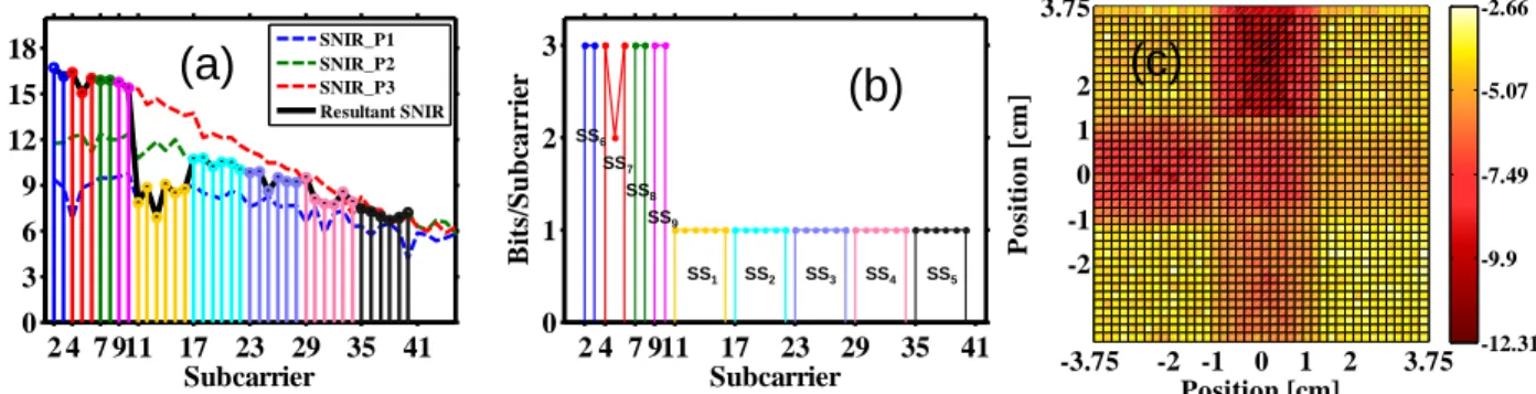
Fig, 4 is the simulation results. Fig. 4(a) is the average SNIR performance of different DMT subcarriers respectively at “P1”-“P3” regions while signals from center and its neighbor LEDs carry the same data. As shown in Fig. 3, P3 has the highest SNIR because of less interference from other LEDs. P1 has worse SNIR caused by serious interference from
nearby LEDs. However, different SSs are used at different SRs, and the resultant SNIR performance will behave as the black curve. Fig. 4(b) is the bit-loading strategy for different DMT subcarriers. The loaded bits for each subcarrier is determined by its SNIR. Higher SNIR may allow higher modulation format; the resultant SSs allocation is determined by having the total capacity maximal. Fig. 4(c) is the simulated BER at different points. It is seen that forward error correction (FEC) threshold of 3.8x10⁻³ can be achieved at every point of the system. One SR has significant lower BER
(~ 10-12) because its SNIR is far higher to the SNIR required to achieve the FEC threshold but less for the threshold of
higher modulation format.
2 4 7 911 17 23 29 35 41 0 3 6 9 12 15 18 Subcarrier SNIR [ d B ] SNIR_P1 SNIR_P2 SNIR_P3 Resultant SNIR
(a)
2 4 7 911 17 23 29 35 41 0 1 2 3 Subcarrier B it s/ Subc a rr ie r SS1 SS6 SS7 SS8 SS9 SS2 SS3 SS4 SS5(b)
-3.75 -2 -1 0 1 2 3.75 -2 -1 0 1 2 3.75 Position [cm] Posit ion [ cm] -12.31 -9.9 -7.49 -5.07 -2.66(c)
Fig. 4. Simulation results. (a) The SNIR performance for 5 cm LED separation. (b) The bit-loading strategy. (c) BER performance within the VLC system. [Color bar unit: [loag10(BER)]]
4. EXPERIMENT
To verify the feasibility of the system, a one-dimensional layout using two LEDs was demonstrated. Fig. 5 is the experimental setup. Only two SSs were divided for the DMT signal because SR1 and SR1’ are symmetrical. The DMT
signal was generated off line using MATLAB and fed into the arbitrary waveform generator (AWG). The DMT signal has 128 FFT size occupying around 7 MHz bandwidth. Two Cree LEDs were respectively modulated by two distinguished DMT signal. Light emitting from the LED was received by a photo-diode (PD) cascaded by a scope after 50 cm free space transmission. Resulted from the insufficiency of equipment in our lab, the two DMT signals were numerically added to emulate the interference and power enhancement process of the two lights.
Scope
ScopeAWG
AWG SR1’ (Sub. 2-25) (8PSK) SR2 (Sub. 26-57) (QPSK) SR1 (Sub. 2-25) (8PSK) PD LEDsScope
Scope
Scope ScopeAWG
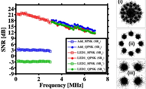
AWG AWG SR1’ (Sub. 2-25) (8PSK) SR2 (Sub. 26-57) (QPSK) SR1 (Sub. 2-25) (8PSK) SR1’ (Sub. 2-25) (8PSK) SR2 (Sub. 26-57) (QPSK) SR1 (Sub. 2-25) (8PSK) PD PD LEDs LEDsResults are shown In Fig. 6. It can be seen that at SR1, the 8-phase shift keying (PSK) loaded at SS1 transmitted from
LED at SR1 can be decoded and clear constellation separation can be observed. At SR2, the 8-PSK SS1 can not be
successfully decoded because of serious interference between the SS1 and SS1’. Numerical addition can provide about
1.5 dB SNIR gain for SS2 at SR2. This is a result of superposition induced power enhancement as discussed in section 2.
At SR1, SS1 with 8-PSK bit-loaded subcarriers can be decoded as expected. In practical system, only SS1 are used in SR1
and SS2 are used at SR2; hence the resultant SNIR of the system is actually the curve linking by the highest SNIR at each
DMT subcarrier. The resultant capacity achieved at SR1 is 9 Mb/s using SS1 and 8 Mb/s at SR2 using SS2, with the total
system capacity 17 Mb/s.
0
2
4
6
8
-9
-6
-3
0
3
6
9
12
15
18
21
24
Frequency [MHz]
S
NR [
d
B
]
Add_8PSK (SR2) Add_QPSK (SR2) LED1_8PSK (SR1) LED1_QPSK (SR1) LED2_8PSK (SR1') LED2_QPSK (SR1') (i) (ii) (iii)0
2
4
6
8
-9
-6
-3
0
3
6
9
12
15
18
21
24
Frequency [MHz]
S
NR [
d
B
]
Add_8PSK (SR2) Add_QPSK (SR2) LED1_8PSK (SR1) LED1_QPSK (SR1) LED2_8PSK (SR1') LED2_QPSK (SR1')0
2
4
6
8
-9
-6
-3
0
3
6
9
12
15
18
21
24
Frequency [MHz]
S
NR [
d
B
]
Add_8PSK (SR2) Add_QPSK (SR2) LED1_8PSK (SR1) LED1_QPSK (SR1) LED2_8PSK (SR1') LED2_QPSK (SR1') (i) (ii) (iii)Fig. 6. Experimental results of SNIR performance at different DMT subcarriers. Inset: individual constellation of the loaded symbols. 5. CONCLUSION
In this paper, a scalable VLC system based on OFDMA mechanism is proposed. The proposed system is especially beneficial for real-time continuous applications because the communication is not paused for TDMA. Smooth and high capacity communication environment can be achieved by making all the locations within the system having approximate capacity with little influence on the total capacity of the system. Simulation analyses and experimental demonstration are performed to show the characteristics and feasibility of the system. According to the experiment results, 17 Mb/s/LED capacity can be achieved.
6. ACKNOWLEGMENT
This work was financially supported by the National Science Council, Taiwan, R.O.C., under Contract NSC-101-2628-E-009-007-MY3.
REFERENCES
[1] C. W. Chow, C. H. Yeh, Y. Liu and Y. F. Liu, “Digital signal processing for light emitting diode based visible light communication,” (Invited paper) IEEE Photonics Society Newsletter, 26(5), 9-13, (2012).
[2] Z. Wang, C. Yu, W. D. Zhong, J. Chen, and W. Chen, “Performance of a novel LED lamp arrangement to reduce SNR fluctuation for multi-user visible light communication systems,” Opt. Express, 20(4), 4564-4573 (2012).
[3] I. Stefan and H. Haas, “Analysis of optimal placement of LED arrays for visible light communication,” in Proc. IEEE 77th Vehicular Technology Conference (VTC Spring), 1-5 (2013).
![Fig, 3. Power and SNIR distribution among the system. (a) Power distribution [color bar unit: linear]; (b) SNIR distribution [color bar unit :dB]](https://thumb-ap.123doks.com/thumbv2/9libinfo/7574080.125618/4.918.109.807.530.789/power-snir-distribution-power-distribution-linear-snir-distribution.webp)