以預先通知機制解決無線隨意網路下暫時性收訊死角問題
45
0
0
全文
(2) 以預先通知機制解決無線隨意網路下 暫時性收訊死角問題. 研究生:林于涵. 指導教授:簡榮宏 博士. 國立交通大學資訊科學研究所. 摘. 要. 本篇論文提出以預先通知的方法解決無線隨意網路下暫時性收訊死角問題, 修改 要求傳送/允許傳送 交換機制通知參與競爭的節點他們在接收端的暫時性 收訊死角範圍內.接著,修改退後機制減少頻道閒置的時間.模擬結果顯示,提出 的方法是有效的.. II.
(3) A Pre-Notification Approach for Solving Deafness Problem in Wireless Ad Hoc Networks Student:Yu-Han Lin. Advisor:Dr. Rong-Hong Jan. DEPARTMENT OF COMPUTER AND INFORMATION SCIENCE NATIONAL CHIAO TUNG UNIVERSITY. Abstract In this thesis, we present a pre-notification method for solving deafness problem in wireless ad hoc networks. The RTS/CTS exchange scheme is modified to inform the contending stations that the receiver is deaf to them. Then, we modify the backoff scheme to lower the channel idle time. Simulation results are given to show the effectiveness of the proposed approach.. III.
(4) Contents 1. Introduction. 5. 2. Related Work. 9. 2.1 The IEEE 802.11 RTS/CTS mechanism. ……………..………………….. 9 2.2 The Directional MAC protocol. ..……………………………………… 11 2.2.1 Dir-RTS and Omni-CTS. ..……………………………………..... 11 2.2.2 Omni-RTS and Omni-CTS. ..……………………………………. 13 2.2.3 Dir-RTS and Dir-CTS. ..…………………………………………. 15 2.3 Solutions for the Deafness Problem. ..………………………………….. 16 2.3.1 The Tone DMAC. ..…………………………………………………17 2.3.2 The Enhanced DMAC. ..……………………………………………19 2.3.3 The Circular RTS. .………………………………………………….20. 3. Pre-Notification Approach. 23. 3.1 The Radio Mode of Transmission. ……………………………………....23 3.2 Pre-Notification CTS Packet. …….…….………………………………..25 3.3 Modified Backoff Mechanism. …….….…………….……………………27. 4. Simulation. 29. 4.1 A Simple Deafness Case. ……………….….……….…………………… 29 4.2 Variable Packet Size. .…………………………………………………….. 32 4.3 Variable Number of Contending Stations. ……………………………….. 35 4.4 A Simple Multi-hop Case. ………………………………………………… 38. 5. Conclusion and future work. 40. 1.
(5) List of Tables 3.1 Antenna status of different stages. ..…………………….. 24 3.2 Antenna status of our approach. ..……………………….. 25 4.1 The table of Figure 4.4. ..………………………………… 33 4.2 The table of Figure 4.7. ………………………………….. 37. 2.
(6) List of Figures 1.1 An example of deafness…………………………...…………… 7 2.1 The operation of RTS/CTS mechanism of IEEE 802.11..…..…11 2.2 The operation of DMAC..…………………………………...…13 2.3 The operation of the scheme in [10]…………..……………….14 2.4 The operation of DVCS………………………………………..16 2.5 The operation of ToneDMAC………………………………….17 2.6 The timeline of ToneDMAC….……………………………….18 2.7 An example of the Enhanced DMAC………………………….19 2.8 The operation of Circular RTS…………………………………20 3.1 The operation of IEEE 802.11…...…………………………….25 3.2 The timeline of IEEE 802.11….……………………………….25 3.3 The operation of RTS stage…………………………………….26 3.4 The operation of CTS stage…...……………………………….26 3.5 The timeline of our approach….……………………………….27 4.1 The topology of our simple case……...………………………..29 4.2 The successful transmission time of Figure 4.1…..……………30 4.3 The chosen contention window of Figure 4.1…...……………..31 4.4 The successful transmission time of different packet size…..…32 4.5 The throughput of different data rate…..………………………34 4.6 The topology of variable contending stations…..……………...35 4.7 The successful transmission time of different number of contending stations….……………………………………………..36 3.
(7) 4.8 The topology of multi-hop case…..……………………………37 4.9 The throughput of different data rate……..……………………38. 4.
(8) Chapter 1 Introduction The development of wireless ad hoc networks grows rapidly in recent years. People use handheld devices, such as personal digital assistant (PDA) or notebooks to communicate with each other. In wireless ad hoc networks, Medium Access Control (MAC) protocol is a very important issue. Due to the lack of central control mechanism, stations contend the medium with their neighbors for using the channel. The original IEEE 802.11 MAC protocol [1] uses control packets like Request To Send (RTS) packet and Clear To Send (CTS) packet to reserve the channel for transmissions when the size of data packet is greater than the RTS threshold. Many other MAC protocols [2] [3] [4] [5] [6] [7] [8] [9] [10] [11] based on RTS/CTS exchange try to modify the 802.11 MAC scheme to improve throughput and end-to-end delay. Considering the simplicity on development of antenna technology, most of the proposed MAC protocols use an omni-directional antenna for transmitting control and data packets. An old problem called hidden terminal problem is presented because of vulnerability of physical carrier sensing. Sender cannot know whether the channel is busy or not at receiver side. The RTS/CTS exchange scheme can be used to overcome the hidden terminal problem. With omni-directional transmission, RTS and CTS packets are used to let the vicinity of sender and receiver to defer transmission in the timeslot of ongoing transmission. In this way, 5.
(9) the progressing session will not be affected. However, another one called exposed terminal problem causes inefficient use of the channel. It results from the omni-directional use of RTS and CTS packets. In some situation, RTS/CTS exchange will let harmless stations retreat from possible transmissions. Thus, some RTS/CTS based MAC protocols [9] [10] [11] try to apply directional antenna in ad hoc networks. They use directional transmission to improve throughput in the existence of exposed problem. Some unacceptable sessions in IEEE 802.11 MAC protocol can progress parallel with the original session. Due to the benefits of channel reuse and extend transmission range, directional antenna becomes a new research topic in ad hoc MAC protocol. With the use of directional antenna, a new problem, called as deafness problem rises. The deafness problem causes when a transmitter fails to communicate to its intended receiver, and the receiver is beamformed towards a direction away from the transmitter. Figure 1 is a simple example of deafness problem. In Figure 1, Station X is communicating with station D and they all use directional transmission. In the same time, station S tries to send RTS to station X, but station X cannot receive RTS successfully because its antenna is toward station D. Then, station S will do backoff operation and it may probably lose the chance to communicate with station X as soon as station X is not busy. As backoff time becomes larger, station S will waste too much time backing off even that station X may become accessible. This leads to channel wastage.. 6.
(10) Figure 1.1. An example of deafness problem. In addition to channel wastage, the deafness can lead to large delay variances and unfairness. Some protocols are proposed to alleviate deafness problem. In [12], the authors use a tone-based scheme to cooperate with binary exponential backoff algorithm to solve deafness problem. As detecting the tone, stations cancel their original backoff window and renew a small one, thus prevent from having too large backoff window caused by deafness. In [13], they propose a method to proactively judge whether to send RTS or not. If there is probably a deafness situation, station will defer RTS. In 7.
(11) [14], they propose a circular RTS mechanism to prevent deafness problem in sender’s vicinity. However, these methods need to split channel to send tones, modify packet format or have heavy traffic overhead due to too much control packets. In this thesis, we propose a scheme called pre-notification scheme to alleviate deafness problem. First, we use a method to tell deafness scenario from congestion. Then, we modify the RTS/CTS exchange scheme to adapt to directional antenna. Finally, we modify the BEB (binary exponential backoff) algorithm to alleviate deafness problem. The remainder of this thesis is organized as follows. In Chapter 2, we present some directional MAC protocols and some schemes for solving deafness problem. The antenna model and pre-notification approach are given in Chapter 3. Chapter 4 shows our simulation results. Finally, the conclusion and future work are given in Chapter 5.. 8.
(12) Chapter 2 Related Work. In this chapter, first we review the basic scheme of IEEE 802.11 RTS/CTS mechanism [1]. Then we present some RTS/CTS based directional MAC protocols [9] [10] [11]. These protocols are proposed to use directional transmission to transmit control packets and data packets. The rest of this chapter we introduce some proposed methods to alleviate deafness problem [12] [13] [14].. 2.1. The IEEE 802.11 RTS/CTS mechanism. The IEEE 802.11 distributed coordination function (DCF) is based on carrier sense multiple access with collision avoidance (CSMA/CA). RTS/CTS exchange is used for solving hidden terminal problem. In 802.11, when the packet size is greater than the RTS threshold, it will use RTS/CTS exchange to send the packet. Because RTS/CTS scheme needs to follow the normal operation of DCF, it still has to do backoff operation before transmission. In 802.11, contention window is used for congestion control. That is, sender is suggested doing backoff operation before sending RTS. After sender transmits RTS packet, it does not receive CTS before the expiration of the timer, then the sender increases its contention window. Then it does backoff operation again and the backoff time here is 9.
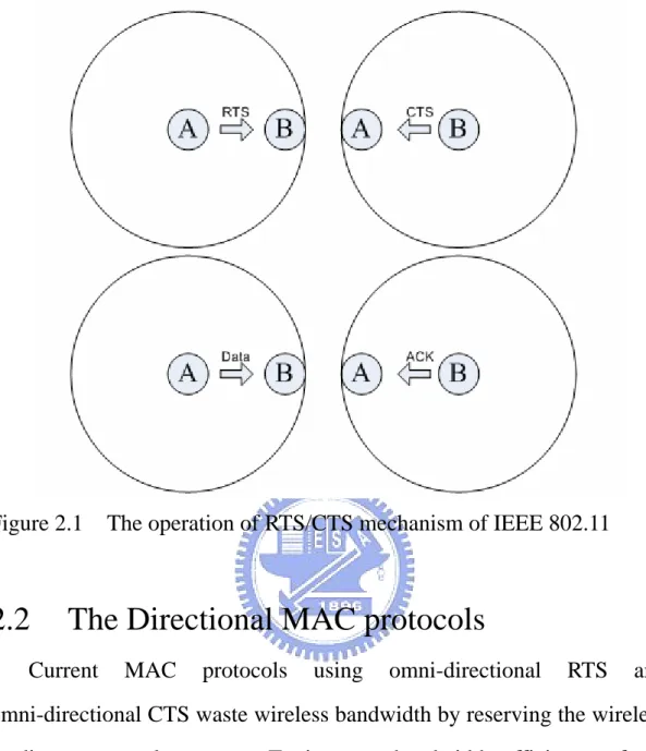
(13) increased because the contention window is double. For example, the contention window is grown like 31, 63, 127, 255, 511, and 1023. We choose a random number between zero and the contention window and the backoff time is the chosen number multiplied by the timeslot. Until the end of the backoff, it can retransmit RTS. If the timer for this RTS still expires, the contention window and the backoff time will increase again. In 802.11, these steps are taken because it is considered as congestion situation. There may be some nodes contend to use the channel. With Binary Exponential Backoff mechanism, it can mitigate the congested situation. Here we use a simple case to see the operation of IEEE 802.11 RTS/CTS mechanism. In Figure 2.1, Station A has a packet to send to Station B. First Station A sends a Request to Send (RTS) control packet to Station B. Upon receiving the RTS packet, Station B sends a Clear to Send (CTS) control packet back to Station A. If Station A receives CTS from Station B successfully, it can send the data packet. Then, if Station B receives data packet successfully, it sends an Acknowledge (ACK) back to Station A.. 10.
(14) Figure 2.1. 2.2. The operation of RTS/CTS mechanism of IEEE 802.11. The Directional MAC protocols. Current. MAC. protocols. using. omni-directional. RTS. and. omni-directional CTS waste wireless bandwidth by reserving the wireless medium over a large area. To improve bandwidth efficiency of the previous MAC protocols, there are some RTS/CTS based Directional MAC protocols [9] [10] [11] proposed, utilizing the directional transmission capability of directional antenna. We discuss them below.. 2.2.1 Dir-RTS and Omni-CTS The MAC [9] is one of the first efforts to adapt the 802.11 MAC protocol for directional antennas. The main feature of this paper is that they use directional RTS to relieve the exposed terminal problem.. 11.
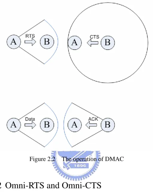
(15) The key point to note in this scheme is that, when using directional antennas, while one directional antenna at some station may be blocked, other directional antennas at the same station may not be blocked, allowing transmissions using the unblocked antennas. Here is an example of DMAC. In Figure 2.2, assume that Station A has a data packet for Station B, and assume that no other data transfers are in progress (so none of the antennas is blocked). In this case, Station A sends a directional RTS in the direction of Station B. If Station B receives the directional RTS packet from A successfully, it then returns an omni-directional CTS reply. The location information is included in the omni-directional. CTS. packet:. location. of. the. Station. sending. omni-directional CTS (Station B's location in Figure 2.2) and location of the sender of the corresponding directional RTS packet (Station A in Figure 2.2). After the successful exchange of directional RTS and omni-directional CTS packet, a data packet is sent by Station A using a directional antenna. When Station B receives the data packet, it immediately sends an ACK to Station A using a directional antenna.. 12.
(16) Figure 2.2. The operation of DMAC. 2.2.2 Omni-RTS and Omni-CTS The other protocol proposed by Nasipuri [10] uses an RTS/CTS exchange similar to that in 802.11 for enabling the source and destination nodes to identify each other’s directions. The transceiver in each node is assumed equipped with M directional antennas. The M antennas in each node are fixed with non-overlapping beam directions. When receiving on all antennas, the receiver uses the direction of the antenna that receives the maximum power of the signal as the direction of the sender. In Figure 2.3, station A wanting to send a data packet to station B, first transmits an RTS packet to station B. This is transmitted on all 13.
(17) antennas of station A, as it does not know the direction of station B at the start. If station B was in standby and receives the RTS packet correctly, it responds by transmitting a CTS packet, again on all directions (antennas). However, station B notes the direction from which it received the RTS packet by noting the antenna that received the maximum power of the RTS packet. Similarly station A estimates the direction of station B while receiving the CTS packet, and if the RTS-CTS handshake is performed successfully, proceeds to transmit the data packet on the antenna facing station B. All the neighbors of station A and station B, who hear the RTS-CTS dialog, use this information to prevent interfering with the ongoing data transmission. It is noted that when station B receives data packets from station A successfully, it does not transmit ACK back to station A. It is a place different from 802.11.. 14.
(18) Figure 2.3. The operation of the scheme in [10]. This protocol has the benefit from RTS/CTS exchange for avoiding hidden terminal problem. However, it still has the problem of exposed terminal problem because the omni-directional use of control packets. It does not gain the advantage of spatial reuse from directional transmission.. 2.2.3 Dir-RTS and Dir-CTS In DVCS [11], the main capability added to the original 802.11 MAC protocol is AOA (Angle of Arrivals) cache. Each station caches estimated AOAs from neighboring stations when it hears any signal, regardless of whether the signal is sent to the station. When the sender wants to send data to one of its neighbor, if AOA information for the neighbor has been 15.
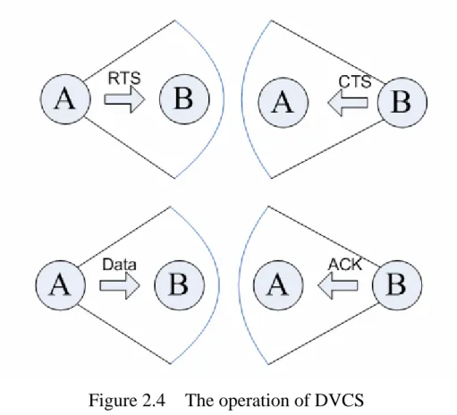
(19) cached, it beamforms the underlying directional antenna in that direction to transmit the RTS; otherwise the control packet is transmitted omni-directionally. Then, the ongoing CTS packet, Data packet and ACK are performed directionally according to the AOA cache. (See Figure 2.4). Figure 2.4. The operation of DVCS. The network throughout of this protocol increase 3-4 times compared to 802.11 because the advantage of spatial reuse. However, this protocol does not address deafness problem.. 2.3. Solutions for the deafness problem. With directional transmission, it has deafness problem because directional transmission cannot inform all of sender’s neighbors about the ongoing transmission. So some MAC protocols [12] [13] [14] are 16.
(20) proposed to mitigate the deafness problem. We discuss them as follows.. 2.3.1 The Tone DMAC The Tone DMAC [12] performs directional transmission for all control packets and data packets, and does not try to inform its neighbor about its intended communication. However, once the transmission is over, the sender and receiver transmit out-of-band tones to inform their neighbors about the end of the transmission (See Figure 2.5). Tones are transmitted omni-directionally. On detecting the tone, the neighbor that had been failing to establish communication with sender or receiver cancels its remaining backoff and starts a new one (See Figure 2.6). In 802.11, a station that does not receive CTS in reply to its RTS performs the backoff algorithm thus aggravate deafness problem. This protocol provides a scheme to reduce effects of deafness, but it needs to split channel to transmit out-of-band tones.. 17.
(21) Figure 2.5. The operation of ToneDMAC. Figure 2.6. The timeline of ToneDMAC. 18.
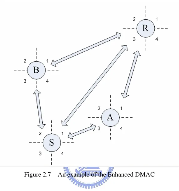
(22) 2.3.2 The Enhanced DMAC The Enhanced DMAC [13] tries to alleviate deafness problem another way. Each station maintains a neighbor transmission table (NTT) for all ongoing transmissions in its neighborhood. The NTT stores the address of the source station, which sent the RTS and the duration of the corresponding transmission. As for the CTS, the protocol has made one modification to its header. CTS now include the sender address too. According to the information from NTT, a station can decide whether to send RTS packet or not. Before sending RTS, a station uses NTT to determine if its destination is deaf or not. If is, it has to defer RTS, because the destination probably will not send back CTS. In Figure 2.7, Station A has a packet for Station B. Station A checks if Antenna (B, A) = Antenna (B, S). That is, there is an ongoing transmission between Station B and Station S. Station A and Station S are both in the direction of Antenna 4 of Station B and cannot be received simultaneously by Station B. This prevents unwarranted transmissions of RTS from station A.. 19.
(23) Figure 2.7. An example of the Enhanced DMAC. This protocol proactively tries to reduce precautionary deafness at the receiver. However, this protocol needs to modify the 802.11 packet format.. 2.3.3 The Circular RTS The Circular RTS [14] is also based on RTS/CTS exchange scheme. RTS is transmitted in all directions, but one at a time in a circular way, until it scans all the area around the sender. The neighbor uses this circular RTS to decide for its transmission differentiation in order not to destroy the ongoing transmission. This method let the source’s vicinity be informed about the intended transmission. 20.
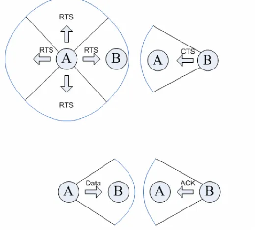
(24) For example, in Figure 2.8, Station A has a data packet for Station B. First Station A transmits duplicate RTS packets to four directions one at a time in its four antennas. Upon receiving the RTS packet, the neighbor sets its Network Allocation Vector (NAV) and suspends transmission in this period. If one of Station A’s neighbor has a data packet to send in this period, it waits until the timer of the NAV expires. This way it can prevent the deafness problem from happening around the Station A. Then, as receiving the RTS packet, Station B sends back the CTS packet directionally and the Data packet and ACK are sent directionally.. Figure 2.8. The operation of Circular RTS. 21.
(25) This protocol provides strong decrease in the hidden terminal problem and relieves the deafness problem around the sender by transmitting circular RTS, but it still has deafness problem around the receiver. In addition, it has too much overhead due to the circular RTS packets. Our proposed approach is compared with this scheme, but we do not need as much control packets to inform neighbors. We will discuss it in the next chapter.. 22.
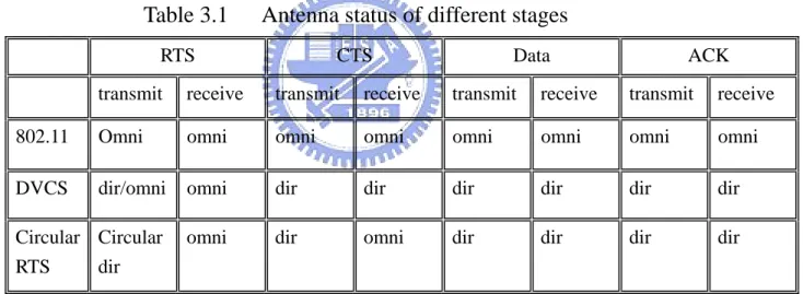
(26) Chapter 3 Pre-notification approach In this chapter, we introduce pre-notification approach to solve deafness problem in wireless ad hoc networks. First, we compare different radio models and observe the antenna status in different stages. Then, a more realistic radio model is presented. Based on this radio model, we proposed a pre-notification approach to solve deafness problem. In our approach, two parts in 802.11 MAC protocol are modified. One is RTS/CTS exchange scheme. The other is Binary exponential backoff (BEB) mechanism.. 3.1 The radio mode of transmission First, we introduce antenna model. In IEEE 802.11, antenna model is always in omni-directional mode whenever it transmits or receives a control or data packet. In DVCS, sender sends RTS directionally if it has location information about the receiver, otherwise it sends an omni-directionally RTS. Therefore, in RTS transmission stage the antenna of the sender may be one of the two modes – omni-directional or directional. The antenna of the receiver is in omni-directional mode to receiver RTS. After sending or receiving RTS packet, the station changes its antenna mode to directional mode. It means that initially the antenna is in omni-directional mode. After sending or receiving RTS packet, it changes to directional mode. It returns to omni-directional mode after 23.
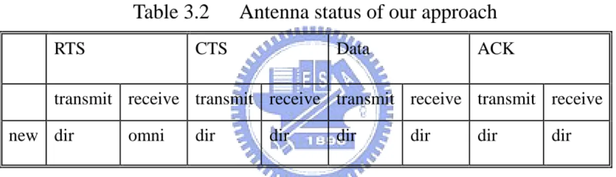
(27) sending or receiving the Ack. In Circular Directional RTS, it transmits RTS to all directions one at a time in a circular way. Different from DVCS, sender receives CTS omni-directionally. Then it performs packet transmission directionally until the end of the transmission. That is, the antenna is in omni-directional mode at the start. The sender sends circular RTS directionally and then changes to omni-directional mode to receive CTS from its receiver. After receiving CTS, it switches to directional mode. The receiver changes to directional mode after it receives RTS packet omni-directionally. Table 3.1 shows the antenna status of different stages in detail.. Table 3.1. Antenna status of different stages. RTS. CTS. Data. ACK. transmit. receive. transmit. receive. transmit. receive. transmit. receive. 802.11. Omni. omni. omni. omni. omni. omni. omni. omni. DVCS. dir/omni. omni. dir. dir. dir. dir. dir. dir. Circular Circular RTS dir. omni. dir. omni. dir. dir. dir. dir. In our scheme, antenna model is in omni-directional mode initially. If it needs to transmit RTS or CTS packet, it changes to directional mode. Then it switches back to omni-directional mode until the end of the transmission. We use this scheme to separate deafness situation from congestion situation. That is, before the end of RTS omni-receiving stage, station can receive RTS packets from any direction. These RTS packets are considered to contend the channel and the loser of the contention will 24.
(28) follow steps of our approach. After the RTS omni-receiving stage, station changes to directional transmitting and directional receiving mode. It does not receive any packet besides its intended receiver. Before the end of the transmission, the station may have other RTS for it. However, it cannot receive them and the senders of these RTS packets are regarded as sending packet to a busy station. Then these stations obey the IEEE 802.11 MAC protocol to do backoff operations. From the antenna status of our approach (See Table 3.2), we define deafness situation. Next section we give details of our approach to deal with deafness situation.. Table 3.2 RTS. Antenna status of our approach. CTS. Data. ACK. transmit receive transmit receive transmit receive transmit receive new dir. omni. dir. dir. dir. dir. dir. dir. 3.2 Pre-notification CTS packet In this section, we modify RTS/CTS exchange scheme such that the situation of deafness is separated from congestion. In IEEE 802.11, Station A and Station C may try to send packet to Station B at the same time (Figure 3.1). Station A’s RTS arrives at Station B before Station C’s RTS. Then Station B chooses Station A as the winner of the contention and sends CTS packet to Station A. Station C does backoff operation and does the next contention until the end of the backoff (Figure 3.2). In 802.11, it does Binary Exponential Backoff to 25.
(29) alleviate congestion situation.. Figure 3.1. Figure 3.2. The operation of IEEE 802.11. Timeline of IEEE 802.11. When using directional transmission, it causes deafness problem. So in our approach, upon receiving RTS from Station A and Station C (Figure 3.3), we send back CTS to both of them (Figure 3.4). We do not send duplicate CTS packets to them, but original CTS to each of them. Avoiding causing all of them sending data packets to station B, we require a modification here. We change the content of the CTS packets that are sending back to the losers of the contention (in this case: Station C). We change the duration time of the CTS packet to zero. Thus, according to the field of the duration time we can use CTS packets to 26.
(30) inform these contending stations about the deafness circumstance.. Figure 3.3. The operation of RTS stage. Figure 3.4. The operation of CTS stage. 3.3 Modified backoff mechanism In this section, we describe another modification. In section 3.2, we send CTS packets back to stations that have sent RTS packets before. We send CTS packets that duration time setting to zero back to stations that 27.
(31) lose in the contention period. Stations receiving CTS packets check if duration time equals to zero or not. If so, it does not increase its backoff time and after the chosen backoff time it retransmits RTS packet (Figure 3.5). That is, we consider it as deafness situation and these stations do not follow binary exponential backoff scheme. If duration time does not equal to zero, the station sends data packet and then it follows the steps of 802.11.. Figure 3.5. The timeline of our approach. 28.
(32) Chapter 4 Simulation In this chapter, we simulate our pre-notification approach to solve deafness problem. We use NS2 [15] as our simulation environment. Because the network simulator does not have components about directional antenna, we use the directional antenna model in The Enhanced Network Simulator (TeNs) designed by Kumar and Roy [16]. TeNs is an attempt to address the deficiencies of NS2 in the modeling of IEEE 802.11 MAC layer protocol.. In section 4.1, we design a simple. deafness problem case to compare difference between Circular RTS, directional transmission without pre-notification approach (Directional IEEE 802.11) and our proposed method (Pre-notification approach). In section 4.2, we vary the packet size to observe the overall time needed and throughput at different data rates. In section 4.3, we vary the number of contending stations to see the effect when the network environment becomes more dense and congested. At last, we design a simple linear topology to see a multi-hop case in section 4.4.. 4.1. A simple deafness case In this section, we devise a simple deafness problem environment.. Figure 4.1 shows that Station 0 transmits UDP per second to Station 1 from timeslot 5 to timeslot 35 and Station 2 transmits UDP per second as well to Station 1 from timeslot 15 to timeslot 45. Packet size is a constant about 2500 bytes. 29.
(33) Figure 4.1. The topology of our simple case. Figure 4.2 shows the result of Figure 4.1. The X-axis is the timeslot from timeslot 5 to timeslot 45. The Y-axis is the overall time needed to complete transmissions at that timeslot. That is, from timeslot 5 to timeslot 15, it is recorded the required time Station 0 transmits a UDP to Station 1 from sending out RTS until the reception of ACK. From timeslot 35 to timeslot 45, it is the same for the session Station 2 transmits a UDP to Station 1. From timeslot 15 to timeslot 35, the two transmissions process parallel and cause deafness problem.. 30.
(34) 12000 Circular RTS Directional IEEE 802.11 Pre-notification approach. 11000. time needed *10-6 (sec). 10000 9000 8000 7000 6000 5000 4000 3000. 5. 10. Figure 4.2. 15. 20. 25 timeslot. 30. 35. 40. 45. The successful transmission time of Figure 4.1. In the period of single transmission, Circular RTS costs more 1086 * 10-6 seconds to complete and about 33.95% compare to the other two methods. It is because Circular RTS needs to transmit RTS circularly around the sender before each packet transmission. In our experiment, Circular RTS needs to transmit in its four antennas one at a time and informs its neighbor about the ongoing transmission. Directional IEEE 802.11 and our Pre-notification approach cost the same because there is no deafness situation under single transfer. In the time from 15 to 35, Circular RTS costs average of 10288.16*10-6 seconds to complete the two sessions. Directional IEEE 802.11 costs about 8182.474*10-6 seconds and decreases about 26% 31.
(35) compare to Circular RTS. Pre-notification approach needs about 7231.947*10-6 seconds and reduces 42% and 13% of time compare to Circular RTS and Directional IEEE 802.11. 70 Circular RTS Directional IEEE 802.11 Pre-notification approach. chosen contention window. 60. 50. 40. 30. 20. 10. 0. 5. 10. Figure 4.3. 15. 20. 25 timeslot. 30. 35. 40. 45. The chosen contention window of Figure 4.1. From Figure 4.3, we can see each contention window chosen in each timeslot from time 15 to 35. Directional IEEE 802.11 shows more variance compare to Pre-notification approach because it does Binary Exponential Backoff (BEB) before retransmitting RTS.. 4.2. Variable packet size In this section, we vary the packet size in the case of Figure 4.1. We. change UDP packet size from 625 bytes to 5000 bytes to record the time 32.
(36) needed to complete the transmission from time 15 to 35. It shows from Table 4.1 that as packet size increases, it needs more time to transmit a data packet. However, from 625 bytes case to 5000 bytes case, difference between three methods are about the same (See Figure 4.4).. 14000 13000. time needed *10-6 (sec). 12000 11000 10000 9000 8000 7000 6000. Circular RTS Directional IEEE 802.11 Pre-notification approach. 5000 4000 500. 1000. Figure 4.4. 1500. 2000. 2500 3000 3500 packet size (bytes). 4000. 4500. 5000. The successful transmission time of different packet size. Table 4.1. The table of Figure 4.4 (*10-6 sec). 625 (bytes) 1250(bytes) 2500(bytes) 5000(bytes) Circular RTS. 7366. 8470. 10288. 13926. Directional IEEE 802.11. 5455. 6364. 8226. 11819. Pre-notification approach. 4505. 5414. 7232. 10869. 33.
(37) Now, we use the case of Figure 4.1 as well, but change the traffic from Constant Bit Rate (UDP) to TCP. Packet size is also a constant about 2500 bytes. Two sessions send TCP traffic simultaneously for 10 seconds. In Figure 4.5, the X-axis is the data rate from 200k bit per second to 2600k bit per second (2.6Mbps). The Y-axis is the throughput, which means the number of TCP packets received successfully. When sending in 200k bps, three methods perform about the same. However, as data rate increases, Circular RTS gets worst performance. It is because the overhead of Circular RTS is too high. In addition, the Directional IEEE 802.11 and the Pre-notification approach perform almost the same regardless of data rate. We can conclude that our proposed method does not adapt to environment of continuous traffic. However, it still performs as good as original backoff method.. 34.
(38) 1600 1400. throughput (*2500bytes). 1200 1000 800 600 400 Circular RTS Directional IEEE 802.11 Pre-notification approach. 200 0. 0. 500. Figure 4.5. 4.3. 1000. 1500 Data rate (kbs). 2000. 2500. 3000. The throughput of different data rate. Variable number of contending stations In this section, we vary the number of contending stations. In Figure. 4.6, compare to the case in Figure 4.1, we add another two stations – Station 3 and Station 4. We increase the number of contending stations from 1 to 4 and record the required time to transmit a 2500 bytes UDP packet per second from all contending stations.. 35.
(39) Figure 4.6. The topology of variable contending stations. In Figure 4.7, the X-axis means the number of contending stations. In our simulation, X=1 means there is just Station 0 transmits packet to Station 1. X=2 means Station 0 and Station 2 transmit packet to Station 1 simultaneously. X=3 means Station 3 attends the contention and X=4 means Station 4 does the same operation as other three stations. The Y-axis means the overall time needed to complete all attending transmissions. From Figure 4.7 and Table 4.2, we can see that as the number of contending stations increases, Circular RTS needs more much time to complete. The difference between Circular RTS and the other two becomes larger as the number of contending stations increases. Comparing Directional IEEE 802.11 method and Pre-notification approach method, as number of stations increases, Pre-notification 36.
(40) approach performs better than the Directional IEEE 802.11. This means, as network environment becomes dense, Pre-notification approach provides better operation to handle deafness problem.. Figure 4.7. The successful transmission time of different number of contending stations. Table 4.2. The table of Figure 4.7 (*10-6 sec). Number of contending. 1. Stations. 2. 3. 4. Circular RTS. 4282. 10288. 15645. 21118. Directional IEEE 802.11. 3196. 8177. 11654. 16474. Pre-notification approach. 3196. 7232. 10632. 14636. 37.
(41) 4.4. A multi-hop case In this section, we simulate a simple multi-hop case. See Figure 4.8,. there is five stations in this linear topology. Station 0 sends FTP packets fixed to 2500 bytes to Station 4 in 100 sections. We use AODV as our routing protocol.. Figure 4.8 the topology of multi-hop case. In Figure 4.9, the X-axis means the different data rates. The Y-axis means the throughout successfully received at Station 4.. throughput (*2500bytes). 15000. 10000. 5000 Circular RTS Directional IEEE 802.11 Pre-notification approach. 0. 0. 500. 1000. 1500 2000 Data rate (kbps). 38. 2500. 3000.
(42) Figure 4.9. the throughput of different data rate. From Figure 4.9, we can see that as data rate increases, our approach performs better than Circular RTS and performs as good as Directional IEEE 802.11. This result means that our approach does not increase too much overhead in a multi-hop wireless network.. 39.
(43) Chapter 5 Conclusion and future work. In this thesis, we propose a pre-notification approach to solve deafness problem in wireless ad hoc networks. Our methods modify IEEE 802.11 MAC protocol in two places. First, we change the RTS/CTS exchange scheme. We use CTS packet with duration time equals to zero to inform the defer stations that the receiver is deaf to them. Then, as receiving these pre-notification CTS packets, stations do not do Binary Exponential Backoff (BEB) but maintain a fixed Backoff timer. By this way, we can reduce channel idle time. Simulation results show that our scheme is suitable for the network with directional antennas and perform better as the network becomes dense. In order to increase the effectiveness, we plan to include the hidden terminal problem and the exposed terminal problem to gain full benefit from directional transmission.. 40.
(44) References [1]. IEEE 802.11 Working Group. Wireless LAN Medium Access Control (MAC) and Physical Layer (PHY) Specifications, 1999 [2]. J. Deng and Z. J. Haas, "Dual Busy Tone Multiple Access (DBTMA): A New Medium Access Control for Packet Radio Networks," in IEEE ICUPC'98, Florence, Italy, October 5-9, 1998. [3]. A. Acharya, A. Misra, and S. Bansal, "MACA-P: A MAC for Concurrent Transmissions in Multi-Hop Wireless Networks," Proceedings of the First IEEE International Conference on Pervasive Computing and Communications, p.505, March 23-26, 2003. [4]. N. Poojary, S. V. Krishnamurthy, and S. Dao, "Medium Access Control in a Network of Ad Hoc Mobile Nodes with Heterogeneous Power Capabilities," Proceedings of IEEE ICC 2001, vol.3, pp.872-877, June 2001. [5]. V. Shah, S. Krishnamurthy, and N. Poojary, "Improving the MAC Layer Performance in Ad Hoc Networks of Nodes with Heterogeneous Transmit Power Capabilities," IEEE ICC'04, Vol. 7, pp. 3874 - 3880, Jun. 2004. [6]. K.Xu, M.Gerla, and S.Bae, "How Effective is the IEEE 802.11 RTS/CTS Handshake in Ad Hoc Networks," In Proceedings of IEEE GLOBECOM'02, November 2002. [7]. H.-J. Ju, I. Rubin, and Y.-C. Kuan, "An Adaptive RTS/CTS Control Mechanism for IEEE 802.11 MAC Protocol," IEEE Vehicular Technology Conference, Vol. 2, pp. 1469 – 1473, 2003. [8]. Z.N. Kong, D. Tsang and B. Bensaou, "Adaptive RTS/CTS Mechanism for IEEE 802.11 WLANs to Achieve Optimal Performance," IEEE International Conference on Communications (ICC'04), Paris, France, June 2004. [9]. Y.-B. Ko, V. Shankarkumar, and N. H. Vaidya, "Medium Access Control Protocols Using Directional Antennas in Ad Hoc Networks," in IEEE INFOCOM 2000, Mar. 2000. [10]. A. Nasipuri, S. Ye, J. You, and R. E. Hiromoto, "A MAC Protocol for Mobile Ad Hoc Networks Using Directional Antennas,'' in Proc. of the IEEE Wireless Comm. and Networking Conf. (WCNC) 2000, (Chicago, IL, USA), Sept. 2000. [11]. M. Takai, J. Martin, A. Ren, and R. Bagrodia, "Directional Virtual Carrier Sensing for Directional Antennas in Mobile Ad Hoc Networks,'' in ACM MobiHoc '02, (Lausanne, Switzerland), June 2002. [12]. R. Choudhury and N. Vaidya, "Deafness: A MAC Problem in Ad Hoc Networks 41.
(45) when using Directional Antennas," in Proceedings of IEEE International Conference on Network Protocols (ICNP’04), Berlin, Germany, pp. 283-292, October 2004. [13]. H. Gossain, C. M. Cordeiro, D. Cavalcanti, and D. P. Agrawal, "The Deafness Problems and Solutions in Wireless Ad Hoc Networks using Directional Antennas," IEEE Workshop on Wireless Ad Hoc and Sensor Networks, in conjunction with IEEE Globecom, November 2004. [14]. T. Korakis, G. Jakllari, L. Tassiulas, "A MAC Protocol for Full Exploitation of Directional Antennas in Ad-hoc Wireless Networks," in ACM Mobihoc, June 2003. [15]. NS-2 Network Simulator. http://www.isi.edu/nsnam/ns/index.html. [16]. The Enhanced Network Simulator (TeNs). http://www.cse.iitk.ac.in/~bhaskar/tens/index.html.. 42.
(46)
數據

![Figure 2.3 The operation of the scheme in [10]](https://thumb-ap.123doks.com/thumbv2/9libinfo/8135988.166431/18.892.144.754.115.747/figure-operation-scheme.webp)
+7
相關文件
• 利用資訊科技解決問題:停課期間,學校利 用Zoom視像教學,並以Google Classroom作
協作 溝通 創造 批判性思考 運用資訊科技 運算 解決問題 自我管治 研習. 中一
• Also known as glossy, rough specular and directional diffuse reflection. directional
(2) We emphasized that our method uses compressed video data to train and detect human behavior, while the proposed method of [19] Alireza Fathi and Greg Mori can only
Secondly then propose a Fuzzy ISM method to taking account the Fuzzy linguistic consideration to fit in with real complicated situation, and then compare difference of the order of
此外,由文獻回顧(詳第二章)可知,實務的車輛配送路線排程可藉由車 輛路線問題(Vehicle Routing
無線感測網路是個人區域網路中的一種應用,其中最常採用 Zigbee 無線通訊協 定做為主要架構。而 Zigbee 以 IEEE802.15.4 標準規範做為運用基礎,在下一小節將 會針對 IEEE
Our preliminary analysis and experimental results of the proposed method on mapping data to logical grid nodes show improvement of communication costs and conduce to better
