Automatic Learning and Guidance for Indoor
Autonomous Vehicle Navigation by Ultrasonic
Signal Analysis and Fuzzy Control Techniques
Mei-Fen Chen (陳梅芬)
Inst. of Multimedia Eng., National Chiao Tung University, Hsinchu, Taiwan 30010
Email: kirisame.cs96g@nctu.edu.tw
Wen-Hsiang Tsai (蔡文祥)
Dept. of Computer Science, National Chiao Tung University, Hsinchu, Taiwan 30010
Email: whtsai@cis.nctu.edu.tw
Abstract―An intelligent autonomous vehicle system for path learning and navigation guidance in corridor environments is proposed, which has the capabilities of learning paths by person following, interaction with humans, path analysis, and navigation as a guide. To learn paths automatically and conveniently, a method for person following is proposed, which uses two fuzzy controllers for following a person dynamically. Next, a method for path analysis is proposed, which analyzes the learned path data to estimate turning parameters for navigation. Also, a method for vehicle navigation guidance using ultrasonic signal sequences and a fuzzy controller is proposed. The main feature used for navigation is wall. Finally, experimental results are shown to prove the flexibility and feasibility of the proposed system.
Index Terms―autonomous vehicle navigation,
ultrasonic signal, fuzzy control, automatic learning, guidance.
I. INTRODUCTION
In recent years, autonomous vehicles have more and more applications. When we visit an office in a building or an exhibition, we usually desire some guidance to introduce the environment to us. The most common way is to set up guide signs or to provide tour guides, but these measures sometimes may not be convenient. This problem may be solved if we can use an autonomous vehicle to follow a learned guidance map and act as a guide.
To learn a guidance map, it is desired that an autonomous vehicle have the abilities of following a person, as well as recording and organizing the routes of the person as a map in the mean time. To achieve the mission of person following in indoor environments, many studies adopted the vision-based approach and used cameras as sensors. Wang and Tsai [1] proposed a method for person following, which uses an elliptic skin model to
detect human faces by color and shape features in images. Tsai and Tsai [2] proposed a method for the same purpose in environments where the luminance is not uniform. In addition, Ku and Tsai [3] proposed a sequential pattern recognition method to decide the location of a person with respect to a mobile robot and detect a rectangular shape attached on the back of the person to achieve smooth person following.
Additionally, there have been many researches on using fuzzy logic control techniques for navigation control of autonomous vehicles or mobile robots. Peri and Simon [4] proposed a fuzzy control method to control an autonomous wall-following robot equipped with ultrasonic sensors. The robot can navigate along a predefined path. Xin, et al. [5] proposed a fuzzy control method for an unmanned exploration vehicle equipped with ultrasonic sensors. They used a fuzzy logic algorithm to fuse the vehicle’s behaviors and self-tuning membership functions to control the vehicle. Datta, et al. [6] proposed a method for mobile robot localization using laser-based maps, and a fuzzy controller for obstacle avoidance. Islam, et al. [7] proposed a fuzzy controller to guide a mobile robot to navigate in unstructured environments and avoid obstacles without human intervention.
The goal of this study is to design an intelligent autonomous vehicle system for path learning by
person following and for navigation control by ultrasonic sensors in corridor environments.
Convenience in the learning process is the major concern, for which a totally automatic scheme is proposed a person just walks through the desired
route in front of the vehicle without touching the
vehicle system and the vehicle will collect and organize the along-route information through ultrasonic sensing and fuzzy control techniques as a path map for later use in the navigation stage using fuzzy control techniques as well. The details will be introduced in the following sections, with the system configuration described in Section II, the learning process in Section III, the path analysis process in Section IV, the navigation process in Section V, some experimental results in Section VI, followed by some conclusions in the last section.
II. SYSTEM CONFIGURATION
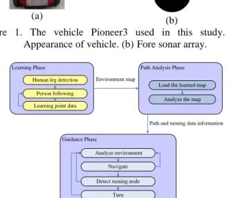
In the proposed vehicle system, a Pioneer 3, which is a vehicle made by ActiveMedia Robotics Technologies, Inc., is used as a test bed. A diagram illustrating its configuration is shown in Fig. 1.
The overall framework of the proposed system with four capabilities is illustrated in Fig. 2. Several methods have been proposed to deal with various works required in the system. The first is proposed for person following using ultrasonic sensors and fuzzy logic control techniques. To follow a person, the vehicle detects the person’s leg and computes accordingly the distance between the person and itself. To decide whether the distance obtained from the sonar is smaller than that between the vehicle and the person, we assume the person is the nearest one in front of the vehicle. Therefore, if the distance obtained from the sonar in front of the vehicle is smaller than a threshold, it is used as the distance between the vehicle and the person. The second method is proposed for path analysis, in which the vehicle analyzes the record obtained in the learning phase by applying the first method to get some guiding information, including wall widths in environments, when to turn, when to introduce objects, etc. The third method is proposed for controlling the vehicle by ultrasonic sensors and fuzzy logic control techniques to navigate as a guide in corridor environments. This method deals with four major stages in the navigation process. The first is environment analysis in which the vehicle analyzes the signal detected from the ultrasonic sensor. In the second stage, the analysis result and as well as some fuzzy logic control techniques are combined to navigate the vehicle. In the third stage, whether the vehicle has arrived at a
turning node or not is decided. If so, then the vehicle is instructed to turn in the fourth stage.
III. LEARNING PROCEDURE
3.1. Learning of Path Data
While the proposed vehicle follows a person, it learns path data in the mean time. For this, the proposed system is designed to obtain four kinds of information from different sources, as identified in this study. They are: (1) the speed of the vehicle provided by the odometer, (2) the running time of the program which controls the vehicle provided by the computer, (3) the distance with respect to surrounding objects and walls provided by the ultrasonic sensors, and (4) the command with regard to the surrounding environment provided by the person. The ultrasonic sensors equipped in the vehicle include fore and aft sonar arrays. The sonar positions in the on-board sonar array are fixed: one on each side and six facing outward at 20-degree intervals. The fore sonar array is shown in Fig. 1(b). The command information describes the ways the person interacts with the vehicle in the learning process. For example, if the vehicle detects that the person stops, it stops, too. In other words, the command information is not obtained via key-in operations by the person as done in the traditional human-involving approach. (a) 1 2 3 4 5 6 0 Front 7
Left No.4, Right
10° No.5, 30° No.6, 50° No.7, 90° No.2, -30° No.3, -10° No.1, -50° No.0, -90° (b)
Figure 1. The vehicle Pioneer3 used in this study. (a) Appearance of vehicle. (b)Fore sonar array.
Path Analysis Phase Learning Phase
Human leg detection Person following Learning point data
Guidance Phase
Analyze environment Environment map
Path and turning data information
Navigate Detect turning node
Turn
Load the learned map Analyze the map
3.2. Proposed fuzzy controller for controlling
vehicle direction
The sonar positions in the sonar arrays shown in Fig. 1(b) are not directly in front of the vehicle. Therefore, if the vehicle moves straight and follows a person as shown in Fig. 3(a), it cannot detect the person by ultrasonic sensors correctly all the time. However, if it moves on a curve path as shown in Fig. 3(b) or 3(c), detection of the person by ultrasonic sensors will be more effective. More specifically, in order to keep following the person all the time, the vehicle has to move in a way of keeping the person’s position directly in front of it. However, the vehicle may move on a curve trajectory because of incremental mechanic errors or because the person does not walk on a straight path. For this, if the vehicle detects that the person is on the left-hand side of it as shown by Fig. 3(b), then the vehicle knows that the person is moving on a curve path and adjusts its direction by turning left. Similarly, if the vehicle detects that the person is on the right-hand side of it as shown by Fig. 3(c), then it adjusts its direction by turning right. In addition, in order to improve the chance to detect the person by ultrasonic sensors, the values detected from ultrasonic sensors No. 2, 3, 4, and 5 are used as the inputs to a fuzzy controller proposed in this study for controlling the vehicle turning angle.
(a) (b) (c)
Figure 3. Relative positions of a person and the vehicle. The arrows represent signals of ultrasonic sensors. Blue circles represent the person. (a) The vehicle moves on a straight path. (b) and (c) The vehicle moves on a curve path.
In more detail, let the control variable for the proposed fuzzy controller be denoted as ANGLE, which represents the angle of the required vehicle’s turning. The input variables to the controller are denoted as D2, D3, D4, and D5, which represent the
values measured from ultrasonic sensors No. 2, 3, 4, and 5, respectively. Three fuzzy terms are defined for each input variable, namely, NE, MI, and FA,
which means near, middle, and far, respectively, to the vehicle. A membership function µA(⋅) is
specified for each of the three fuzzy terms, where A = NE, MI, and FA, as illustrated in Fig. 4.
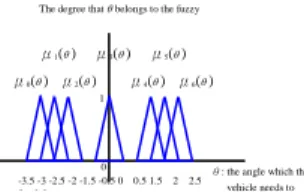
Furthermore, seven fuzzy terms are defined for the output control variable ANGLE. They are 0 through 6, meaning negative large through positive
large. The term 0(negative large) means that the
vehicle should turn a large angle to the left. Similarly, the term 6(positive large) means that the vehicle should turn a large angle to the right. A membership function ui(⋅) is specified for each of
the seven fuzzy terms where i = 0, 1, …, 6, as illustrated in Fig. 5.
Let Ak, Bk, Ck, and Ek represent the linguistic
values of the three fuzzy terms, NE, MI, and FA for each input variable D2 through D5. And let Fj
represent the linguistic value of the seven fuzzy terms of the output variable ANGLE. Accordingly, a total of 81 fuzzy rules are derived in this study for
ANGLE, which may be represented as a fuzzy rule matrix as shown in Table 1, in which the fuzzy
terms of ANGLE represented as seven values 0 through 6 is described by Table 2. Specifically, each fuzzy rule is described as:
Ri : IF D2 is Ak, D3 is Bk, D4 is Ck, AND
D5 is Ek, THEN ANGLE is Fj. (1)
Finally, it is mentioned that the method we use to defuzzify the fuzzy output is the discrete fuzzy centroid defuzzification.
Figure 4. Membership functions of three fuzzy terms, NE, MI, and FA of input variables D2 through D5.
Figure 5. Membership functions of seven fuzzy terms of output variable ANGLE.
-3.5 -3 -2.5 -2 -1.5 -0.5 0 0.5 1.5 2 2.5 3 3 5
θ: the angle which the vehicle needs to t μ0(θ ) μ1(θ ) μ2(θ ) μ3(θ ) μ4(θ ) μ5(θ ) μ6(θ ) 0 1 The degree that θ belongs to the fuzzy
The degree that d belongs to NE, MI, or FA.
μNE(d) μFA(d-)
50 90 120 cm
3.3. Proposed fuzzy controller for controlling
vehicle speed
The relationship between the person’s speed and that of the vehicle is an important factor in the proposed method. If the person walks faster than the vehicle, the vehicle should speed up, and vice versa. A fuzzy controller has been designed in this study for controlling the vehicle speed in a smooth way for this purpose, which retrieves distance information Di = (d2,i, d3,i, d4,i, d5,i) which are
measured respectively from ultrasonic sensors Nos. 2 through 5 at time instance i. The person’s speed is estimated accordingly by the two variables Di and
Di-1 measured at the two time instances i and i − 1.
Three input variables are used for this fuzzy controller, including the distance di measured at
time i (denoted as DN), the distance di-1 measured at
time i − 1 (denoted as DL), and the vehicle speed at
time i (denoted as SV). It is assumed that only one
person is in front of the vehicle. Therefore, at time i, the input value di of the variable DN is taken to be
the minimum of d2,i, d3,i, d4,i, and d5,i, and the input
value di-1 of the variable DL is taken to be the
minimum of d2,(i-1), d3,(i-1), d4,(i-1), and d5,(i-1).
However, a wall may also be in front of the vehicle when the vehicle is reaching a corner. In order to differentiate this situation from the normal one, each of DN and DL has been assigned an extra fuzzy
term to do this work, denoted as UB. If the input distance value is very large, then it must be decided that the input value belongs to this term with a large degree of possibility, because such a value cannot be used to decide what is in front of the vehicle, the person or a wall.
Table 1. Fuzzy rule matrix for controlling vehicle turning with output variable ANGLE.
Left \ Right D5 NE5 MI5 FA5
D2 D3 \ D4 NE4 MI4 FA4 NE4 MI4 FA4 NE4 MI4 FA4 NE2 NE3 3 2 2 3 2 2 3 2 2 MI3 4 3 2 4 3 1 4 3 1 FA3 4 4 3 4 5 1 4 5 0 MI2 NE3 3 2 2 3 2 2 3 2 2 MI3 4 3 1 4 3 1 4 3 1 FA3 4 5 5 4 5 3 4 5 0 FA2 NE3 3 2 2 3 2 2 3 2 2 MI3 4 3 1 4 3 1 4 3 1 FA3 4 5 6 4 5 6 4 5 3
Table 2. Terms of output variable ANGLE.
Turn left --- Straight --- Turn right
0 1 2 3 4 5 6
Six fuzzy terms are defined for each of the input variables, DN and DL. They are NE(nearer),
N(near), MI(middle), F(far), FE(farther), and UB(unbelievable), where the last term UB is as just defined. The membership functions defined for these terms are illustrated in Fig. 6. Furthermore, five fuzzy terms, SE(slower), S(slow), MD(middle), FS(fast), and FR(faster) are defined for the input variable SV. The membership functions designed
for these terms are illustrated in Fig. 7.
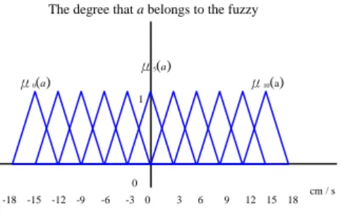
The output variable, denoted as SA, represents the vehicle speed to change. Eleven fuzzy terms are defined for it. They are 0 through 10, meaning respectively negative large through positive large. A negative value means that the vehicle has to decrease its speed. The membership functions designed for these terms are illustrated in Fig. 8.
Figure 6. Membership functions of six fuzzy terms, NE, N, MI, F, FE, and UB of input DN or DL.
Figure 7. Membership functions of five fuzzy terms SE, S, MD, FS, and FR of input variable SV.
Figure 8. Membership functions of eleven fuzzy terms of output variable SA.
-18 -15 -12 -9 -6 -3 0 3 6 9 12 15 18 μ0(a) μ5(a) μ10(a) 0 1
The degree that a belongs to the fuzzy
cm / s a: difference of the vehicle’s speeds at time i and i+1 The degree that s belongs to SE, S, MD, FS, or FR.
μSE(s) 20 30 cm / s μS(s) 40 50 60 μMD(s) μFS(s) μFR(s)
s: the speed obtained by the above-mentioned way. The degree that d belongs to NE, N, MI, F, FE, or UB.
μNE(d) 42.5 55 110 cm μN(d-) 67.5 80 92.5 μMI(d) μF(d) μFE(d) μUB(d)
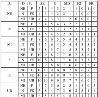
A total of 180 fuzzy rules have been designed
accordingly, which are represented as a fuzzy rule matrix shown in Table 3, and the meaning of the fuzzy terms of the output variable SA are described in Table 4.
Table 3. Fuzzy rule matrix for controlling vehicle speed.
DN DL \ SV SE S MD FS FR NE NE F 5 3 4 3 2 1 1 0 1 0 N FE 4 3 4 2 2 1 1 0 0 0 MI UB 4 4 3 3 1 2 0 0 0 0 N NE F 6 4 5 4 3 2 2 1 2 0 N FE 5 3 5 3 3 2 2 1 1 0 MI UB 4 6 4 5 2 3 1 1 1 1 MI NE F 8 6 6 5 5 4 4 3 3 2 N FE 7 5 6 4 5 4 4 3 3 2 MI UB 6 8 5 7 4 5 3 3 2 1 F NE F 10 9 8 7 7 6 7 5 6 4 N FE 10 8 8 7 7 6 6 5 5 3 MI UB 9 9 8 8 7 6 6 5 5 4 FE NE F 10 10 9 8 8 7 8 6 7 5 N FE 10 9 9 8 8 7 7 6 6 5 MI UB 10 10 9 9 8 7 7 6 6 5 UB NE F 4 7 3 6 2 5 1 4 0 3 N FE 5 8 4 7 3 6 2 5 1 4 MI UB 6 5 5 5 4 5 3 4 2 4
Table 4. Fuzzy terms of output variable SA.
SA
Decrease speed more ---Zero--- Increase speed more
0 1 2 3 4 5 6 7 8 9 10
3.4. Analysis of commands for vehicle decided by human behavior and a voting technique In this study, four kinds of commands are proposed for use by the vehicle in the path learning process, which are obtained by analyzing the ultrasonic signals and the person’s behavior. These commands are denoted as TURN, RECORD, WALK, and END. The command TURN means that the vehicle is at a turning node and it has to turn. The command RECORD means that the vehicle is at a node during navigation where it should stop to introduce something as a tout guide by playing a pre-recorded audio clip. The command WALK means that the vehicle is at a node where it has to continue to follow the person. The command END means that the vehicle is at the end of a path being learned.
Specifically, to tell the vehicle a person’s command of one of these four in each learning cycle, it is proposed in this study that the person
either walks in front of the vehicle smoothly or stand aside the vehicle motionlessly. Then, a voting technique using the ultrasonic signal readings is adopted to determine the person’s behavior, or equivalently, the type of the command issued by the person. In this voting scheme, the values of all the ultrasonic sensors are acquired for a pre-defined number of times, say n. And in each time, the sensor among the front ones (Nos. 0 through 7) which receives a significant signal (with a reasonable distance value) will be detected, and is said to receive a vote. For example, if the person stands in front of the vehicle, the signal value of sensor No. 3 or 4 will be read to be significant and the command WALK (meaning “walk” in front of the vehicle) will get a vote. Finally, the command which gets a sufficiently-large number of votes in the n times of signal readings is determined to be the real command issued by the person. If no sufficient number of votes can be collected, then the command is decided to be END. The positions where the person stands on around the vehicle and the respective mapping commands are illustrated in Fig. 9. No.4, 10° No.5, 30° No.6, 50° No.7, 90° No.2, -30° No.3, -10° No.1, -50° No.0, -90° No . 8 No . 15 TURN TURN TURN TURN TURN TURN WALK WALK RECORD RECORD
Figure 9. Illustration of around-vehicle positions where the person stands on and their respective mapping commands.
IV. AUTOMATIC PATH ANALYSIS
When the vehicle learns path data by following a person, the trajectory of the path may not be straight, but curvilinear, most of the time. Therefore, it is desired that the vehicle can plan a navigation path to visit all the objects which it has to introduce as a tour guide without hitting the walls in the environment. To this aim, the path data collected in this study for such a navigation mission include five kinds of information: (1) when to turn, denoted by TTURN; (2) the distance between walls in the
environment, denoted by WDIS; (3) the intolerable
distance between the vehicle and an obstacle in front of the vehicle, denoted by IDIS; (4) when to stop, denoted by TSTOP; (5) when to introduce objects or places as a tour guide, denoted as
TOBJECT. The last three kinds of information can
be obtained from the learned data easily. Therefore, we describe how to obtain the first two kinds of information in the following.
4.1. Turning
To obtain the information TTURN correctly, let the distance from a turning corner to the turning node be denoted as Dturn. Then, presumably the
vehicle should detect very large distance values by its ultrasonic sensors on a turning direction from the position of the turning corner to that of the turning node. Therefore, we can obtain the value of
Dturn by computing the recorded information of its
running time and speed from the turning node back to the starting position of the turning corner. However, the vehicle may also detect very large distance values by its ultrasonic sensors before arriving at the turning corner, for example, at a spot where a door is opened, or where there includes more than one crossroad, etc. In order to obtain correct information for a real turning corner, the strategy used in this study is to create an extract node to tell the vehicle not to turn at this node before arriving at the real turning corner.
4.2. Computing distances between walls
The idea proposed for computing the distance d between the two side walls at a spot in a corridor is to compute d as the sum of the detected values from ultrasonic sensors on the left- and right-hand sides of the vehicle when the vehicle moves in parallel with walls. Several steps have been designed to implement this idea. The first is to make a rough estimate of the wall distance at each node in the path as the sum of the detected values from the ultrasonic sensors on the left- or right-hand sides of the vehicle and refined the estimate later. The second step is to make sure that the vehicle moves in parallel with walls by use of the ultrasonic signals of at least two cycles. If such parallelism is detected for a pre-defined number of cycles, then the final wall distance is computed as the average of the estimated values in the cycles.
The adopted scheme of parallelism detection is illustrated by Fig. 10, where the left vehicle does not move in parallel with walls so that the detected distance on either side of the vehicle will change in a pre-determined number of consecutive cycles, and for the right vehicle, this is not the case. Note that a number of cycles (illustrated by the red rectangle in the figure) are used in such decision making instead of just two consecutive ones in order to reduce the noise effect and yielding more stable results.
Figure 10. Idea of computing distances between walls. V. NAVIGATION BY ULTRASONIC SIGNAL
SEQUENCE AND FUZZY LOGIC CONTROL
After the vehicle finishes the learning work and obtains the path data for navigation by the previously-described path analysis process, the vehicle will follow the path data to navigate and act as a tour guide. Presumably, the navigation trajectory between every two consecutive nodes in the path is a straight line segment. However, this might not be the case, that is, the vehicle may navigate through a curvilinear route, because possibly of the incremental mechanic errors incurred by the vehicle. Therefore, it is necessary to correct the vehicle’s direction by some other information during the navigation process. The environmental feature used for this purpose in this study is wall, and a fuzzy controller for controlling the vehicle’s direction using such a kind of feature is designed. Several situations are considered and handled by this controller.
The first is that if it is on or close to the left- or right-hand side of a corridor, then it has to conduct fine tuning. The second is that if a deviation from its direction is large, then it should not turn to the same direction again, because it may hit walls and cannot conduct fine tuning by the ultrasonic sensors. In order to deal with this situation, the system uses two kinds of features, which are the
distance obtained from the ultrasonic sensors and
issued so far. Furthermore, if the vehicle is in a
wide corridor, it may turn to the same direction many times so that the estimated relative direction is incorrect. However, the accumulated angle may not always be correct because of the mechanical errors. Therefore, a method is proposed to correct the accumulated angle. The idea is to reset the accumulated angle to be zero if the vehicle finds out that it is almost parallel to the walls. Accordingly, the input variables for the proposed fuzzy controller are taken to be DL, DR, and DIR,
where DL and DR represent the distances between
the vehicle and the respective walls of the left- and right-hand sides. The values of DL and DR are
measured from ultrasonic sensors Nos. 0 and 7. Five fuzzy terms are defined for each of the input variables DL and DR, which are nearer(NE),
near(N), middle(MI), far(F), and farther(FE). The
membership functions designed for these fuzzy terms are illustrated in Fig. 11.
In addition, the variable DIR represents the deviation from the vehicle’s direction. The value of
DIR is obtained from combining with the detected
values of ultrasonic sensors Nos. 0, 7, 8, 15, and an accumulated angle from the system’s commands issued before. Six fuzzy terms, very left(VL),
left(LE), parallel(PA), right(RI), very right(VR),
and unbelievable(UB) are defined for the input variable DIR.
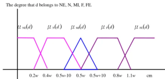
Figure 11. Membership functions of five fuzzy terms, NE, N, MI, F, and FE, where d is the distance obtained by ultrasonic sensor No. 0 or 7, and w the distance between walls.
Each of the fuzzy terms of the input variable DIR is obtained from manipulations of several fuzzy sets. These fuzzy sets can be separated into three groups. The first two are the estimated angles from ultrasonic signals on the left- and right-hand sides of the vehicle, respectively. The third is the accumulated angle from the system. The distances
obtained from two parallel ultrasonic sensors are used in this study to compute an estimated relative angle θL or θR between the vehicle and a wall on its
left- or right-hand side. Assume that the distance between ultrasonic sensors Nos. 0 and 15 is DUS as shown in Fig. 12. According to DUS and the distances detected by ultrasonic sensors Nos. 0 and 15, a deviation value VEL from the vehicle’s
direction can be computed accordingly. Similarly, another deviation value VER may be computed by
use of the data obtained from ultrasonic sensors Nos. 7 and 8. The details are described by the following equations:
tanθL = (V0,i − V15,i) / DUS;
tanθR = (V8,i − V7,i) / DUS;
(2)
VEL = (V0,i − V15,i) = tanθL × DUS;
VER = (V8,i − V7,i) = tanθR × DUS,
where Vm,i is the value detected from ultrasonic
sensor No. m at position i.
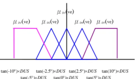
Five fuzzy sets are used to decide whether the estimated relative angle, VEL or VER, is very
left(D1), left(D2), straight(D3), right(D4), or very right(D5). The membership functions designed for
them are shown in Fig. 13. However, if the vehicle goes across an edge of a door, the estimated relative angle between the wall and itself may be very large because of the depth of the door. In other words, if an environment changes suddenly, the vehicle may not obtain a correct estimated relative angle between the wall and itself. Therefore, two fuzzy sets, CRL and CRR, are used to decide whether the
estimated relative angles from the ultrasonic signals on the left- or right-hand side of it is credible or not respectively. The two fuzzy sets are both obtained from the five fuzzy sets respectively. The main idea for designing these fuzzy sets can be categorized into three situations. The first is to decide whether the distance detected from ultrasonic sensors Nos. 0, 7, 8, or 15 is too large or not. If the answer is yes, then the estimated relative angle is not credible, because the vehicle cannot detect any wall in this case. The second situation is comparing the values of the ultrasonic signals obtained at the current node with those obtained at the previous node. If the differences between these two kinds of values are not small, then the estimated angle is decided to be incredible, because the environment may change suddenly. The third situation is comparing the
The degree that d belongs to NE, N, MI, F, FE.
μNE(d) 0.2w 0.4w 0.5w cm μN(d-) 0.5w-10 0.5w+10 0.8w μMI(d) μF(d) μFE(d) 1.1w
values from two parallel ultrasonic sensors
obtained at the current node. If the difference between the values from the two parallel ultrasonic sensors is not small, the estimated relative angle is decided to be incredible, because the environment may change suddenly, too. The membership functions designed for the above five fuzzy sets can be separated into two groups as shown in Fig. 14. The membership function shown in Fig. 14(a) is proposed for the second and third situations, and that shown in Fig. 14(b) is for the first situation.
In addition, if the vehicle is in a wide corridor, it may turn to the same direction many times so that the estimated relative direction is not correct. The accumulated angle from the system’s commands is another feature to deal with such a situation. Five fuzzy sets are used to decide whether the accumulated angle is from very left(AC1) to very
right(AC5). The membership functions designed
for these five fuzzy sets are shown in Fig. 15(a). However, the accumulated angle may not always be correct because of mechanical errors. So, a fuzzy set CRA is proposed further to decide whether it is
credible or not. The membership function proposed for CRA is shown in Fig. 15(b).
No. 0
No. 15
DUS
Figure 12. Illustration of DUS, the distance between ultrasonic sensors Nos. 0 and 15.
Figure 13. Membership functions of estimated relative angle, VEL or VER.
VL (very left) is one fuzzy term of the input
variable DIR (the deviation from the vehicle’s direction). The main steps used to obtain the degree of an input value which belongs to VL from the above-mentioned fuzzy sets are shown in Algorithm 1. The other terms of DIR are denoted in
a similar way except the fuzzy term UB (unbelievable). The main idea in defining the fuzzy term UB is that if an input value satisfies the constraint that the estimated relative angle is not credible and the accumulated angle is not credible, then the degree for this input value to belong to UB is taken to be large.
Figure 14. Membership functions of credibility CRL or
CRR.
Algorithm 1. Obtaining the degree of an input
value belonging to the value VL (very left).
Input: the value of input variable DIR (deviation
from the vehicle’s direction), including the detected values of ultrasonic sensors Nos. 0, 7, 8, 15, and the accumulated angle from system’s commands issued before; fuzzy sets, FL, FR, and FA, preselected to decide whether the estimated relative angles or accumulated angle is very left or not; the three fuzzy sets, CRL, CRR, and CRA, preselected to
decide whether the above-mentioned three kinds of detected values are credible or not, respectively.
Output: Degree of the input value belonging to VL.
Step 1. Decide whether the values from ultrasonic sensors Nos. 0, 7, 8 and 15 are credible or not by using the fuzzy sets CRL and CRR
Step 2. Combine the above-mentioned six fuzzy sets to be the fuzzy set VL according to one of the following rules.
2.1 If the ultrasonic signals on the left-hand side of the vehicle are credible, set VL as VL = CRL⋅FL + CRA⋅FA.
2.2 If the ultrasonic signals on the right-hand side of the vehicle are credible, set VL as VL = CRR⋅FR + CRA⋅FA.
2.3 If the ultrasonic signals on both sides of the vehicle are credible, set VL as VL = (CRR⋅FR + CRL⋅FL) + CRA⋅FA.
2.4 If the ultrasonic signals on both sides of the vehicle are credible, set VL = CRA⋅FA.
Step 3. Use the input value of the input variable
DIR into VL and output the degree of the
input value which belongs to VL.
μD1(ve) tan(-10°)×DUS μD2(ve) μD3(ve) μD4(ve) μD5(ve) tan(-5°)×DUS tan(-2.5°)×DUS tan(0°)×DUS tan(2.5°)×DUS tan(5°)×DUS tan(10°)×DUS 4 6 cm 480 500 cm AND (a) (b) = CRL or CRR
The output variable of the fuzzy controller for
controlling the vehicle’s direction is denoted as
ANGLE, which represents the angle and direction
used to adjust the vehicle’s direction. Eight fuzzy terms are denoted for ANGLE. The first seven fuzzy terms are defined to be from negative large to positive large. The negative large means that the vehicle turns a large angle to the left. The membership functions proposed for the seven fuzzy terms of ANGLE are illustrated in Fig. 16. The last fuzzy term means that the vehicle should stop.
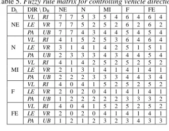
Accordingly, a total of 150 fuzzy rules are designed for ANGLE, which may be represented as a fuzzy rule matrix as shown in Table 5, and the terms of the output variable ANGLE are represented as eight numbers as shown in Table 6.
VI. EXPERIMENTAL RESULTS
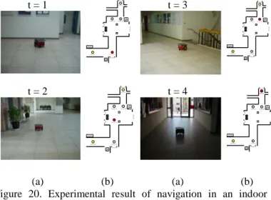
We show some experimental results of applying the proposed person following, learning, navigation techniques for the tested autonomous vehicle system in a corridors environment. The vehicle utilizes the distance between a person and itself to follow the person and learns the path data in the mean time, as shown in Fig. 17. Then it analyzes the person’s behaviors and obtains the person’s commands. If the command is TURN, then it turns left or right accordingly, as shown in Fig. 18. A map resulting from the learning session is shown in Fig. 19. And an illustration of the corresponding navigation process is shown in Fig. 20(b). Some experimental results of navigation on the path shown in Fig. 20(b) are shown in Fig. 20(a).
(a) The membership function of CRA.
(b) The membership functions of fuzzy sets, AC1, AC2, AC3, AC4, and AC5.
Figure 15. Membership functions of some fuzzy sets.
Figure 16 Membership functions of seven fuzzy terms of the output variable ANGLE.
Table 5. Fuzzy rule matrix for controlling vehicle direction.
DL DIR \ DR NE N MI F FE NE VL RI 7 7 5 3 5 4 6 4 6 4 LE VR 7 7 5 2 5 2 6 2 6 2 PA UB 7 7 4 3 4 4 5 4 5 4 N VL RI 4 1 5 2 5 3 6 4 6 4 LE VR 3 1 4 1 4 2 5 1 5 1 PA UB 2 3 3 3 4 3 4 4 5 4 MI VL RI 4 1 4 2 5 2 5 2 5 2 LE VR 2 1 3 1 4 1 4 1 4 1 PA UB 2 2 2 3 3 3 4 4 3 4 F VL RI 4 0 4 1 5 2 5 2 5 2 LE VR 2 0 2 0 4 1 4 1 4 1 PA UB 1 2 2 2 2 2 3 3 3 2 FE VL RI 4 0 4 1 5 2 5 2 5 2 LE VR 2 0 2 0 4 1 4 1 4 1 PA UB 1 2 1 2 3 2 3 4 3 3
Table 6. Fuzzy terms of output variable.
ANGLE
Left-hand rotation--- straight --- Right-hand rotation Stop
0 1 2 3 4 5 6 7
VII. CONCLUSIONS
Relevant techniques have been proposed and integrated for use on an autonomous vehicle for learning and navigation in corridor environments. The system includes four kinds of capabilities: following a person, learning paths, analyzing learned paths, and navigating on learned paths. A method of person following has been proposed, which uses ultrasonic sensors to detect the distance between a person and the vehicle. Two fuzzy controllers have been proposed to control the vehicle’s direction and speed during person following. A method for vehicle turning has also been proposed. The vehicle can analyze some of the person’s behaviors by a voting technique. When it follows the person, it learns the path data in the mean time. Then a method for path analysis has been proposed. The main feature used for navigation is path data. When the vehicle navigates on the learned path, it should know when to turn. A technique has been proposed to analyze the time for
μAC1(a)
μAC3(a)
μAC4(a) μAC5(a) μAC2(a)
a : the accumulated angle.
μCRA(a)
a : the accumulated angle.
μ0(θ) μ1(θ) μ2(θ) μ3(θ) μ4(θ) μ5(θ) μ6(θ) 0 1
The degree thatθbelongs to the fuzzy
vehicle turning. The environmental feature used to
correct the vehicle’s direction is wall.
In addition, a method for navigation has been proposed. For the vehicle to navigate along the learned path, a fuzzy controller which uses ultrasonic signals obtained during navigation and wall distances obtained from path analysis to control the vehicle’s direction has been proposed. The system can act as a tour guide in corridors environments. The experimental results show the feasibility and practicality of the proposed system.
AKNOWLEDGEMENTS
This work was supported financially by the Ministry of Economic Affairs under Project No. MOEA 97-EC-17-A-02-S1-032 in Technology Development Program for Academia.
REFERENCES
[1] Y. T. Wang and W. H. Tsai, “Indoor security patrolling with intruding person detection and following capabilities by vision-based autonomous vehicle navigation,” Proc. of 2006 Int’l Computer
Symp. (ICS 2006), Taipei, Taiwan, Dec. 2006.
[2] S. Y. Tsai and W. H. Tsai, “A Study on Mobile Robot Navigation with Simple Learning Procedures by Ultrasonic Sensing and Computer
Vision Techniques,” Proc. 2008 Int’l Computer
Symp. (ICS 2008), Taipei, Taiwan, Nov. 2008.
[3] C. H. Ku and W. H. Tsai, “Smooth autonomous land vehicle navigation in indoor environments by person following using sequential pattern recognition,” Journal of Robotic Systems, Vol. 16, No. 5, pp. 249-262, 1999.
[4] V. M. Peri and D. Simon, “Fuzzy Logic Control
for an Autonomous Robot,” Proc. 2005 Annual
Meeting of North American Fuzzy Information
Society, June 2005, pp. 337-342.
[5] J. Xin, S. Li, Q. Liao, and R. Zhan, “The Application of Fuzzy Logic in Exploration Vehicle,” Proc. 2007 IEEE Int’l Conf. on Fuzzy Systems and Knowledge Discovery, Haikou, Hainan, China, Aug. 2007, pp. 199 - 203.
[6] S. Datta, D. Banerji, and R. Mukherjee, “Mobile Robot Localization with Map Building and Obstacle Avoidance for Indoor Navigation,” Proc. 2006 IEEE Int’l Conf. on Industrial Technology, Dec. 2006, pp. 2535-2540.
[7] M. S. Islam, M. A. Azim, M. S. Jahan, and M. Othman, “Design and Synthesis of Mobile Robot Controller using Fuzzy,” Proc. 2006 IEEE Int’l Conf. on Semiconductor Electronics, Kuala
Lumpur, Malaysia, Oct. 2006, pp. 825-829.
(a) (b) (c)
Figure 17. Experiment result of person following. (a) Vehicle follows the person. (b) Vehicle’s direction has deviation. (c) Vehicle adjusts its direction to keep following the person.
(a) (b) (c)
Figure 18. Experiment result of turning. (a) Vehicle analyzes the person’s command. (b) Vehicle turns according to the command TURN. (c) The vehicle restarts to follow the person.
Figure 19. Experiment result of a learned path. Red lines are distances obtained from ultrasonic sensors.
t = 1
Starting node CV LAB
South Gate Turning nodeTurning node
Finishing node North Gate East Gate Pillar Pillar Gate Gate Current position t = 3 Starting node CV LAB South Gate Finishing node North Gate East Gate Pillar Pillar Gate Gate Turning node Turning nodeCurrent position
t = 2
Starting node CV LAB
South Gate Turning nodeTurning node
Finishing node North Gate East Gate Pillar Pillar Gate Gate Current position Turning node t = 4 Starting node CV LAB South Gate Turning node Finishing node North Gate East Gate Pillar Pillar Gate Gate Turning node Turning node Current position (a) (b) (a) (b)
Figure 20. Experimental result of navigation in an indoor environment. (a) The vehicle navigates on the path. (b) The navigation map with red circle indicating the current position.