Pergamon
ht. 1. Mach
0890-6955(95)00050-x
Tools Manufact. Vol. 36. No. 3, DD. 339-353, 1996 Copyright @ 1995 Elk&r Science Ltd Printed in Great Britain. All rights reserved 089C-6955/%S15.00 t .oO
MONITORI:NG AND SELF-LEARNING FUZZY CONTROL FOR WIRE RUPTURE PREVENTION IN WIRE ELECTRICAL
DISCHARGE MACHINING
M. T. YANt and Y. S. LIAOt$ (Received 4 January 1994; in final form 12 April 1995)
Abstract-Wire breaking is a serious problem in the application of wire electrical discharge machining (WEDM). A WEDM sparking frequency monitoring and control system based on the characteristics of the voltage waveform of WEDM is developed. A new self-learning fuzzy controller is proposed to control the sparking frequency at a safe level by regulating the pulse off-time in real time for avoiding wire rupture and maintaining a state of high metal removal rate. The developed control strategy is tested under the conditions of cutting a workpiece with continuous sharp angles, a change in workpiece height during machining process, and machining with a high feed-rate. Experimental results show that this monitoring and control system can control the sparking frequency at a predetermined level without the risk of wire rupture.
1. INTRODUCTION
Since the commercial introduction of wire-cut electrical discharge machining (WEDM) in the 197Os, technology for machining speed and surface finish has grown rapidly. However, many problems, such as machining inaccuracy resulting from the flexibility of wire, wire-breaking problems, machining parts with complex shape and electromagnetic interference (EMI), etc. are far from satisfactorily solved. Among them, wire breaking during the machining process is a serious problem in the application of WEDM. Wire rupture in the WEDM process not only greatly increases machining time, it also decreases the machining accuracy and reduces the quality of the machined surface.
Tanimura and Heuvelman [l] pointed out that the number of short sparks rose abruptly before wire rupture, and that the violent change of short-circuit pulses lasted for more than 30 msec until the wire broke. Based on these results, they developed a short circuit detecting system to avoid short sparks by adjusting the choke inductance of the pulse generator. The method is not suitable for a transistor-controlled power supply circuit which is used at the present, since no choke inductance is used. Kinoshita et al. [2] observed that a sudden rise in pulse frequency lasted for approximately 5-40 msec before wire rupture. They developed a control system to prevent the wire electrode from breaking by means of monitoring the pulse frequency. But the control strategy had a negative effect on the machining efficiency as a result of turning off the pulse generator intermittently.
Shoda et al. [3] developed an on-line monitoring system to detect the sparks’ location by comparing the measured currents which are supplied to the electrode wire through the upper and Ilower feeding points from the pulse generator. Based on the technique of the on-line spark locations, an adaptive control system has been developed to reduce the wire rupture. However, the control system only focuses on the reduction of the wire breaking ,without regard to metal removal rate because the discharge energy is decreased when the concentration of discharges at a certain point is detected. The wire breakage can be avoided by this control system but the machining speed is decreased.
Rajurkar and Wang [4, 51 developed an on-line WEDM adaptive control system
TDepartment of Mechanical Engineering, National Taiwan University, 1, Sec. 4, Roosevelt Road, Taipei, Taiwan 10764, Republic of China.
$Author to whom correspondence should be addressed. 339
340 M . T . Yan and Y. S. Liao
that monitors and controls the sparking frequency at optimal levels according to the on-line identified workpiece height. Experimental results show that the proposed control system can successfully control the sparking frequency at the optimal value without the risk of wire rupture when cutting a workpiece with variable heights. In this control system, application of adaptive strategy to sparking frequency control of the WEDM process requires a well-defined mathematical model (a linear deterministic discrete model). However, the metal removal process of WEDM involves complicated and time-varying characteristics. Moreover, the process features change drastically with the machining parameters such as servo feed, pulse on time, flushing pressure, etc. Thus, accurate modeling of the metal removal process is difficult if not impossible. Accord- ingly, the complex dynamics of the WEDM system makes the conventional control scheme [2] and adaptive control [4, 5] inapplicable to the wide range variations of machining conditions in WEDM.
Fuzzy control theory can easily capture the approximate and qualitative aspects of human knowledge, and perform reasoning. The control strategy has been proved to be very successful in dealing with various industrial processes where mathematical models are unknown or ill-defined [6]. However, it is difficult for a control strategy with linguistic description to represent perfectly the operator's experience and expert's knowledge. Moreover, some significant changes in industrial process may be outside the operator's experience. Hence, it is difficult to design the linguistic control rules of a general fuzzy controller so as to achieve good control performance. In order to overcome this difficulty, designing a fuzzy controller with learning capability is essential. For the WEDM process, it is well known that a high metal removal rate is closely related to a high value of pulse frequency. But, the high sparking frequency will increase the possibility of wire rupture due to the high power density. In this paper a WEDM sparking frequency monitoring system is developed, and a self-learning fuzzy control strategy is proposed not only to control the sparking frequency at a safe level, but also to maintain a high metal rate by on-line adjusting of the pulse off-time under a constant feed-rate machining condition.
2. E X P E R I M E N T A L EQUIPMENT AND WEDM SPARKING FREQUENCY MONITORING SYSTEM
2.1. Experimental equipment
A prototype WEDM machine, developed by the Mechanical Industrial Research Laboratory (MIRL) of ITRI, Taiwan, is employed. This machine consists of an iso° energy power supply system, a dielectric regeneration system, a computer numerical control system, a five-axis motion system and a flushing device. The discharge power supply system of this machine is shown in Fig. 1. The system consists of a low power circuit and a high power circuit. The low power circuit leads the gap to discharge by supplying a low voltage of 110 V, while the high power circuit contributes to the metal removal by supplying 220 V. Switching of these two circuits is controlled by a control board. The discharge current has a triangular waveform with a constant slope of 380 A/ izsec. Flushing pressure can be controlled by a hand valve. Copper wire (cathode) and tool steel (anode) are used for the electrode and the workpiece, respectively. The wire diameter is 0.25 mm. The adjustable parameters of this machine are listed in Table 1. These parameters include pulse on-time, pulse off-time, servo reference voltage, servo feed speed, wire speed and wire tension. The following experiments are conducted under constant feed rate condition, hence, the servo reference voltage is not used. The feed-rate can be set by a human operator according to the operating table offered by the machine tool builder. The pulse on-time for an iso-energy pulse generator is fixed, thus the sparking frequency is mainly determined by the pulse off-time. The maximum stable machining speed for this machine is about 120 mm2/min.
Wire Rupture Prevention in WEDM 341 High power - (220V) gap ÷ Low power 1 (I t0V)
T J
I
I
Control board ]I/O [ [ on/off line
~ n a b l e signal
Fig. 1. WEDM power supply circuit.
Table 1. Adjustable parameters of ITRI's WEDM machine
Items Range
Pulse on-time 0.1-0.3 gsec (30 steps)
Pulse off-time 1.6-4.8 p.sec (30 steps)
Servo reference voltage 10-70 V
Feed rate override 0-255%
Wire feed 0-20 m/min
Wire tension 10-2500 gf
2.2. WEDM sparking frequency monitoring system
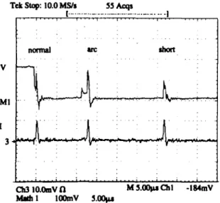
In order to prevent the wire from breaking and to improve the machining efficiency, monitoring and analysis of gap conditions is needed. Gap conditions can be identified from the voltage and the current waveform. Figure 2 shows the typical gap voltages
T~ Stop: 10.0 ld..~s 55 Acqs [ . . . I ~ , i . . . . z , T . . . . i , i ... , ... r , , normal arc ~ x t i . . . i. • ' i i MI Oh3 tO.OmVfl MS.00~Cht -tS4mV t 100mY 5.00~
Fig. 2. Typical gap voltage and current waveforms of a W E D M process. (50 V/div for gap voltage, I00 A/
342 M . T . Yan and Y. S. Liao
(top plot) and their associated current waveforms (bottom plot). In this figure, there are three sparks. The first one is a normal spark. The gap voltage begins at 80 V, followed by the discharge of the gap at a lower voltage with a high discharge current. After a short period of time (11.2 issec), the other spark (arc spark) begins. The third one is a short spark. By analyzing the pulse trains, the following characteristics are found. (1) The ignition delay time of a normal spark is apparently longer than that of the abnormal spark. The ignition delay voltage of a normal spark (above 80 V) is higher than that of the abnormal spark (below 20 V). (2) The sparking frequency of WEDM ranges from 10 to 60 kHz.
Based on the above features, a WEDM sparking frequency monitoring system has been developed. The voltage signal is sensed by the gap-detecting circuit, made up of a precircuit and a compartor circuit. The discrimination between normal sparks and arc sparks can be made through a logic decision circuit according to the duration of the ignition delay. After logic analysis, the pulses are classified into two types, namely normal and arc discharge pulses, respectively. Due to the large interference of noises and the difficulty in differentiating the voltage level between arc and short sparks, the short sparks are categorized in the arc pulse group. With this kind of classification, the total sparks are composed of normal sparks and arc sparks. These pulses are converted to transistor-transistor logic (q'q~L) signals by a photocouple circuit to reduce the interference of high-frequency noise. The number of sparks in a selected sampling period is counted by using an AX5216 counter card, and the number of sparks per unit time (defined as sparking frequency) is computed and stored. The sampling period can be set in the range of 2-65535 msec.
3. A SELF-LEARNING FUZZY CONTROLLER
A rise of the sparking frequency leading to wire breakage has been identified by many researchers [1-5, 7]. Therefore, the sparking frequency should be controlled at a constant level in order that wire breaking can be prevented. In addition, it should be noted that the machining speed (metal removal rate) is related to total sparking frequency. Hence, the target of control should maintain a high metal removal rate while avoiding wire breakage. It was mentioned before that the sparking process of WEDM is a complex and time-varying system, and a new self-learning fuzzy controller (SLFC) is proposed for this purpose. Some experimental results [2, 3, 6] have demon- strated that the duration of the wire rupture symptom can last for about 50 msec. It is difficult for a control system to respond rapidly enough for such a short duration by adjusting the feed rate parameter. Bandwidth of the spark generation system (in an order of kHz) is much higher than that of the servo mechanism (less than 50 Hz). Hence, in the proposed control strategy, the pulse off-time rather than the feed rate is on-line regulated to keep the sparking frequency under a critical level to prevent the wire from breaking. The SLFC consists of a fuzzy controller, generalized delta rules and a fuzzy performance measure. The fuzzy controller is composed of a fuzz- ification interface, a knowledge base, decision-making logic and a defuzzification inter- face [8]. The generalized delta rule [9] provides the SLFC's learning ability by adjusting the weighting factors of the fuzzy rules. The function of the fuzzy performance measure, employing fuzzy logic, provides a quantity for the learning rule modification. As a result, the weighting factors of the fuzzy rules can be updated. Figure 3 illustrates the signal flow of the proposed controller, and detailed functions of each part are described as follows. Since the objective is to keep the sparking frequency at a constant level, the sparking frequency error is adopted as the major variable of the controller input. In addition, the change of the sparking frequency error, which reflects the dynamics of the machining process, is adopted as another input variable. The linguistic variables to be used in the premise of control rules are defined as:
e: = sparking frequency error
Wire Rupture Prevention in WEDM 343 :~ce • = • • ~ i e NB NS Z PS PB
P:looooo
o o o o o I I ~ . J I , ~ Defuz.zifier ' o o o o O l i ~ 1 . , I unttNSlOOOOO
NB 0 0 0 0 0l
p¢ Yr performance ) m e a s u r e Y ~ WEDMI
system u(t-1)Fig. 3. The signal flow of the self-learning fuzzy controller.
ce: = change of sparking frequency error
= (current sparking frequency error-previous sparking frequency error) x GCE where GE and (ICE are scaling factors and their values are GE = 0.5 and GCE = 0.1, respectively.
Five linguistic sets on the domains of definition are specified: NB, NS, ZO, PS and PB, where P, B, S, N and ZO correspond respectively to positive, big, small, negative and zero. Figures 4(a) and (b) illustrate the membership function of the linguistic values of input of the controller (i.e. e and ce) and the output of the controller. In these two figures, an isosceles-triangle-shaped function is chosen as the membership function of each linguistic set because of its convenient manipulation. Based on the
(a) NB NS ZO PS PB -2 -I 0 I 2 e o r c e (b) NB NS ZO PS PB -2 -t o I 2
uf
344 M. T. Yah and Y. S. Liao
Table 2. Rule base for the fuzzy logic controller
I e/ce PB PS Z O NS NB PB I PS [ZO INS I NB I PB PS PS PS NS NS NS NB Ps
ii
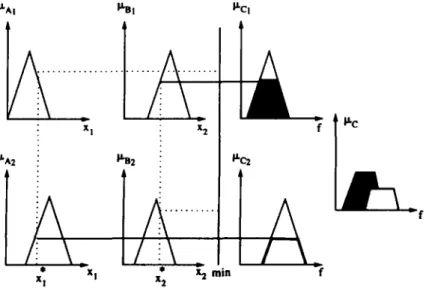
PS NS ZO NS NB NB NB NS NS NB NB NBauthors' experience in WEDM, 25 control rules are formulated as shown in Table 2. The max-min inference method [10] is used to perform the fuzzy reasoning on the linguistic control rules. The fuzzy reasoning process is illustrated in Fig. 5. For simplicity, assuming that we have two fuzzy control rules:
R U L E 1 : IF xl is A l and x: is B1 T H E N f is C1 R U L E 2 : IF x~ is A2 and x2 is B2 T H E N f is C2.
If x; and x2 are the sensor readings for fuzzy variables x~ and x2, and if p,,4~ and I~n~ are the membership function for A and B, respectively, then the grade of member- ship of x; in A~, and the grade of membership of x2 in B are represented by I~At(X;) and ~n~(x~), respectively for rule 1. Similarly for rule 2, p, A2(X;) and i~a2(x2) are used for the grades of membership.
The firing strengths of the first and second rules are calculated by
et] = min(ixA](x;), p, al(x~)) (la)
or2 = min(l~A2(x]), ~a2(x2)). (lb)
In this method of reasoning, the jth rule recommends a control decision as follows:
~ c ~ = min(%-, ~tcj(f)), (2)
where ~ is the fuzzy set representing the recommended control action of the jth rule, and C i is the consequence of rule j. The variable f is a point on the linguistic scale of
x I x 2 f
P'n2 tiC2
1
* X I *
xl x2 x 2 rain f
Fig. 5. Graphic representations of the max-rain inference method.
Wire Rupture Prevention in WEDM 345
control action C_ The function P,c; is the final output membership function of rule j.
Accordingly, the membership function of the combined control action C is given by
Ixc(f) = max(Ixc;(f), P.c2(f)) •
(3)
The centre of area method is employed for the defuzzifier unit, and the method can be represented by
A(,,j)
x x w, u / = ~-_t ~ A(%)/=1
(4)
where u r is the output of the controller, and fj typically represents the centroid of a membership function or a singleton defining the jth rule output variable. The variable A(%) represents the firing area of the jth rule, and n is the total numbers of the firing rules. The weighting factor wj provides a measure of the importance of the jth rule, and it eventually can learn from the system performance. The w~ are initialized to be all equal because it is assumed that each rule is equally important. The weighting factor of each rule is modified according to the generalized delta rule given by
w j ( k ) = w j ( k - 1) + c x aj x 8.
(5)
The 8 is a quantity of rule modification calculated by the fuzzy performance measure (FPM), coefficient c is a learning constant and k is an index of time increment. The
function of the FPM can be considered as a non-linear mapping from e ( k ) (i.e. error
at kth sampling instant) and e ( k - 1) to 8, and it can be represented as
8 = F ( e ( k - - 1 ) , e ( k ) ) . (6)
The FPM's structure is similar to that of a fuzzy rule-base strategy. Hence, the quantity 8 can be calculated similar to uf. The linguistic variables to be used in the conditions of the fuzzy rules are defined as
pe: = e( k - 1) x GPE
e: = e ( k ) x G E ,
where GPE and GE are scaling factors and their values are GPE = 0.5 and GE = 0.5, respectively.
The linguistic fuzzy variables for fuzzification of the FPM's input terms ( p e and e)
and output terms are defined in the variable universe of discourse in the order of negative big (NB), negative small (NS), zero (ZO), positive small (PS) and positive big (PB). These five fuzzy linguistic variables are quantized as the following five fuzzy subsets: NB [-~c, - 2 ] , NS [ - 2 , 0], ZO [ - 1 , 1], PS [0, 2], PB [2, ~]. In this FPM's fuzzy rule strategy, an isosceles-triangle-shaped function is also chosen to the membership function of each linguistic set. In essence, the FPM's inference rule is designed according to the following concepts: if the system performance improves, the quantity 8 should reward the rules that fired by increasing the weighting factors associated with higher or). On the other hand, if the system performance deteriorates, those rules that fired should be punished by decreasing the weighting factors. Besides, the control force should be reduced by decreasing the weighting factors associated with higher ct) as the output state approaches the set point. Based on these concepts, the
346 M . T . Yan and Y. S. Liao
fuzzy rules of FPM are formulated and given in Table 3. The mean of maximum method is employed for the defuzzifier unit, and the quantity 5 can be calculated by
/
__]=I
l (7)
where 8j represents the centroid of a membership function of the jth rule output variable, and l is the total number of firing rule.
The real control force applied to the plant is calculated by
u ( k ) = u ( k - 1) + uAk),
(8)
where u(k) is the control signal at the kth sampling instance, and it is defined as the reciprocal of pulse off-time (to), i.e. to = 1/u.
4. EXPERIMENTAL RESULTS
An IBM PC/AT-286 is used externally for control purposes, and the control law is written in C language. The RS485 interface card is used to handle the input/output (I/O) data and to communicate with the industrial personal computer (IPC) of the machine. The sparking frequency has a constant level with a small amount of high- frequency variation because of the stochastic nature of the discharge process. In order to obtain the constant level for control purpose, a digital Butterworth low pass filter is used to filter the high-frequency variation. The sampling frequency used in our experiments is 50 Hz. Hence, one-tenth of the Nyquist frequency (half the sampling frequency), i.e. 2.5 Hz, is selected as the cut-off frequency of the low pass filter. The pulse off-time computed from the SLFC is updated through the RS485 card to the IPC of the machine. In order to verify the applicability of the proposed SLFC, some experiments are conducted under conditions where wire rupture is prone to occur statistically. These conditions include machining of a workpiece with continuous sharp angles, a change in workpiece height during machining process, and the high feed-rate machining condition.
4.1. Machining of a workpiece with continuous sharp angles
Figure 6(a) shows the wire rupture process when a S K D l l workpiece with a height of 50 mm is machined. Figures 6(b) and 6(c) show the test results under the same machining condition but with the proposed fuzzy controller. Machining and controller parameters are the test 1 given in Table 4. In the table, w0 is the initial weighting factor and Yr is the predetermined reference frequency. Figure 6(b) indicates that the sparking frequency is kept at a level of 11.8 kHz until the control action starts at the time instant of 60 sec. The sparking is rapidly controlled to the reference value through the adjustment of pulse off-time. As can be seen from Fig. 6(c), the pulse off-time is increased accordingly as the control action starts in order to keep the sparking frequency at a constant level. It is noted that due to the discontinuity of the pulse off-time and high initial value of the weighting factor, there exists an overshoot before the sparking
Table 3. Rule base for fuzzy performance measure
[
e/pe laB [PS [ZO INS I NBI
PB PS ZO NS NB
Ps
NB
INB
PB NS NS NS PS NS ZO NS PS NS NS NS PS PB NB NBWire Rupture Prevention in WEDM 347 ( a ) 2 4 16- =o i
I
l I I i i I i i I I I 30 60 90 120 Time (sec) (b) 24 ,-r' 16Control action starts
\
i I I I i i i i i i i i i i I I I 5 0 I 0 0 1 5 0 Time (sec) (c) 4 0 , 32-- 24 ~ ..~ © 8 -Control action starts
I I I f I I | i i i i i ~ , i i l
.50 I 0 0 1 5 0 2 0 0
Time (see)
Fig. 6. (a) A wire rupture process without control action, (b) the sparking frequency and (c) the pulse off- time with the fuzzy controller during the machining of a workpiece having continuous sharp angles.
Table 4. Machining parameters and controller parameters used in the experiments
Machining parameters Controller parameters
flushing
Test on-time feedrate wire speed wire tension pressure c wo Y,
No. (nsec) (mm/min) (m/min) (gf) (bar) x 10 -7 x 10 -3 (kHz)
1 600 0.5 5 1,000 2 2 5 11
2 500 1 6 1,000 2 2.5 8 26
3 900 1.8 6 1,200 2 2.5 8 25
348 M . T . Yan and Y. S. Liao
frequency reaches the desired state as depicted in Figs 6(b) and (c). Without this monitoring and control system, the sparking frequency could gradually increase and cause wire breakage as shown in Fig. 6(a). This experiment proves that wire breakage can be avoided while maintaining the process in a high metal removal state by employing the developed system.
4.2.
A change of workpiece height during machining process
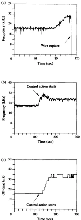
Figure 7(a) shows the variation of the sparking frequency before wire rupture during cutting a variable height SKDll workpiece. As we can see from this figure, the sparking frequency gradually rises from 21 kHz to the level of 30 kHz as the cutting height is changed from 35 mm to 50 mm. The duration of the high sparking frequency symptom
(a) 24
32~ 24
16
g 8d
/ ¢
Wire rupture Time (scc) 120 (b) 4o 32- = 1 6 - - 8 -Control action starts
I ~ 1 I I I I r r I I I l I
0
100
200
300
Tinm (sec) (c) 5o 40 3O • 20 I0 ¸/
Control action starts
I I I t i I d I ~ ' I I
100 200 3OO
Time (sc¢)
Fig. 7. (a) A wire rupture process without control action, (b) the sparking frequency and (c) the pulse off- time with the fuzzy controller when a workpiece with a change in cutting height is machined.
Wire Rupture Prevention in WEDM 349 lasts for 15 sec before wire rupture. Figures 7(b) and (c) show the time history of the sparking frequency and the pulse off-time, respectively, with this fuzzy control system under the same machining condition as that of Fig. 7(a). Machining and controller parameters are given in Table 4 as well (test 2). As shown in Fig. 7(b), the sparking frequency is maintained at a constant level of 21 kHz before control action starts. The sparking frequency varies as a result of changing the cutting height. Once the sparking frequency rises to more than the constant level by a specific value (2 kHz), the control action starts and thus, the sparking frequency is controlled to a predetermined level of 26 kHz. Figure 7(c) shows the pulse off-time is promptly adjusted by the proposed control strategy when the height of workpiece is varied during machining. This exper- iment demonstrates that the sparking frequency can be controlled at a safe level without the risk of wire rupture when a workpiece with a change in cutting height is machined.
4.3. High feed rate machining condition
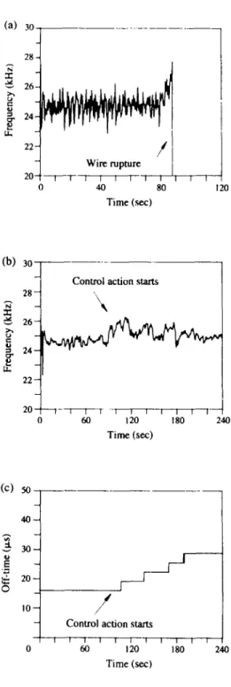
Figure 8(a) shows the wire rupture process when a SKDll workpiece with a height of 50 mm is machined under a high feed rate condition. Machining speed under such condition is about 90 mm2/min. As can be seen from Fig. 8(a), the sparking frequency rises to a level of 27 kHz before wire rupture. Figures 8(b) and (c) show experimental results with the fuzzy controller for the same machining condition. Machining para- meters and controller parameters are test 3 given in Table 4. Figure 8(b) demonstrates that the sparking frequency is sluggishly controlled to a reference level. As illustrated in Fig. 8(c), the pulse off-time is consecutively changed from 16 p.sec to 28.8 i~sec by the control strategy during the machining process. The sparking frequency cannot be promptly regulated through the adjustment of the pulse off-time because the perform- ance of the WEDM process is strongly influenced by the high servo feed rate. This is the reason why the pulse off-time is largely increased in order to reduce the sparking frequency to the reference level. Nevertheless, with this control system, high-speed machining can be maintained while avoiding the wire rupture.
5. DISCUSSION
Having demonstrated the experiments of a self-learning fuzzy controller for WEDM process, in this section we address several issues in applying fuzzy logic to this process. The choice of Yr is to maximize metal removal rate while keeping the wire electrode in the safe operating region. Its value can be defined by the experimental study and theoretical analysis of the thermal load on a wire electrode [5]. The research of the optimal value of Yr based on the Taguchi experimental method is under way.
Since many industrial processes are controlled by PID controllers, it is logical to compare the proposed SLFC with PID controllers. PID controllers are widely used because of easier implementation and tuning. However, WEDM process is a highly non-linear and time-varying system owing to the variations of the machining condition and coupling effect of the machining parameters. It is difficult to design a PID controller for such a complex system. A linear difference equation such as that proposed by Rajurkar and Wang [4, 5] may be used as an approximate mathematical model to design a PID controller. However, it should be noted that the model parameters rely heavily on the machining parameters. PID controllers based on the approximate mathematical model cannot be applied to a wide range of variations in machining conditions in WEDM. Unlike PID controllers based on an explicit mathematical model, the SLFC can simulate operators' experience, human intelligence and experimental information for controlling the WEDM process. The scaling factors (i.e. GE, GCE and GPE) of the SLFC can be calculated by the criterion proposed by Braae and Rutherford [11]. The initial weighting factor (Wo) and learning rate (c) of the gen- eralized delta rule can be determined from the viewpoint of convergence speed and system response [12, 13]. In general, a high value of initial weighting factor results in a fast response and a long settling time, and vice versa. If the learning rate is small,
3 5 0 M . T . Y a n a n d Y. S. L i a o 3o 28 26 24 22 -~ Wire rupture 20-j" t 7 - I i i I D I 40 Time ( s e c ) , -t-~ 80 120 (b) .r- ,5 ,-I 30 28 26 2 4 - 2 2 - 20 0 C o n t r o l a c t i o n starts \ 1 - I t T -1 ~ i -i ~ 60 1 0 1 0 Time (sec) 240 (c) 0 50 4 0 - - 3 0 - - 2 0 - - IO-- I I I I 0 180 240
f
J/
C o n t r o l a c t i o n starts r I I 1 | I 6O 102 Time (sec)Fig. 8. ( a ) A wire rupture process without control action, (b) the sparking frequency and (c) the pulse o f f -
t i m e with the fuzzy controller during high feed rate machining condition.
the speed of learning is slow, but the transition of the system dynamic behaviour is stable, and vice versa.
As depicted in Fig. 2, the discharge current is an approximate isosceles-triangle- shaped waveform and thus, the current rise time (on-time) is equivalent to the current fall time. Since the current rise is constant at 380 A/l~sec, the average current for each machining condition can be calculated as: (on-time peak) × (current sparking) x (frequency). Taking test 1 as an example, the pulse on-time, the peak current and the sparking frequency are 600 nsec, 228 A and 12 kHz, respectively. Hence, the average value is 1.65 A. For test 2, the pulse on-time, the peak current and the sparking frequency are 600 nsec, 190 A and 22 (or 28 kHz), respectively. The average is 2.1 A (or 2.7 A). Similarly, the average current is 7.7 A for test 3 as the pulse on-time, the
Wire Rupture Prevention in W E D M 351 c - O c- O e'. E [.., a == "'7 .'- :a. .=_ e.. I ¢.. • = ~ - 6 z ~ e q ~ e~, ¢-q u,q ~ ,.O i-~ ¢ q e, ~ , r-- o, ~ ~ t " ~ ~ t r 3 ~
352 M.T. Yan and Y. S. Liao
peak current and the sparking frequency are 900 nsec, 342 A and 25 kHz, respectively. Compared with the peak currents, the average currents are relatively small. However, these values are reasonable since the pulse times used in the WEDM process are quite short. Research has shown that erosion rates of the anodic workpiece are higher than those of cathodic wire electrode for short pulse times [14]. Under short pulse time conditions, a high current rise is commonly employed to achieve a higher discharge energy (or a higher current density) and thereby obtaining a high metal removal rate. For an iso-energy power supply system, the average cycle time (i.e. the reciprocal of the pulse frequency) is composed of average ignition delay time, off-time and on- time. By observation and analysis of experimental results, the average ignition delay time under initial machining condition, bad gap condition (marked with an arrow in Figs 6-8) and final machining condition for each test are shown in Table 5. As depicted in Table 5, ignition delay times are initially longer than off-times and remain so for test 1. On the other hand, ignition delay times are finally shorter than off-times for test 2 and test 3. During the bad gap condition, ignition delay times becomes decreasing and unsteady. This phenomena is similar to some experimental results [1, 7] in that total number of abnormal sparks per sampling interval suddenly rises before wire rupture. It reveals that under the bad gap conditions of three tests, the controlled off- time is increased to remove the unsteady ignition delay, and to reduce the abnormal sparks. As the process reaches a steady state (final machining condition), the sparking frequency is kept at a reference level and the ignition delay times is kept at a steady value for all tests.
It is experimentally found that the sparking frequency is also strongly influenced by the servo feed parameter. The higher the feed rate, the stronger is its influence on the sparking frequency. Thus, the sparking frequency cannot be controlled to a very large level under a high feed rate machining condition by only adjusting the pulse off- time. The servo feed parameter also greatly affects the performance of the WEDM process. The research on an adaptive servo control system based on the fuzzy logic strategy is continuing in our laboratory.
6. CONCLUSION
In this paper, a WEDM sparking frequency monitoring and control system is developed. The proposed controller employs the fuzzy logic as a rule-base control strategy and the generalized delta rule associated with fuzzy performance measure as a learning unit. The controlled off-time is increased to remove the unsteady ignition delay, and to reduce the abnormal sparks so that the pulse frequency can be kept at a reference level. It is shown that the SLFC possesses superior robustness to overcome a wide variety of machining conditions in WEDM. With this monitoring and control system, the sparking frequency is controlled in the high metal removal rate state without the risk of wire rupture under various machining conditions.
Acknowledgements--Support from National Science Council, Taiwan, is gratefully acknowledged.
REFERENCES
[1] T. Tanimura and C. J. Heuvelman, The properties of the servo gap sensor with wire spark-erosion machining, Ann. CIRP 26, 59-63 (1977).
[2] N. Kinoshita, M. Fukui and G. Gamo, Control of wire-EDM preventing electrode from breaking,
Ann. CIRP 31, 111-114 (1982).
[3] K. Shoda, Y. Kaneko, H. Nishimura, M. Kunieda and M. X. Fan, Adaptive control of WEDM with on-line detection of spark locations, lOth Int. Syrap. for Electro-Machining, (ISEM-10), pp. 410-416 (1992).
[4] K. P. Rajurkar and W. M. Wang, On-line monitor and control for wire breakage in WEDM, Ann.
CIRP 40, 219-222 (1991).
[5] K. P. Rajurkar and W. M. Wang, WEDM identification and adaptive control for variable-height components, Ann. CIRP 43, 199-202 (1994).
[6] M. Sugeno, Industrial Application of Fuzzy Control. North-Holland, Amsterdam (1985).
[7] Y. S. Liao, Y. Y. C-'hu and M. T. Yan, Study of wire breaking process and monitoring of WEDM,
Sino-German loint Syrap. on Precision and High Speed Manufacturing Technology, Taipei, Taiwan,
Wire Rupture Prevention in WEDM 353 [8] C. C. Lee, Fuzzy logic in control systems: fuzzy logic controller--Part I and Part II, IEEE Trans.
Systems, Man Cybernetics 20, 404-435 (1990).
[9] D. E. Rumelhart, G. E. Hinton and R. J. Williams, Learning in Internal Representations by Error
Propagation, In Parallel Distributed Processing: Explorations in the Microstructures of Cognition, Vol.
1, pp. 318-362 MIT Press, Cambridge (1986).
[10] M. Mizumoto, Fuzzy controls under various fuzzy reasoning method, Information Sci. 45, 129-151 (1988).
[11] M. Braae and D. A. Rutherford, Selection of parameters for a fuzzy logic controller, Fuzzy Sets and
Systems 15, 185-199 (1979).
[12] T. Fukuda, T. Shibata, M. Mitokita and T. Mitsuoka, Neuromorphic control: adaptation and learning,
IEEE Trans. Ind. Electron. 39, 497-503 (1992).
[13] J. A. Zurada, Introduction to Artificial Neural System. West Publishing Company (1992).
[14] D. D. Dibitonlo, P. T. Eubank, M. R. Patel and M. A. Barrufet, New spark model proves EDM stock removal caused by superheating, EDM Digest, July/August, pp. 6-11 (1990).