4074 IEEE TRANSACTIONS ON MAGNETICS, VOL. 44, NO. 11, NOVEMBER 2008
Sliding Mode Control Using Virtual Eigenvalue Method for Compact
Optical Image Stabilization Actuators
Hsing-Cheng Yu
1;2and T. S. Liu
1Department of Mechanical Engineering, National Chiao Tung University, Hsinchu 30010, Taiwan
Electronics and Opto-electronics Research Laboratories, Industrial Technology Research Institute, Hsinchu 31040, Taiwan
The latest research in optical image stabilization actuators (OISA) focuses on improving the image quality of high resolution cameras in a photographing optical system (POS). The focal image blur is always caused of external and environmental jitter when pictures of an image sensor are acquired by photographers. Several works concerned for OISA are emphasized mainly OISA design methods; con-sequently, they are devoted to minimizing dimensions and maximizing driving magnetic force with low power consumption. Although two proportional-integral-derivative controllers and lead-lag compensators have been proposed to position dual axes of OISA in a POS, they lack robustness to compensate nonuniform friction, system uncertainty, and external disturbance. Therefore, this work aims at the sliding mode control (SMC) using virtual eigenvalue method to achieve fast time response and accurate position despite vibration from external jitter and friction of a compact OISA. The sliding surface can be reached in finite time to match disturbance. Accordingly, the SMC algorithm works well despite system uncertainty and external disturbance, and then the time response of simulation and experi-ment are matched. In consequence, the settling time of dual axes are converged within 0.2 s when the dual axes of movable platform of a compact OISA move at 0.5 mm stroke in a POS.
Index Terms—Image stabilization, linear actuator, sliding mode control.
I. INTRODUCTION
T
HE focal image blur is usually caused to external and envi-ronmental jitter while pictures of an image sensor are ac-quired by photographers. This problem deteriorates sharply in environmental darkness at slower shutter speed, or acquired dy-namic images of cameras. Due to these problems cause by jitter, digital and optical anti-shake approaches are widely adopted to compensate camera shaking [1], [2], especially used for digital still cameras (DSC) and mobile phone cameras (MPC). Actually the mechanism of optical image stabilization actuators (OISA) is not easily assembled into a restricted space; hence, anti-shake technique of MPC still stays in digital image compensation. Moreover, the ability of digital anti-shake technique is restricted to an image sensor or calculating skill of image processor; con-sequently, mechanical OISA become more essential. Two main mechanical approaches of OISA, lens shifting and image sensor (i.e., CCD or CMOS) shifting, have been proposed to compen-sate external jitter and system disturbance [3], [4]. In addition, the methods of piezoelectric actuators and shape memory alloy have also been presented; however, they require higher power than voice coil motors type (VCM-type) module [5]. Recently, the latest research in OISA of MPC focuses on improving the image quality of high resolution cameras. The characteristics demands of OISA have fueled with low power consumption, subminiature dimension, accurate movement, and low cost [6], [7]. Thus, a compact VCM-type OISA nowadays is the best and effective solution to addressing focal image quality.Conventional controllers of OISA in a photographing optical system (POS) focus on proportional-integral-derivative and lead-lag compensators [8]; nonetheless, these compensators lack robustness to compensate nonuniform friction, system
Digital Object Identifier 10.1109/TMAG.2008.2002787
Color versions of one or more of the figures in this paper are available online at http://ieeexplore.ieee.org.
Fig. 1. Computer-aided manufacturing structure and experimental prototype of a compact optical image stabilization actuator in a photographing optical system.
uncertainty, and external disturbance. The sliding mode con-trol (SMC) law offers an effective position method in which insensitivity to parameter variations and disturbance rejection capability. Therefore, this paper develops a SMC law using virtual eigenvalue method to achieve fast time response and accurate position despite vibration from external jitter and friction of a compact OISA in a POS. The sliding surface can be reached in finite time to match disturbance effectively. In consequence, the movable platform of a compact OISA in a POS can carry an image sensor to arrive at the desired location and obtain clear images immediately.
II. MECHANISM OF OPTICAL IMAGE STABILIZATIONACTUATORS
The compact OISA mechanism is an effective apparatus to suppress external and environmental jitter and access clear im-ages of an image sensor immediately; thus, the computer-aided manufacturing structure and experimental prototype of a com-pact OISA in a POS are illustrated in Fig. 1. The comcom-pact OISA has been designed and characterized by subminiature dimen-sion, precise movement, and low power consumption [4], [7]. Table I shows the whole characteristics of the designed OISA in a POS. The mechanical structure of a compact OISA basi-cally consists of a stationary base and a movable platform for linear movement in two orthogonal directions, i.e., the first and 0018-9464/$25.00 © 2008 IEEE
YU AND LIU: SLIDING MODE CONTROL USING VIRTUAL EIGENVALUE METHOD 4075
TABLE I
CHARACTERISTICS OF ACOMPACTOPTICALIMAGESTABILIZATIONACTUATOR
second axes. They can be integrated in a subminiature dimen-sion tightly, and then they work together for accurate position control of anti-shake in a POS. An image sensor shifting ap-proach is applied in this work; accordingly, an image sensor is mounted on a movable platform of a compact OISA. A mov-able platform is equipped with an upper cover, a printed cir-cuit board (PCB), a thrust ball bearing, and a lower base. Four coils are laid out on a PCB, in which two sets of opposite coils are series connection. Four permanent magnets assembled on a stationary base generate main magnetic flux. As a result, a VCM-type OISA mainly contains two sets of coils and four permanent magnets to actuate a movable platform in two or-thogonal directions; moreover, the driving force of the present compact OISA leads to 70.86 mN/A. In addition, two Hall ef-fect sensors (AsahiKasei HW-105A) in dual axes are adopted to estimate the precise position of a movable platform in OISA to detect the magnitude of the magnetic field. The stroke range of a single direction is 0.6 mm, and it depends on the designed POS.
Besides, an equilibrium system is equipped with four balance balls inserted in a PCB and four balance magnets mounted on a stationary base to maintain an equilibrium position without actuating. Moreover, in order to reduce and restrain significant friction between a movable platform and a stationary base, a thrust ball bearing is adopted and let linear movement smoothly. Additionally, two gyro sensors characterized by low noise and high sensitivity detect pitch and yaw motion of a compact OISA in a POS, and then the motion two orthogonal directions of a compact OISA are calculated and compensated effectively. Fur-thermore, an image sensor moves in two orthogonal directions to counteract external and environmental jitter. Less than 5 mA driving current is infused into coils of a PCB, and two sets of coils can generate enough orthogonal Lorentz forces to actuate a movable platform of a compact OISA in a POS. Therefore, the
present compact OISA satisfies subminiature dimension, pre-cise movement, and low power consumption requirements to employ in a POS.
III. MATHEMATICALMODEL
Two orthogonal directions are required and designed for a compact OISA in a POS; moreover, dual axes of OISA are con-trolled, separately. The dynamic equations of the present com-pact OISA satisfy the Kirchhoff’s voltage law and Newton’s second law of motion [9]
(1) (2) where and are the driving voltage and current, respec-tively, and are the coil resistance and inductance, respec-tively, and are the speed and inertia of movable platform of OISA, respectively, is the damping constant, and are electromotive and loading forces, respectively, and are the voltage and force constants, respectively. All parameters of the compact OISA are listed in Table I.
Laplace transformation for (1) and (2) yield the single axis transfer function
(3) Additionally, the mathematical model of a compact OISA in a POS can also be obtained from system identification experi-ments. Angular motions of a MPC detected from two gyro sen-sors are small, so they can actually be regarded as tiny linear movement. Additionally, two orthogonal directions of a com-pact OISA can be actuated and controlled independently. The testing frequencies of the signal analyzer vary from 5 to 1000 Hz for dual axes, respectively. Laser beam, projected upon a single axis of a compact OISA, is controlled by using a vibrom-eter. Infuse various voltages into a compact OISA, and velocity variation outputs can be measured from a vibrometer. Conse-quently, the frequency responses in system identification exper-iments are obtained by adoption an analyzer. As a result, their identified transfer functions of dual axes are respectively formu-lated as
(4) (5)
IV. DESIGN OFSLIDINGMODELCONTROLLER BYUSING VIRTUALEIGENVALUEMETHOD
Despite use transfer functions of OISA plant deduce from dynamic equations or system identification; the model (3), (4) or (5) can be rewritten in state-variables form as
4076 IEEE TRANSACTIONS ON MAGNETICS, VOL. 44, NO. 11, NOVEMBER 2008
where the system state vector , is the control
input, is the displacement of the movable platform
of OISA, and the disturbance vector caused by
system uncertainty and external disturbance is bounded within
a known boundary function .
The virtual eigenvalue method [10] is one of the design method of sliding mode controller adopted in this work to design an appropriate sliding vector of a sliding function , which enforces the system trajectory could sliding toward control objective in sliding mode. First, eigenvalues
and virtual eigenvalues of a compact OISA system in sliding mode are selected, and then the pole assignment method is utilized to design a state feedback control, whose block diagram is shown in Fig. 2(a). If the system is controllable, the control input can be formulated as
(7) where is a gain matrix. Substituting (7) into (6) yields (8) The poles of closed-loop system can be designed by the matrix arbitrarily, and all eigenvalues have to satisfy three conditions to obtain a suitable sliding vector : (I) ,
, , , where , 2 and ; (II)
The number of repeated eigenvalues are not greater than total number of eigenvalues; (III) are inexistent in eigenvalues of matrix . According to the contention of Sinswat and Fallside [11] and condition (II), the gain matrix can be obtained, and
let the matrix be diagonalize as
(9)
where , and ; moreover,
and the sliding vector are the left eigen-vector with respect to virtual eigenvalues , i.e., and . Consequently, a sliding function can be calculated from the de-signed sliding vector
(10) In addition, the control input of SMC is redefined as
(11) where the new control input includes switching function. Substituting (11) into (6) yields
(12) Moreover, substituting (12) into (10) leads to
(13)
Besides, (9) can be rewritten as ,
, and substitute into (13) yields
(14)
Multiplying both sides of (14) gives
(15) where is an approaching constant. Finally, the SMC input , which enforce the system trajectory could approach to sliding surface in finite time in approaching condition, has to be deter-mined as
(16) where is a constant which represents the maximum boundary and external disturbance, and the switch function is de-fined as
aif if if
(17)
Additionally, the chattering problem has to be suppressed within a thin boundary layer neighboring a designed sliding surface. Consequently, a saturation function is adopted to replace the
(18) Therefore, the input of SMC of (16) can be rewritten as
(19)
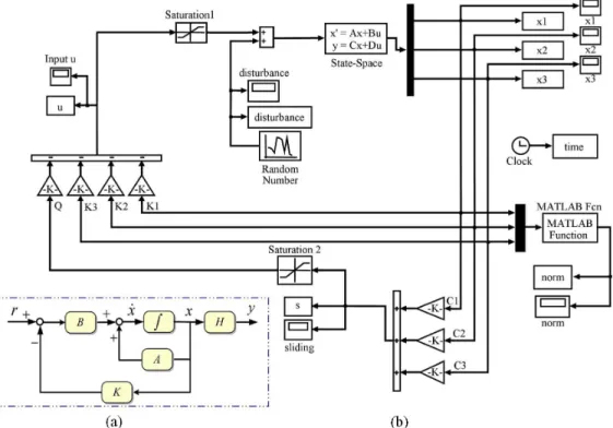
V. SIMULATION ANDEXPERIMENTALRESULTS The virtual eigenvalue method in SMC is utilized to simulate time response of a compact OISA in a POS, and the simulation diagram by using SIMULINK is de-picted in Fig. 2(b). The eigenvalues of the first and second
axes are and ,
re-spectively. The gain matrix of the first and second axes are estimated as:
and , respectively.
The sliding vector can be obtained from (9), and
and ,
respectively. Thus, the sliding functions of dual axes, and , can be obtained from (10).
The hardware control block diagram whose schematic is shown in Fig. 3 for position control of a compact OISA in a POS. The SMC algorithm is written in PC language to obtain fast dynamic characteristics of a compact OISA. A PC-inter-faced data acquisition card with two-channel analog/digital converters (ADC) acquires signals of Hall and gyro sensors, and then let these two position signals pass through the filters and amplifiers before entering ADC. The transient and steady-state response of dual axes in simulation and experiments are shown in Fig. 4. As a result, the SMC algorithm works well despite system uncertainty and external disturbance. The settling time of dual axes are converged within 0.2 s while the dual axes of the movable platform of a compact OISA move at 0.5 mm
YU AND LIU: SLIDING MODE CONTROL USING VIRTUAL EIGENVALUE METHOD 4077
Fig. 2. (a) Block diagram of state feedback control. (b) Block diagram of simulation by adopting SIMULINK.
Fig. 3. Hardware control block diagram of a compact optical image stabiliza-tion actuator in a photographing optical system.
Fig. 4. Simulation and experimental results for (a) the first axis and (b) the second of a compact optical image stabilization actuator in a photographing optical system.
stroke, and the time response of simulation and experiments are matched.
VI. CONCLUSION
In this paper, a sliding mode control (SMC) law using vir-tual eigenvalue method is adopted to achieve fast time response and accurate position despite vibration from external jitter and friction of compact optical image stabilization actuators (OISA) in a photographing optical system (POS). When the target po-sitions of dual axes of OISA are at 0.5 mm, the time response
of dual axes by adoption SMC law are converged within 0.2 s settling time. The experimental results show that the control per-formance matches the design requirements. In consequence, the characteristics of the compact OISA can satisfy demands of the POS.
REFERENCES
[1] H. Okuda, M. Hashimoto, K. Sumi, and S. Kaneko, “Optimum motion estimation algorithm for fast and robust digital image stabilization,”
IEEE Trans. Consum. Electron., vol. 52, pp. 276–280, Feb. 2006.
[2] B. Cardani, “Optical image stabilization for digital cameras,” IEEE
Contr. Syst. Mag., vol. 26, pp. 21–22, Apr. 2006.
[3] K. Sato, S. Ishizuka, A. Nikami, and M. Sato, “Control techniques for optical image stabilizing system,” IEEE Trans. Consum. Electron., vol. 39, pp. 461–466, Aug. 1993.
[4] H. C. Yu and T. S. Liu, “Design of a slim optical image stabilization actuator for mobile phone cameras,” Phys. Stat. Sol. (c), vol. 4, pp. 4647–4650, 2007.
[5] Y. Okamoto and R. Yoshida, “Development of linear actuators using piezoelectric elements,” Electron. Commun. Jpn., vol. 81, pp. 11–17, 1998.
[6] H. C. Yu and T. S. Liu, “Adaptive model-following control for slim voice coil motor type optical image stabilization actuator,” J. Appl.
Phys., vol. 103, pp. 07F114-1–07F114-3, 2008.
[7] C. W. Chiu, P. C. P. Chao, and D. Y. Wu, “Optimal design of mag-netically actuated optical image stabilizer mechanism for cameras in mobile phones via genetic algorithm,” IEEE Trans. Magn., vol. 43, pp. 2582–2584, Jun. 2006.
[8] D. H. Yeom, N. J. Park, and S. Y. Jung, “Digital controller of novel voice coil motor actuator for optical image stabilizer,” in Proc. Int.
Conf. Contr., Automat. Syst. 2007, Oct. 2007, pp. 2201–2206.
[9] V. V. Chalam, Adaptive Control Systems: Techniques and
Applica-tion. New York: Basel, 1989.
[10] V. I. Utkin, Sliding Modes in Control Optimization. New York: Springer-Verlag, 1993.
[11] V. Sinswat and F. Fallside, “Eigenvalue/eigenvector assignment by state feedback,” Int. J. Contr., vol. 23, pp. 183–196, 1977.
Manuscript received March 03, 2008. Current version published December 17, 2008. Corresponding author: H.-C. Yu (e-mail: [email protected]).