Proceedings of the 2001 IEEE
International Conference on Robotics 8, Automation Seoul, Korea
.
May 21.26, 2001The Modeling and Control of the Cluster Tool in Semiconductor Fabrication Han-Pang Huang*, Che-Lung Wang**
Robotics Laboratory, Department of Mechanical Engineering National Taiwan University, Taipei, 10674 Taiwan.
Email:
TELIFAX: (+886-2) 2363-3875
*Professor and correspondence address **Graduate student
Abstract
A single wafer proces:;ing IC fabrication with flexible and distributed configuration is getting more important. The cluster tool is such an IC fabrication equipment. It consists of the cassette module, transport module, and process module. I n this paper, the model of a cluster tool is constructed using distributed colored timed Petri net (DCTPN). The emulator and controller of the cluster tool are further constructed. The standards of SECS, HSMS and GEM are used to develop the intelligent module controller. Finally, the web-based remote controller is developed and the SPC module is built in the cluster tool.
Keyword: cluster tool, distributed colored timed Petri net, intelligent module controller, webbased remote controller.
1. Introduction
The IC fabrication industry plays an important role in the rapid growth of information technology. A flexible, distributed configuration and single wafer processing IC fabrication is required for the short product lifecycle and quick product change. The cluster tool has multiple chambers with single-wafer process. It is a key for the customerized market. The cluster tool consists of the cassette module, transport module, and process module. Due to standardized control and mechanical interface, each module can be attached to a cluster tool and integrated into the cluster tool control system. Besides, the foundation of the cluster tool controller is the cluster tool module communication 1;CTMC) environment. The cluster tool controller and module controller can communicate over an Ethernet - TCPiIP network. However, the message transmitted from each controller is not in a standard format. The message format between the cluster tool controller and thi: module controller will be standardized using the intelligent module controller. The intelligent module controller employs agent technology to ensure message delivery and server loading balance. Based on the proposed intelligent module controller, the new coming module can t ' e quickly configured and integrated into the system.
The virtual manufacturing (VM) is getting popular in the Internet era. It can provide a total solution for short lifecycle and customerized production. One way to
model the behaviors of the cluster tool and run the simulation of the cluster tool.
On the other hand, the Internet -based manufacturing system is suitable for global and distributed manufacturing. The design, research and manufacturing need not be located at the same site. The web-based control is the key of Internet based manufacturing. A web-based control of the cluster tool will be proposed. Using the browser, the cluster tool can be controlled by the remote user.
2. Literature Review
The cluster tool is similar to a manufacturing cell. The cluster tool controller has to communicate with the fah host controller in the upper level and all modules controller in the lower level. Yung, Lee, Tom, and Moyne [ l ] proposed that the control structure best suited for semiconductor manufacturing was the hierarchical control structure. Numerous literatures used traditional or modified Petri net to model flexible manufacturing systems and assembly systems [2, 31. Kuo et al. developed an object-based distributed colored timed Petri Net (DCTPN) [4,5].
Many literatures discuss attributes and applications of the cluster tool. Mauer, Venkatesh, Lemmen and Igor [6] analyzed the behaviors an optimal performance of the cluster tool and the flexibility of a cluster tool. An up-todate factory should provide tele-monitoring and communicate with the enterprise immediately once there is an emergent event. Internet satisfies these requirements. The WWW (World Wide Web) technology on the Internet becomes a strong alternative to solve the problems in many domains [7]. Mozumder [8] proposed the framework of the statistical process control. Kuo et al. [4] addressed a CTPN-based SPC and -fault diagnosis models so that they could be integrated into the CTPN environment.
3. Distributed Colored Timed Petri Net Model of Cluster Tool Controller and Emulator
Modeling of the cluster tool using DCTPN and the characteristic behavior of the cluster tool has great benefits. The emulator is designed and implemented using DCTPN.
3.1. DCTPN Introduction
extensions: color attributes, time property, distributed modular design, communication module, and arc multiplier. This new kind of Petri net is called distributed colored timed Petri net (DCTPN). A distributed hierarchical DCTPN is an eleven-tuple structure, DCTPN
= (Pt, Tt, PO, TO, Pc, Pd, Tm, A, B, F, C), where Pt is a set of timed places; Tt is a set of timed transitions; PO is a set of immediate places; TO is a set of immediate transitions; Pc is a set of communication places; Pd is a set of COM server places; Tm is a set of macro transitions; A is a set of directed arcs; B is a set of inhibitor arcs; F is a set of interrupt arcs; C is the color set of transitions and places. The dcfinitioiis and theorems of DCTPN are given in [4]. The icon definition of the DCTPN is shown in Fig. 1.
Fig. 1 Icon Definition of the DCTPN 3.2. Structure of a Cluster Tool
A cluster tool consists of the cluster tool controller, transport module controller, process module controller, intelligent module controller, recipe management module, monitoring module, SPC module, in-situ metrology module, break down module, scheduling and dispatching module. Three process functions (RTCVDiPolysilicon, RTCVDNitride, and RTO) and one clean function are
integrated into a cluster tool.
3.3 Modeling of a Cluster Tool
DCTPN plays a major role to construct the cluster tool controller model. The intelligent module controller of a cluster tool can be modeled in terms of several individual modules Each module consists of communication agent module. The cluster controller can bc modcled in the superior DCTPN net Based on the sequencc diagram, the flow chart is easily constructed in Fig 2 and can be transformed into the DCTPN net. Fig. 3 and Fig. 4 shows the DCTPN models of the cluster controllcr in the upper part and lower part. In this work, the intelligent module controllers of the process and transport modules are constructed [4]. Fig. 5 shows the flow chart of the intelligent robot module controller, and its model is given in Fig. 6 The detailed robot type is not
included i n the Fig 6 due to the property of macro transitions T-02, T-07, and T-13. The robotscheduling program for either moving to destination position or rcturniiig to home position is determined by the place, P-15. The spccds of the robot movement, wafer pickup, and wafer place-down can be modeled by DCTPN subnets, including single end-effector robot (SEER) and dual-effector robot (DEER). The operation flow chart of
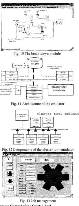
the DEER and SEER robots are described in Fig. 7. The DCTPN models of DEER and SEER robot motions are shown in Fig. 8 and Fig. 9. The cluster tool cannot work when the key module, such as transport module, is broken or under maintenance. Therefore, the maintenance behavior and the fault diagnosis of the cluster tool modules, e.g. the robot module, cassette module, and process modules, must be included in the DCTPN model. The activities of the fault analysis and machine maintenance are modeled in the intelligent module level. Fig. I O shows the break-down module. To analyze the failure modes and effects is an important thing to identify the various possible faults. For this reason, a fiult tree plays a major role in solving the problems. Using a fault tree, the various possible failure modes and effects can be easily identified. For the robot module, most fault conditions can be divided into four cases including servo, peripheral, vacuum state and controller. The fault message will be sent to the cluster tool controller through NTUNet and the fault problem will be identified. After solving the fault problem of the robot, the message of finish repair will be sent, and the robot can work normally again. 3.4. Design of an Emulator and Implementation of a Cluster Tool Controller
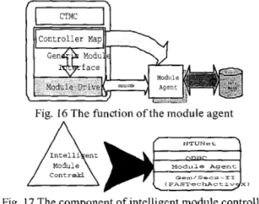
The emulator plays an important role in installation and optimization of the equipment allocation in the semiconductor factory. The cluster tool emulator provides a simulation solution for scheduling in advance and economizes testing time. The dynamic behavior of the cluster tool is very complicated since there are only one or two robots to transfer the wafer to the destined chamber or loadlock. Finding the best configuration of the cluster tool is the main goal to install the cluster tool. The emulator is an easy way to get the solution. The features of the dynamic behavior of the cluster tool can be classified into two parts: The product recipe detemiines the route of the wafers and the robot is a key factor to transfer the wafers to the destination place. The process modules influence the processing time of the wafers and decide the characteristic performance of the system. The DCTPN model indicates the characteristics of the cluster tool and is used as a referential warranty. The justification of the emulated program can be expressed in the model. The architecture of the emulator is shown in Fig. 1 I . The realization of the entire system is according to the DCTPN model as shown in Fig. 12. The cluster tool controller controls the Petri net models of the cluster tool, and is developed using Visual C++7M. In order to control the security of the information, the emulator controller can manage the user and set the user access level, which determines the access privilege within the system. In addition, the job can be managed according to the desired requirements, as shown in Fig. 13. The job includes moving wafers from a cassette, processing wafers in the process modules and placing wafers back into a cassette. The running option is to start the emulator of the cluster tool, as shown in Fig. 13.
Fig. 2 Operation flow of the cluster controller
Fia. 3 U m e r part of cluster tool controller
Fig. 4 Lower part of cluster tool controller from Cluster Controller
Move Robot Arm from Current Chamber to
Move Robor Arm from Destination Chamber to
Pickup Waferfrom
Startchamber Go H,nne
T H T - 1
Move Robot Arm from[=I
Deslinaticn Chamber to Clustei Controller Stan Chamber to
Destination Chamber
Fig. 5 Operation flow of an intelligent robot module
controller
Fig. 6 Intelligent transuort module controller
0 Deg 60 Deg
Fig. 7 The operation flow chart of the DEER and S W robots are described
Y ".E".
Fig. 8 DEER robot rotation model
____
__ __--
Fig. 10 The break-down module
Fig. 11 Architecture of the emulator
ool emluator
Fie. 12Comnonents of the cluster tool emulator
Fig. 13 Job management 4. Remote Control of the Cluster Tool
the architecture of the control system will be discussed. 4.1 Remote Control Architecture and Method
The reinote control application adopts three-tier architecture. The three4er architecture includes front-end presentation, logical computation, and data layer The frontend presentation layer shows data to the client. The logical computation layer storesiaccesses data and perform mathematical operations. All kinds of information i n the PC or workstation are stored by the data layer. The major advantage of the three-tier architccture is that every tier is independent. It is further The remote control method will be introduced and
elaborated below. Front End Presentation Layer: The Internet Explorer 5 01 is used as the browser. Logical Computation Layer. It may contain ITS, which can transform data to the form of HTML in the database using ASP and ActiveX control. Equipment (cluster tool) can use IIS to show the real-time data, sound and mage on the remote monitoring system Data Layer: SQL server can be used. The monitoring computer momentarily checks the control state table of the server, and compares the control table of the monitoring computer. If there is no corresponding counterpart, the monitoring computer performs the mapping statement. The users in the remote computer can connect to the specific homepage on the specific server, and change the corresponding state table in the ASP program or ActiveX control program, such as the NetmeetingTM object. The monitoring computer transforms the statement in the state table into the standard language of equipment communication, such as GEM, SECSII, and CTMC Eventually, the message is sent to the cluster tool controller by the monitoring computer Based on the NetmeetingTM object, which is the ActiveX control, the image and sound can be transferred from the factory to the remote side.
4.2 Webhased Remote Controller
The web-based remote controller sends the status of the cluster tool and the on-site image and sound to the remote browser The remote engineers can take action to handle the emergency and control the cluster tool controller in the factory In order to get the information from the factory, the CCD cameras and web-based control are required Therefore, the remote engineer can real-time control the cluster tool and the manager from the remote side can administrate the local operators in terms of critical condition. The level of the web-based controller is
shown in Fig 1 1 . Using ASP technique, the login data can
be checked and stored in the database of the server as shown in Fig. 14. After entering the controller, the user can manage the jobs of the cluster tool and run the cluster tool controller on the remote side through internet. The server of the real -time controller, including ActiveXTM control objects, is implemented on the IISrM sever. The user from the remote side can launch the local control programs and fully operate the function of the cluster controller, as shown in Fig. 15. Due to the limited network bandwidth, there exists a time delay in transmitting images and sound. The serious time delay may block some alarms from receiving. In order to overcome this problem, the situation table of the cluster tool is constructed. Therefore, the text can be quickly transferred and the remote user is easily aware of the information from the cluster tool.
Fig. 15 Control from the remote side
5. Design and Implementation of the Intelligent Module Controller
The intelligent module controller will be constructed The agent based module controller is developed using DCOM techno1 ogy.
5.1. Agent Based Intelligent Module Controller
The cluster tool consists of process modules, transport modules and cassette modules All modules communicate in CTMC envii.onment and have many types of message flows. The intelligent module controller has to coordinate the six types of message flows Using the agent technology, the intelligent module controller can ensure the loading balance and message delivery The architecture of the intelligent module controller is flexible and can be easily reconfigurecl due to the characteristics of DCOM.
The intelligent module controller meets the CTMC standard and consists of control applications. The decision logic built in the control applications can control the status of the process module The intelligent module controller can specify a set of SECSII messages to support the CTMC servicl:. Moreover, the agent technology is applied to the intelligent module controller and coordinates the message iri the cluster tool controller The module agent communicates with the cluster tool controller in the upper level and sends commands to the process module controller in the lower level, as shown in Fig 16 The command format of the module agent I S
SECSII The operation procedure of the module agent is described as follows. First, the module agent identifies the cassette modules, transport modules and process modules Second, the module agent connects to the database in order to obtain the data from the scenario table. After getting the data, the module azent determines the order of the process sequence The way to find the order of the process sequence is to check the scenario identity and decide the scenario number, which indicates the beginning of the message flow. According to the flow chart, the module agent is developed using DCOM technology. Based on DCOM technolcgy, the agent module is constructed as a DCOM server and executed on any registered server computers. Therefore, the DCOM server can achieve the loading balance of the server computers that run programs to control the process module. 5.2 Realization of an Intelligent Module Controller
The model of the intelligent module controller is constructed using the DCTPN The module agent is constructed as the DCOM server using Microsoft Visual
C++ 6.0 and Active Template Library '3.0 (ATL). The user can use CTPNDesign program to setup the DCOM server and run the DCOM server on any server computet: The types of the DCOM server, including process module, robot module and cassette module, is chosen by the user.
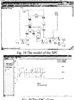
The intelligent module contioller includes the NTUNet, ODBC driver, ActiveX control component and the module agent, as shown in Fig. 17. The intelligent module controller communicates with the process module based on SECS-I1 and GEM standards, which are AtiveX control of FASTechTM. All scenarios of the process module and the intelligent module controller follow the scenario table and behavior table In this work, SECSIMProTM or the process module. simulator simulates the real process module The process module emulator is constructed using FASTechTM ActiveX Control and modified according to the type of the process module. First, the message from the cluster tool controller is sent to the process module. Then, the process module retrieves the messages and handles the messages. Before processing the wafer, the recipe must be confirmed and loaded into the process module controller. If the setup of the process module is ready, the process module starts to process the wafer in the chamber The process module will retrieve the SECS-I1 messages and responsd it t o process the wafer.
Fig. 16 The function ofthe module agent
A
Fig. 17 The component of intelligent module controller
5.3 SPC Module Architecture
The purpose of the SPC system is to check whether the product satisfies the specification and tolerance. If the result does not meet the tolerance, the SPC system keeps track of the flaw of the product. The system architecture of the SPC module is depicted in Fig. 14. After the data is collected from factory, the SPC system stores historical data into the database. The lower bound and upper bound of the control chart can be calculated in terms of the historical data.
The SPC module collects the data from process modules and computes the data in order to determine the condition of the process module. Then, the expert system identifies the assignable causes, adjusts the process and eliminates the process variance. Besides, the SPC module has other functions to call the process module controller and communicate the message to it.In this study, the SPC activities are modeled by the DCTPN. First, the SPC
module retricves the characteristic data from the database and initializes the data. Then, the module finds out the process capability parameters and sets up the control limit. Finally, the module specifies the chart analysis and informs the process control.
5.4 Model and Realization of the SPC Module
The DCTPN model of the SPC module is coiistructcd and shown in Fig. 18. All SPC module can be easily attached to the process module and acquire the data from the database. The SPC module server is implemented by DCOM technology using ATL 3.0. The client can retrieve the data from the DCOM server. Due to DCOM technology, the characteristic benefits are included i n thc SPC server The SPC server can achieve the loading balance of the server computers that run programs to control the process module. The user can also use CTPNDesign program to run the DCOM server on any server computer. The control chart of the SPC tool IS
applied to the process module as shown in Fig. 19
-I
Fie. 18 The model of the SPC
- -
Fig. 19 The SPC client 6. Conclusions
The flexible cluster tool model was constructed in detail using DCTPN. The model can be easily reconfigured to fit in the real status of the cluster tool setup, including the robot module, process modules and break-down module. Each module can incorporate with the breakdown module. The associated fault tree of the break-down module is constructed by DCTPN. Based on the DCTPN modeling and simulation environment, the cluster tool can be easily reconfigured, modeled, controlled and evaluated. The cluster tool controller and web-bascd controller were developed. The computer in the rcmote side can easily control the cluster tool controllcr through intranet or nternet. Other computers through the WWW browser can control the computer that installs the cluster tool controller The intelligent module
controller was constructed based on agent technology and DCOM technique. Using the agent technology, the intelligent module controller can ensure the loading balance and message delivery. The intelligent module controller communicates with the module emulator in terms of SECS -11 protocol and GEM specification through HSMS or SECS-I. Finally, the model of SPC module was developed for quality control. The SPC server using DCOM technique can decide the control rules and take action to the status that is out of the control.
References
[ l ] J.R. Moyne, H. Etemad and N. Najafi, “A Monitoring And Diagnostics System For A Plasma Etching Cell,”
IEEE/SEMI Advanced Semiconductor Manufacturing Conference, pp.48-53, 199 I.
[2] G.H. Hu, Y.S. Wong and H.T. Loh, “An FMS Scheduling and Control Decision Support System Based on Generalised Stochastic Petri Net,”
International Journal of Advanced Man~ifucturing Technology, Vol.10, No.1, pp.52-58, 1995.
[3] H.P. Huang, and P.C. Chang, “Specification, Modeling and Control of a Flexible Manufacturing cell,” International Journal of’ Produce Research,
[4] C.H. Kuo, “Development of Distributed Component Based Manufacturing System Framewok,” Doctoral
Dissertation, Department of Mechanical Engineering
National Taiwan University, 1999.
[5] C.H. Kuo, H.P. Huang and M.C. Yeh, “Object-Oriented Approach of MCTPN for Modeling Flexible Manufacturing Systems,“ tnternationul Journul of Advanced Munufucturing Technology, [ 6 ] B. Lemmen, C. Van, H. Roede, J.E. Rooda,
“Clustertool Optimization Through Scheduling Rule,”
IEEE Proceeding of Semiconductor Manufacturing Conference, pp.89-92, 1999.
[7] J.C. Moon, “An Event Channel-Based Embedded Software Architecture for Developing Telemetric and Teleoperation Systems on the WWW,” IEEE Proceeding of International Conference on Intelligent Robots and Systems, pp.224233,1999.
[8] P.K. Mozumder, C.R. Shyamsundar, and A.J. Strojwas, “Statistical Control of VLSI Fabrication Processes: A Framework,” IEEE Transaction on Semiconductor Manufacturing, Vol.1, No.2, pp.62-71, May, 1988.
V01.30,N0.ll,pp.1515-1543, 1989.