PerkinElmer Taiwan 珀金埃爾默(股)公司
1
「
光電材料暨檢測研討會
」
分子光譜
於光電材料上的應用
© 2009 Perkin Elmer Tiffany Kang 康瑜容Tiffany.Kang@perkinelmer.com PerkinElmer Taiwan 珀金埃爾默股份有限公司什麼是分子光譜?
4000 400 cm-1 12,820 50,000 Increasing Wavelength Increasing Energy Radio Micro FIR IR NIR UV X-ray Gamma 25 000 nm 2500 780 380 200 K層電子 外層電子 分子振動 分子轉動 UVS-2分子光譜的組成
分光光譜儀主要元件:
燈源:
陶瓷燈源、氙燈、鎢鹵燈、氘燈、雷射…..
光學元件:
稜鏡、光柵、干涉儀…..
偵測器
DTGS
MCT P t di d
PMT
偵測器:
DTGS、MCT、Potodiode 、PMT….
使用分光光譜儀目的在於對化合物之定性定量
Beer’s Law A=εbC分光光譜儀使用上優點:
樣品無需前處理
不破壞樣品
Detector
+
+
分析時間快速
UVS-3Part (I)—
平面顯示器相關材料
© 2009 Perkin ElmerPerkinElmer Taiwan 珀金埃爾默(股)公司
3
光電產業光譜量測的需求
ITO ‐ 穿透率(%T)及反射率(%R)
背光膜 – 反射率(%R)
LCD LCD產業的量測需求產業的量測需求 5(
)
彩色濾光片 – 穿透率(%T)及CIE參數
Polarize filter – 穿透率(%T)及極化率(Polarization Factor)
最新的UV/Vis & UV/Vis/NIR光譜量測設備介紹
紫外光/可見光分光光譜儀 Lambda 650光譜儀主體
光譜儀主體
Wavelength : 190~900nm UV/Vis resolution : 0.17nm Lambda 850 Wavelength : 175~900nm UV/Vis resolution : 0.05nm 紫外光/可見光/近紅外光分光光譜儀 6 紫外光/可見光/近紅外光分光光譜儀 Lambda 950 Wavelength : 175~3300nm UV/Vis resolution : 0.05nm NIR resolution : 0.20nmInside the Lambda Series
7
PerkinElmer Taiwan 珀金埃爾默(股)公司
5
光譜量測技術介紹
配件部分
© 2009 Perkin ElmerWhen the incident light thought a material …
UVS-10穿透附件
單一入射角 可變入射角(manual type) 0~60 degree 0~360 degree 可變入射角(Auto type) Defined by user 0~360 degree 0~360 degree rotation stage rotation stage S S Light Light••
量測樣品種類
量測樣品種類
: color filter, polarize filter, ITO glass
: color filter, polarize filter, ITO glass
••Polarize need or not ???
Polarize need or not ???
UVS-11
Solution 1 – color filter analysis (any filter)
PerkinElmer PerkinElmer Lambda Lambda Transmittance Transmittance holder holder Result text Result text 650/850/950 650/850/950 Color Color software software spectrum spectrum Color Color method method Result graph Result graph UVS-12PerkinElmer Taiwan 珀金埃爾默(股)公司
7
Polarize light ??
量測 Polarize filter 時
量測穿透及反射入射角大於10度時 光源在經偏極化前需為random light (depolarize light)
light (depolarize light) 0~360 degree 0~360 degree UVS-13
Solution 2 – Polarize filter
Lambda 650/850/950 Lambda 650/850/950 Polarizer Driver Polarizer Driver & & holder holder CBDepolarizer CBDepolarizer單體
單體
//
偏光片組量測
偏光片組量測
自動尋找直交及平行所對應的角度 測量偏光片在不同入射角度下的穿透率(0~360 degree) color color Software Software Sample holder Sample holder 偏光片偏光片11 偏光片偏光片22 14 ( g ) 自動計算極化率 P =配向膜
配向膜是控制LCD顯示品質的關鍵材 料,用於液晶顯示器上下電極基板 的內側,目的在控制液晶分子排列 方向。 0~360 0~360 degree degree 0~360 0~360 degree degree 15 Lambda 650/850/950 Lambda 650/850/950 Polarizer Driver Polarizer Driver & & Sample holder Sample holder CBDepolarizer CBDepolarizer配向膜錨定能量測
配向膜錨定能量測
Solution 3
– 配向膜
Software Software Rotation Rotation Stage Stage 偏光片 偏光片 22 偏光片 偏光片11 樣品樣品 自動定位cross角度及樣品與光軸垂直 轉動偏光片2,找到光通過的最小角度為θ1。 16 轉動樣品 φ角(user defined)。 轉動偏光片2,找到光通過的最小角度為θ2。PerkinElmer Taiwan 珀金埃爾默(股)公司
9
Lambda 650/850/950 Lambda 650/850/950
Rotation Stage & Rotation Stage & Function Generator Function Generator
ASSP
Test Cell &
視角特性量測
Solution 4 – Test Cell
量測不同入射角及不同輸入電壓下的穿透圖譜 Software Software Sample holder Sample holder 波形產生器 波形產生器 樣品槽樣品槽 偏光片+彩色率光片+液晶+TFT 17 計算色度座標值 XYZ, Lab, Yxy
Solution 5 – ITO glass
Lambda Fiber stage ASSP Software 650/850/950 Sphere detector Common Beam Depolarizer
Fiber
Fiber
Stage
Stage
18ITO
ITO
glass
glass
反射模式量測
© 2009 Perkin Elmer 鏡面反射(specular reflectance) AR (Anti Reflectance) HR (High Reflectance) Specular Reflectance-相對反射附件(1) 單一固定角度: near normal angle 6,45,80 degree6 degree
6 degree 45
45 degree
degree
PerkinElmer Taiwan 珀金埃爾默(股)公司
11
Specular Reflectance-相對反射附件(2) 可變角度: 15 to 70 degree 21 Specular Reflectance-絕對反射附件(1) 單一固定角度 (AR / HR) VNtype: near normal angle 8,15,30,45,60 degree
Specular Reflectance-絕對反射附件(2)
單一固定角度 (HR)
VWtype: near normal angle 7.5
23
VW variable angle absolute Accessory (3)
VWaccessory shown
with polarizer installed
Laser alignment makes
setup quick and easy
24 +/
PerkinElmer Taiwan 珀金埃爾默(股)公司
13
New URA accessory (4)
8 to 70 degree8 to 70 degree
Full automatic Full automatic
25
散射模式量測
© 2009 Perkin Elmer
散射反射(diffuse reflectance)
Integrating Sphere - 積分球
60mm Integrating Sphere
Spectralon coating inside
PMT & PbS detector R fl t ( 8 d Reflectance ( 8 degree incident angle) Transmittance 0 degree incident angle Yindex measurement Reference port Reference port (front) (front) 28 穿透樣品座 穿透樣品座 Reference port Reference port (back) (back) 反射樣品座 反射樣品座
PerkinElmer Taiwan 珀金埃爾默(股)公司
15
150MM SPHERE – Haze
••150 150 mm Diffuse Reflectance Integrating mm Diffuse Reflectance Integrating Sphere
Sphere
••Center Mount Clip and Jaw StyleCenter Mount Clip and Jaw Style
••Small Spot KitSmall Spot Kit
29
Part (II)—
太陽能相關材料
Solar Energy 的利用
太陽能的應用 Broad categories of solar energy applications
儲能裝置Energy Conservation
建築玻璃Architectural glass
建築玻璃Architectural glass
產能裝置Energy Production
聚光用途 Solar concentrators
太陽能電池(光伏) Photovoltaics
光熱收集器 Solar Thermal Collectors
UVS-31Photovoltaics Cell
UVS-32PerkinElmer Taiwan 珀金埃爾默(股)公司
17
Photovoltaic Cell
UVS-33What a UV/VIS/NIR Spectrometer for ?
Measure …
穿透 Transmission
Total or Diffuse Transmission
反射Reflectance
Specular Reflectance Total or Diffuse Reflectance
吸收Absorbance
UVS-34為何使用積分球附件?
© 2009 Perkin Elmer
Some Causes of Sampling Error
Poor parallelism
Poor parallelism Rough surfaceRough surface
Poor surface Poor surface finish finish Internal Internal cloudiness cloudiness Internal distortion Internal distortion Thick samples Thick samples UVS-36
PerkinElmer Taiwan 珀金埃爾默(股)公司
19
Integrating Spheres – What Type of Samples?
Glass Coatings Filters Scattering liquids Cosmetics Architectural Glass Powders Paints Plastics Semiconductor Optics Automotive Glass Inks Paper Thin Film Coated Glass Liquid crystals Crystals Precious stones Sunglasses Ceramics Clothing Contact lenses UVS-37What type of measurements?
%T Diffuse %T Solar Direct Transmittance Solar Direct Reflectance Variable Angle %T Absorptance %R Diffuse %R Specular %R Total %R H Solar Direct Absorptance Light Transmittance (Solar) Light Reflectance (Solar) UV Transmittance (Solar) UVA, UVB Thin Film Thickness S d l i i Haze Opacity CIE Color S and P Polarization UVS-38穿透的量測
直線穿透
Normal Transmittance
Transmittance Measurements散射穿透
Diffuse Transmittance
UVS-39Integrating Sphere – Transmission Measurements
Simplified diagram of an Integrating Sphere Accessory. Note reference beam path not shown. UVS-40PerkinElmer Taiwan 珀金埃爾默(股)公司
21
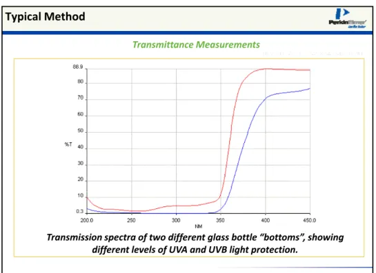
Typical Method
Transmittance Measurements Transmission spectra of two different glass bottle “bottoms”, showing different levels of UVA and UVB light protection. UVS-41反射量測 Specular and Diffuse Reflectance
Illustration of Specular and Diffuse Reflectance
Specular and Diffuse Reflectance
Both Diffuse and Total Reflectance can be measured directly with an integrating sphere
• 散射反射 Diffuse Reflectance散射反射 ff f measurements require that the specularq p light component be excluded
• 全反射 Total Reflectancemeasurements require that the specular light component be included
• 鏡面反射 Specular Reflectancecan be indirectly determined by subtracting the diffuse component spectrum from the total component spectrum spectrum. UVS-43
Diffuse Reflectance
Diffuse reflectance is measured on an integrating sphere by Diffuse reflectance is measured on an integrating sphere by placing the sample at the reflectance port (8 placing the sample at the reflectance port (8°°) with the ) with the specularspecular port in an open positionport in an open position
PerkinElmer Taiwan 珀金埃爾默(股)公司
23
Total Reflectance
Total reflectance is measured on an integrating sphere by Total reflectance is measured on an integrating sphere by placing the sample at the reflectance port (8 placing the sample at the reflectance port (8°°) with the ) with the specular port in the closed position specular port in the closed position UVS-45鏡面反射 Specular Reflectance的計算
Specular Reflectance Measurements Specular %R Curve Specular Reflectance Calculation with the PELA 1000 of a pink colored ceramic tile. The measured total reflectance spectrum minus the diffuse spectrum yields the specular reflectance of the sample.Total and Diffuse %R Curves Specular %R Curve
吸收的量測 Absorbance Measurements
吸收值 Absorbance: The percentage of energy incident on a specimen that is not directly transmitted or reflected. Wh li ht i i l lid t f th li ht i fl t d t i When light impinges on a clear solid, part of the light is reflected, part is transmitted, and part is absorbed by the material. This expression is often described as…T + R + A = 1
%Absorbance = 100% ‐ Direct Transmission ‐ %Reflected
Absorbanceis indirectly measured with an integrating sphere by obtaining the %R and %T spectra of the specimen. The absorbance is then calculated from the two spectra. UVS-47
吸收的計算 Typical Application
Absorptance Measurements Absorptance Calculation from %R and %T Spectra of PVC Exterior Covering using the Advanced Spectroscopy Software Package UVS-48PerkinElmer Taiwan 珀金埃爾默(股)公司
25
The application was to characterize a silicon photocell wafer The overlaid spectra shows the hemispherical reflectance andSolar Cell ‐ measured with Integrating Sphere
p transmittance of the wafer at 8° incidence (reflectance) and normal incidence (transmittance) over the solar range from 200 nm ‐ 1300 nm. With a highly scattering sample such as a silicon wafer, an i i h i integrating sphere is necessary to measure the scattered transmittance. UVS-49 Solar Cell ‐measured with the Center Mount 同時量測 Transmittance及 Reflectance The graphic shows the change in b ti f l ll t 10° absorption of a solar cell at 10 , 20°, 30°, 40°, 50°, and 60° incidence angles with hemispherical collection. Using the optional clip style center mount for the 150 mm Integrating Sphere. h h h h The graphic shows the measurement in absorption (AP = 1‐T‐R). We have now the possibility to calculate the thickness of any coating over the silicon. The coating can be either a protective film or an anti‐reflecting coating. UVS-50Solar Glass
Solar glass 的特性
Low iron glass (presence of iron makes glass green) 高穿透high sunlight transmission eg. super white solar glass 低反射low reflectivity to the sunlightSolar glass are used as the cover glass panel of PV cell and solar‐
powered water heaters
Solar glass的厚度
將會影響可見光visible range (380‐780 nm)穿透度 同時會影響熱性質 h l d i i d i i i 同時會影響熱性質 thermal conductivity and emissivity of the glass Good transmittance through solar glass of solar module UVS-51 “Patterned” Solar Glass – Trapping of Light Some solar glass are just plain, some have a sandy smooth texture and some even prismatically patterned to promote adhesion as well as to allow higher transmission at acute incident angles. Besides transmission, reflection and haze measurement the glass become important as well. Clear Hazy External reflection at a glass surface (n=1.52) showing s‐ and p‐ polarized components UVS-52PerkinElmer Taiwan 珀金埃爾默(股)公司
27
Solar Glass – Light Trapping with Anti‐Reflection Coating
External reflection at a glass surface (n=1.52) showing s‐ and p‐polarized components Representation of a single layer anti‐reflection coating Single layer MgF2 anti‐reflection coatingReproduced from Melles Griot 1998 UVS-53
Antireflective coating – effects on different wavelengths
6.0 7.00 Anti reflection coating on glass Anti reflection coating on glass 2.0 3.0 4.0 5.0 %R 600.0 700 800 900 1000 1100 1200 1300 1400 1500 1600.0 0.00 1.0 nm UVS-54Integrating Sphere – Thin Films Measurements
Transmission spectrum of front
Reflection spectrum of surface of surface of alloy coated thin film
solar glass
Reflection spectrum of surface of alloy coated solar glass surface
Reflection spectrum of uncoated glass side of alloy coated solar glass surface Transmission and reflection measurements are useful for quality control and specification UVS-55
霧度量測 Haze Measurement
Procedure based on ASTM 1003‐92 “Standard Method for Haze
and Luminous Transmittance of Transparent Plastics”
用以了解有多少Diffuse transmittance的比例
Haze用以了解有多少Diffuse transmittance的比例
Haze = [(T4/T2) ‐ (T3/T1)] x 100% where…Measurement Position A Position B
T1 No Specimen White Standard T2 Specimen White Standard T3 No Specimen Light Trap T4 Specimen Light Trap Patterned solar glass UVS-56
PerkinElmer Taiwan 珀金埃爾默(股)公司
29
Integrating Sphere – Haze Measurements
UVS-57
Haze Calculations
Integrating Sphere – Optical Transmission Haze Measurements of Polysilicon Coated Solar Glass 20 25 30 35 40 45 50 55 60 65 70 75 80 85 90 95 100.0 %T Sample 1-1
Transmission of smooth front surface of solar glass sample F-1
Transmission of smooth front surface of solar glass sample F-2
Haze = [(T4/T2) ‐ (T3/T1)] x 100% 15 20 25 30 35 40 45 50 55 60 65 70 75 80 85 90 95 100.0 %T T2 T4 F-1 Haze measurement 300.0 400 500 600 700 800 900 1000 1100 1200 1300 1400 1500 1600 1700 1800 19002000.0 0.0 5 10 15 nm 15 20 25 30 35 40 45 50 55 60 65 70 75 80 85 90 95 100.0 %T T4 T2 F-2 Haze measurement g p
Polysilicon coated solar glass Polysilicon coated solar glass
300.0320340360380400420440460480500520540560580600620640660680700720740760780800.0 -6.8 0 5 10 nm T3 T4 Illuminant:A Sample Haze % F‐1 9.10 F‐2 21.24 300.0320340360380400420440460480500520540560580600620640660680700720740760780800.0 -6.8 0 5 10 nm T3 Haze calculations are especially useful for quality control and specification purposes UVS-59
Measuring the Solar Transmission and Reflectance of Materials
太陽光穿透特性
“Solar” absorbance “Solar” reflectance “Solar” transmittance將太陽光的頻譜加權計算
The solar transmittance, reflectance, or absorbance is determined by calculating a weighted average with a standard solar irradiance波長範圍
Measurements of spectral near‐normal hemispherical transmittance (or reflectance) are made over the spectral range from 300 to 2500 nm. UVS-60PerkinElmer Taiwan 珀金埃爾默(股)公司
31
Solar measurements ‐ Architectural Glass
Recent developments in coating techniques have allowed builders to use l t i l hi h ti i t glass as a material which participates actively in heating and cooling control. Efficient window design incorporates coated glass in a double or triple pane configuration. The transmission of visible light, total solar energy and longer wave thermal radiation can be longer wave thermal radiation can be controlled within wide limits to reduce energy consumption for the regulation of temperature in a building. UVS-61UV/VIS/NIR Spectra of Architectural Glass
80 90 100 VISIBLE (LIGHT) NEAR INFRARED (HEAT) 10 20 30 40 50 60 70 %T UV The energy distribution within the solar spectrum is approximately 2% UV, 47% visible, and 51% infrared. Over 50% of the total solar energy that reaches Earth is in the near infrared portion of the energy spectrum 200 400 600 800 1000 1200 1400 1600 1800 2000 2200 2500 0 10 nm Uncoated glass UV protection coat Low E coat, moderate solar gain Low solar gain coat UVS-62Ratings for Architectural Glass
National Fenestration Rating Council (NFRC.org) U‐factor: Indicates the rate of total heat transfer through a window and its frame (without sunlight). Solar heat gain coefficient (SHGC): Derived from a solar weighted spectrum of UV/VIS/NIR light transmitted through a window.Visible transmittance (VT): The amount of Visible transmittance (VT): The amount of VIS light transmitted. These items are rated on a scale of 0 to 1. UVS-63 ASTM, EN, and ISO Methodologies for Solar Measurements ASTM E 903‐96 ASTM E 424 71
Standard Test method for Solar Absorptance, Reflectance, and Transmittance of Materials using Integrating Spheres
Standard Test Method for Transmittance and Reflectance
ASTM E 424‐71 ASTM E 490 ‐73 ASTM E 891‐87 ISO 9050 / EN 410
Standard Test Method for Transmittance and Reflectance (Terrestrial) of Sheet Materials
Standard Solar Constant and Air Mass Zero Solar Spectral Irradiance Tables
Standard Tables for Terrestrial Direct Normal Solar Spectral Irradiance for Air Mass 1.5
Glass in building - Determination of light transmittance, solar direct transmittance, total solar energy, transmittance and ultraviolet transmittance, and related glazing factors.
PerkinElmer Taiwan 珀金埃爾默(股)公司
33
Solar Spectral Curve
UV VIS NIR UVS-65Description of Air Mass AMx
The Air Mass number is the distance of the sunlight through the atmosphere longer than the vertical distance. Sunlight passing through the atmosphere is absorbed by water vapor and carbon dioxide as well as scattered by the atmosphere. AM1 is of lower intensity and has absorption bands compared to AM0 AM1 AM0 EARTH AM1,5 ATMOSPHERE UVS-66Architectural Glass Calculations
Normal, Double, Triple Glazing Light Transmission UVB Transmission Color Rendering (Ra) Light Transmission Light Reflectance Light Absorptance Solar Transmission Solar Reflectance Solar Absorptance Solar Factor / Glazing Factor
Solar Output per unit area (Os) Solar Response (Rs) Convolution Solar Factor / Glazing Factor UV Transmission UVA Transmission UVS-67
Architectural Glass Calculations
Solar Distributions • Global • Global 2 UV / IR Correction Thickness Compensation • Global 2 • Global 3 • P. Moon • Air Mass 1.5 • D65 • Solar • Solar 2 • UV Result Templates Automation UV • User definable –Unlimited number UVS-68PerkinElmer Taiwan 珀金埃爾默(股)公司
35
Solar Table for Air Mass 2
Relative spectral distribution of direct solar radiation S according to P.Moon for air mass 2 multiplied by the spectral bandwidth UVS-69Solar Measurements‐ Architectural Glass
Coated Low‐E Glass helps prevent heat from escaping in the winter, and helps prevent heat from entering in the summer. UVS-70Solar Measurements‐ Architectural Glass
Reflectance, Transmittance, and Absorptance of solar energy on double paned, air insulated architectural glass. UVS-71Architectural Glass
Diagram of a double pane window Low E coating Reflects long wave thermal radiation, affects the U‐factor.affects the U factor.
Solar control coating
Reflects or absorbs solar radiation, allowing visible light to be transmitted.
The coating design and its placement in The coating design and its placement in the window structure can be adjusted to achieve the desired effect.
PerkinElmer Taiwan 珀金埃爾默(股)公司
37
Solar Measurements‐ Architectural Glass
Example ‐ Performance Data for Architectural Glass UVS-73Architectural Glass Calculation Window
UVS-74Solar Reflectance ‐ Vinyl Siding Materials
1 T UVS-75Solar Reflectance ‐ Vinyl Siding Materials
UVS-76PerkinElmer Taiwan 珀金埃爾默(股)公司
39
Solar Reflectance ‐ Vinyl Siding Materials
ASTM Test Method E903 (1996)Method Name : AM150g.mgx Analyst : Method Info.:
Date: 02‐Mar‐04 Time : 03:53 PM Type: AM 1.5 W
Wavelength Range: 305.00 nm to 2494.00 nm
% Reflectance
Specimen Code UV Vis NIR Solar
_______________________________________________________________________ 2_573527.SP 7.66 25.76 51.14 37.32 2_573528.SP 6.67 19.77 51.09 34.26 2_573557.SP 10.62 47.23 69.36 56.79 2_573560.SP 10.45 47.97 72.51 58.64 2_573556.SP 10.18 56.12 71.23 62.12 2_573559.SP 10.57 58.46 75.99 65.56 UVS-77 New developments in glass products which combine light management and power generation. The technology allows glass windows to produce electricity via solar energy while allowing light to pass through. PV cells can also be integrated into walls and tiles as part of the buildings
or applied as films on s rfaces
New Solar Products ‐ Light Management and Power Generation
or applied as films on surfaces solar panel with a unique semitransparent finish used as a skylight integrated roof photovoltaic system designed to form a complete roof UVS-78太陽能電池
PV Cell Properties
Measurement
© 2009 Perkin Elmer
Band Gap and the Photovoltaic Effect
Conductor Semiconductor Insulator
C d i Band Gap eV Conduction Band Valence Band eV Band The band gap refers to the energy needed to move an electron from its ground state in the valence band to the conduction band.
PerkinElmer Taiwan 珀金埃爾默(股)公司
41
Band gap and the photovoltaic effect
Two or more very thin layers of semiconductor or conductor material can be stacked to
+ n p _ material can be stacked to produce a PV cell. Light absorbed near the p‐n junction creates voltage potential The incident photons must have energy equal to or slightly greater than the band gap energy for the absorbing material.
Transmission spectrum of Silicon
Thin crystalline Silicon 0 55 60.0 10 15 20 25 30 35 40 45 50 %T Free carrier absorption 1.1 eV 190.0 400 600 800 1000 1200 1400 1600 1800 2000 2200 2400 2600.0 0.0 5 nmEnergy Conservation & Renewable Energy Research
Developing technologies
• Solar technologies are of major interest
• Billions of dollars are being spent on research, worldwide
– Silicon no longer the only sourceSilicon no longer the only source
– Thin films are being developed to reduce cost – New manufacturing techniques to lower cost – Improvements in efficiencies is a major current driver – Weathering of the materials is an important consideration
Transmission spectrum of CdTe
Thin film of CdTe on glass 1.5 eVPerkinElmer Taiwan 珀金埃爾默(股)公司
43
Triple Junction Solar Cell Design
Material Symb Band gap (eV) Silicon Si 1.11 Germanium Ge 0.67 Aluminum phosphide AlP 2.45 Gallium(III) phosphide GaP 2.26 Gallium(III) arsenide GaAs 1.43 Gallium(III) nitride GaN 3.4 Gallium antimonide GaSb 0.7 Indium(III) phosphide InP 1.35 Indium(III) arsenide InAs 0.36 1.9 eV 1.4 eV 1.1 eV Substrate Three different materials allow absorption over a broad wavelength range.
Multi – layer thin films
Multiple layers of thin films can produce very complex Multiple layers of thin films can produce very complex interference patterns. interference patterns. Multilayer thin films Multilayer thin films Substrate SubstrateAluminium reflective coatings….
Construction of reflective Construction of reflective material
material
Visible spectra of component layers FilmStar Film
Thickness
C l l Visible spectra of component layers
…. have a multilayer composition
Softwares such asSoftwares such as FilmStarFilmStarcan help to do design and analysis of optical thin films of can help to do design and analysis of optical thin films of these multilayers.
these multilayers. Visit www.ftgsoftware.com Calculator