在網路處理器上實作差別服務時所衍生出之延展性和瓶頸之探討
50
0
0
全文
(2) Scalability and Bottlenecks of DiffServ over Network Processors Student: Yi-Neng Lin. Advisor: Dr.. Ying-Dar Lin Department of Computer and Information Science National Chiao Tung University. Abstract Network. processors. are. emerging. as. a. programmable. alternative to the traditional ASIC-based solutions in scaling up the user-plane processing of network services. They serve as co-processors to offload user-plane traffic from the original general-purpose microprocessor. In this work, we illustrate the process and investigate performance issues in prototyping a DiffServ edge router with IXP1200, which has one control-plane StrongARM core processor and six user-plane microengines, and stores classification and scheduling rules at SRAM and packets at SDRAM. The external benchmark shows that the system can support an aggregated throughput of 141Mbps of eight input ports, and 500 flows, which is extensible provided enough SRAM space, at one input port while conforming the PHB of each flow. Through internal benchmarks, II.
(3) we found that performance bottlenecks may shift from one place to. another. given. different. network. services. and. implementations. For simple forwarding services, SDRAM is a nature bottleneck. However, it could shift to SRAM or microengines if involving heavy table access or computation, respectively. We also identify the design pitfall of the hardware called the “MAC buffer problem”. Keywords: Network Processor, DiffServ, IXP1200, scalability, SRAM, SDRAM. Contents SCALABILITY AND BOTTLENECKS OF DIFFSERV OVER NETWORK PROCESSORS.......................................I ABSTRACT ...................................... II CONTENTS ..................................... III LIST OF FIGURES ................................ IV CHAPTER 1. INTRODUCTION .......................... 1 CHAPTER 2. ARCHITECTURE AND DEVELOPMENT ENVIRONMENT OF IXP1200 ...................................... 3 2.1 2.2. Architecture of IXP1200 ....................... 3 Development Environment ....................... 6. CHAPTER 3. D ESIGN AND IMPLEMENTATION OF DIFFSERV ON IXP1200 ............................................. 8 3.1 DiffServ Briefing............................. 8 3.2 Mapping DiffServ Components ................... 9 3.3 Detailed Packet Flow in IXP1200 .............. 12 3.4 Algorithm Implementations .................... 13 3.4.1 Classifier................................ 14 3.4.2 Scheduler................................. 17. CHAPTER 4. EXTERNAL BENCHMARK 4.1 4.2. AND. DESIGN PITFALLS ... 19. Benchmark Environment........................ 20 Functionality test........................... 21 III.
(4) 4.3 4.4. Scalability test............................. 28 MAC buffer problem........................... 30. CHAPTER 5. INTERNAL BENCHMARK 5.1 5.2 5.3 5.4. Simulation Simulation Simulation Simulation. AND. BOTTLENECK DISCUSSIONS33. Model............................. Result—Linear Search .............. Result—Range Matching ............. Result—Execution Coverage .......... 33 34 37 39. CHAPTER 6. CONCLUSIONS.......................... 41 REFERENCES: ................................... 43. List of Figures Fig. 1. Hardware architecture of IXP1200......................4 Fig. 2. Software architecture and development environment of IXP1200...........................................................7 Fig. 3. Inside a DiffServ edge device.............................9 Fig. 4 User-plane architecture of DiffServ edge router over IXP1200............................................................... 10 Fig. 5. Detailed DiffServ packet flow in IXP1200 13 Fig. 6. Fields in a rule ......................................................... 15 Fig. 7. Example and relative tables for lookup in Source IP dimension............................................................... 15 Fig. 8. Code of Policer and Marker ................................. 17 Fig. 9. Scheduler using DRR.................................................. 18 Fig. 10. Packets in a queue.................................................. 19 Fig. 11. Benchmark environment........................................... 21 Fig. 12. Throughput and loss rate with varying number of rules ......................................................................................... 22 Fig. 13 Aggregated throughput (Len=64bytes, worst case)................................................................................................. 23 Fig. 14. Loss rate with varying packet length (128-rules worst case)........................................................ 24 Fig. 15. Priority test (Len=64bytes)............................. 25 Fig. 16. Priority and bandwidth control test (Len=64byte, EF=62500pps)................................................. 26 Fig. 17. 4(EF, AF1-3) to 1 latency test (Len=64bytes, IV.
(5) EF=62500pps)................................................................................ 26 Fig. 18. Four-to-One fairness test (64rules, 4 Rx in one ME)............................................................................................ 27 Fig. 19. Four-to-One fairness test(64rules, 2 Rx in ME0, 2Rx in ME1)...................................................................... 27 Fig. 20. Single flow loss rate test............................... 28 Fig. 21. Scalability test (Len=64bytes, 100flows, BW=74400/100=744 frame/sec, normal case)............. 29 Fig. 22. Scalability test (Len=64bytes, 500 flows, BW=74400/500=148pps, normal case) ............................. 30 Fig. 23. Packet loss of different packet lengths in Linear Search ............................................................................. 31 Fig. 24. Receiving process of a packet........................ 31 Fig. 25. Software simulation model ................................. 34 Fig. 26. Summary of performance statistics.............. 35 Fig. 27. microengine statistics of Linear Search DiffServ ......................................................................................... 35 Fig. 28. Execution history of Linear-Search classifier..................................................................................... 36 Fig. 29. Microengine statistics of Range Matching classifier..................................................................................... 38 Fig. 30. The execution history of Linear Search in macro view..................................................................................... 39 Fig. 31. The execution history of Range Matching in macro view..................................................................................... 39 Fig. 32. Execution coverage of Linear Search DiffServ ............................................................................................................. 40 Fig. 33. Execution coverage of Range Matching DiffServ ......................................................................................... 40. V.
(6) Chapter 1. Introduction The increasing link bandwidth demands even faster nodal processing especially for the user-plane traffic. The nodal user-plane processing may range from routing table lookup to various classifications for firewall, DiffServ and Web switching. The traditional single-processor architecture is no longer scalable enough for wire-speed processing so that some ASIC components or co-processors are commonly used to offload. the. user-plane. processing,. while. leaving. only. control-plane processing to the original processor. Many ASIC-driven products have been seen in the market, such as the acceleration cards [1] for encryption/decryption, VPN gateways [2], Layer 3 switches [ 3], DiffServ routers [4] and Web switches [5]. While they indeed speedup the user-plane packet processing, they lack flexibility in reprogrammability and have a long development cycle which is usually nine months per ASIC. Network processors are emerging as an alternative solution to ASIC for providing scalable capability for user-plane packet. processing. while. retaining. programmability.. Nevertheless, it might not be powerful enough to replace the ASIC implementations which are application specific in designing the functional units such as a much wider memory bus, lower delay between functional units, and faster excution process, compared to instruction excution in processors. In 1.
(7) this study, we adopt IXP1200 (Internet Exchange Processor) [6] which is composed of one StrongARM core processor and six co-processors, referred as microengines, so that developers can embed the control-plane and user-plane traffic management modules into the StrongARM processor and. microengines,. respectively. Scalability concerns could be satisfied because of the six programmable microengines, with hardware threads, new instructions for networking purposes, and the extensible architecture of IXP1200. Tammo, Spalink, and Scott [ 7] demonstrated and evaluated the IXP1200 in IP forwarding and concluded that the SDRAM storing packets is the bottleneck. However, the evaluation results cannot be generalized for today’s complex services which need more SRAM table accesses and computing power. The objective of this work is therefore to implement a more sophisticated service, Differentiated Services (DiffServ), and identify possible performance bottlenecks and design pitfalls, if any, in IXP1200. There are three most important modules in DiffServ. classifier, leaky bucket and scheduler.. They are deployed into IXP1200 microengines and configured by the StrongARM. In benchmarking the implemented system, two topics are investigated.. First,. how. well. can. this. DiffServ. implementation scale, in terms of throughput and number of flows? Second, where are the potential bottlenecks of network processors, especially IXP1200’s, and their causes? We 2.
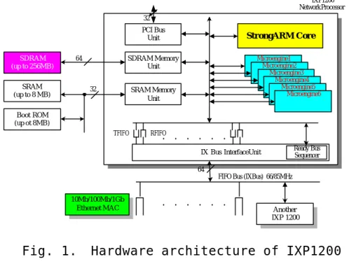
(8) anticipate that the exact bottleneck depends on the specific service and its algorithmic implementation. The paper is organized as follows. Chapter 2 briefly reviews the architecture and development environment of IXP1200. C hapter 3 presents the design and implementation of DiffServ over IXP1200. C hapter 4 and Chapter 5 illustrate the results. of. external. and. internal. benchmarking. through. experiment and simulation, respectively. Finally, Chapter 6 ends this work with conclusive remarks.. Chapter. 2.. Architecture. and. Development Environment of IXP1200 2.1. Architecture of IXP1200. Fig. 1 shows the hardware architecture of IXP1200. The 32-bit StrongARM, which is the core processor of IXP1200, is responsible for the initialization of the whole evaluation system and part of the packet processing. A Memory Management 3.
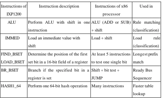
(9) Unit is also included to translate virtual addresses into physical addresses and control memory access permissions.. IXP1200 Network Processor 32. PCI Bus Unit SDRAM (up to 256MB). SDRAM Memory Unit. 64. SRAM (up to 8 MB). StrongARM Core. 32. Microengine1 Microengine2 Microengine3 Microengine4 Microengine5 Microengine6. SRAM Memory Unit. Boot ROM (up ot 8MB) TFIFO. . . . . . .. RFIFO. Ready Bus Sequencer. IX Bus InterfaceUnit 64 FIFO Bus (IXBus) 66/85MHz. 10Mb/100Mb/1Gb Ethernet MAC. Fig. 1.. . . . . . .. Another IXP 1200. Hardware architecture of IXP1200. The six microengines, which support four hardware contexts, i.e. threads, and 128 general-purpose registers and 128 transfer registers in each of them, are mainly used for receiving, manipulating, and transmitting the packets. Not shown in this figure is the Control Store in each microengine that holds microcode of up to 1 024 32-bit instructions. For networking purposes, microengines also support zero context switching overhead, single-cycle ALU with shifter, and other specifically. designed. instructions. for. bit,. byte,. and. longword operations. Table 1 lists some example instructions of IXP1200 for comparing with the ones of x86 processors.. 4.
(10) Instructions of. Instruction description. Instructions of x86. IXP1200 ALU. IMMED. processor Perform ALU with shift in one ALU (ADD or SUB) Rule matching instruction. + shift. (classification). Load an immediate value with. Load + shift. Load. shift FIND_BSET. Used in. (classification). Determine the position of the first At least 5 instructions Longest prefix. LOAD_BSET set bit in a 16-bit field of a register to test one single bit. match. BR_BSET. Branch if the specified bit in a Shift + bit test +. Ready Bus. register is set. Sequencer. HASH1_64. rule. JUMP. Perform one 64-bit hash operation Many instructions. Faster table lookup. Table 1. Some comparisons between instructions of IXP1200 and x86. The SRAM Unit, which is used for storing lookup tables and pointers in scheduling queues for packet forwarding, accesses SRAM via a 32-bit bus that provides a peak bandwidth of up to 400Mbytes per second and access time of 30 cycles [7]. The SDRAM Unit, which is used for storing mass data of packets, accesses SDRAM via a 64-bit bus that provides a peak bandwidth of up to 800Mbytes per second and access time from 40 to 55 cycles depending on the destination functional unit [7]. The 64-bit IX bus Interface Unit is responsible for servicing MAC interface ports on the IX Bus, moving data to and from the Receive and Transmit FIFOs. It provides a 4.2Gbps interface to MAC devices, meaning that it can afford 2.1Gbps of the input ports and output ports, respectively.. 5. In.
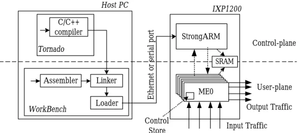
(11) addition, two IXP1200 network processors can be supported directly on the IX Bus without additional support logic. Operations of IXP1200 hardware components when handling packet-forwarding services can be described below. At boot time, the StrongARM loads boot image from Boot ROM and initializes other functional units, including loading the routing table into SRAM and microcode into microengines. The system is now ready to receive packets. When the Ready Bus Sequencer detects an incoming packet in a MAC port, it notifies the corresponding receiver thread to retrieve and store it in the RFIFO. After the receiver thread completes routing table lookup, it moves the packet to SDRAM waiting to be forwarded. A transmitter thread on another microengine later forwards the packet in SDRAM through TFIFO to another MAC port. There may be multiple receiver, transmitter, and scheduler threads. distributed. to. 6. microengines,. though. some. restrictions apply.. 2.2. Development Environment. Fig. 2 shows the software architecture of IXP1200. The software architecture consists of control-plane processing in StrongARM running under the VxWorks operating system [8] and user-plane processing in microengines running packet -processing threads. Though StrongARM can do the user-plane. 6.
(12) work, such unclearly divided workload distribution would lead to complex packet processing and thus low performance. The same thing happens otherwise for microengines with the control-plane work. A microengine can also communicate with StrongARM and other microengines using interrupt or signal mechanism, which helps in realizing the control/user plane architecture.. Host PC. Tornado. Assembler WorkBench. Linker Loader. Ethernet or serial port. C/C++ compiler. IXP1200. Control-plane. SRAM. ME0. User-plane Output Traffic. Control Store. Fig. 2.. StrongARM. Input Traffic. Software architecture and development environment of IXP1200. Also shown in Fig. 2 is the overview of the development environment. The IXP1200 programming can be divided into two aspects, which are StrongARM programming and microengine programming. While StrongARM programs are written in C/C++ under Tornado [8], microengine programs are written in assembly under WorkBench [ 9] for low-level packet processing capability. The compiled StrongARM executable is linked with. 7.
(13) object microcode compiled by the assembler, and then loaded into IXP1200 SRAM from which StrongARM initializes and loads microcode into the Control Store of microengines. The linked program can also be executed by the Transactor for pure software simulation. Besides, the StrongARM is big-endian and byte-addressable while microengines are little-endian and longword-addressable.. Chapter 3. Design and Implementation of DiffServ on IXP1200 In this chapter, we first give a brief introduction to DiffServ. Then we explain how to map DiffServ components onto IXP1200 program, followed by the detailed packet flow in the system. At last, we describe how to implement two major components, classifier and scheduler, in DiffServ with two existing algorithms, Multi-Dimensional Range Matching [11] and Deficit Round Robin [12], respectively.. 3.1. DiffServ Briefing. Differentiated Services (DiffServ) [10] mechanisms allow users to receive different levels of service from a provider 8.
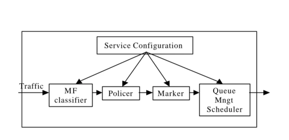
(14) to support various types of applications. Fig. 3 shows the functional components of a DiffServ edge device. According to the service configuration in a DiffServ edge node, packets are classified, according to multiple fields (MF), leaky bucket policed, and marked to receive a particular per-hop forwarding behavior (PHB), i.e. class-based scheduling, which is. Expedited. Forwarding. (EF). or. one. of. four. Assured. Forwarding’s (AF’s).. Service Configuration. Traffic. MF classifier. Policer. Marker. Queue Mngt Scheduler. Fig. 3. Inside a DiffServ edge device. The service differentiation of packets often takes effect in delay and loss rate. Packets of higher classes are more likely to be scheduled earlier than those of lower classes, and thus result in smaller latency and loss rate.. 3.2. Mapping DiffServ Components. Fig. 4 shows the software architecture of DiffServ and its corresponding task allocation on IXP1200. We insert six. 9.
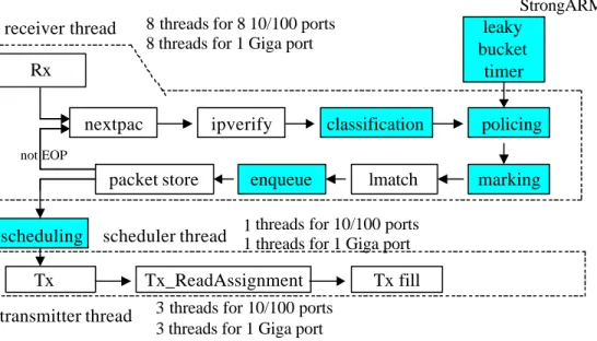
(15) DiffServ modules (the shadowed blocks) on top of the original software of simple IP forwarding. StrongARM. receiver thread. 8 threads for 8 10/100 ports 8 threads for 1 Giga port. leaky bucket timer. Rx nextpac. ipverify. classification. policing. not EOP. packet store scheduling. lmatch. marking. 1 threads for 10/100 ports. scheduler thread 1 threads for 1 Giga port. Tx transmitter thread. Fig. 4. enqueue. Tx_ReadAssignment. Tx fill. 3 threads for 10/100 ports 3 threads for 1 Giga port. User-plane architecture of DiffServ edge router over IXP1200. The DiffServ process is described below. After a packet header is received at a transfer register from an RFIFO and verified as legal, it is passed to the range-matching classifier, described in section 3.4.1, for the matching process. If the packet’s header matches one of the rules and is classified as, for example, EF traffic, we admit or discard it according to the policing bandwidth set in the rule. If admitted, it is marked with a DSCP (DiffServ Code Point) in the header. After longest prefix matching in routing table lookup, the packet is queued in the corresponding queue of the output port waiting for scheduling, i.e. the packet’s descriptor is enqueued in SRAM while the packet itself is. 10.
(16) stored in SDRAM. The scheduler thread chooses one transmitter thread and assigns it a port, which contains six queues (1 EF, 4 AF’s and 1 BE), to serve. The transmitter thread examines the queue with the highest priority to see whether there is a packet to be sent and whether it has enough quantum, which is used in Deficit Round Robin scheduling described in section 3.4.2, for that packet. If having enough quantum, the transmitter thread fetches the packet’s descriptor in SRAM and in turn the entire packet in SDRAM to TFIFO for output. Otherwise, it examines the next queue of lower priority for the packet and the corresponding quantum. The 24 threads are divided evenly into two groups, eight 10/100M ports and one giga port. Each group has 12 threads that are used as 8 receivers assigned to 2 microengines, 3 transmitters and 1 scheduler assigned to 1 microengine. Each 10/100M receiver thread is responsible for a specific 10/100M port, while 8 giga receiver threads serve one giga port. The transmitter threads, however, are not bound to specific ports. They output packets to ports according to the assignments from the scheduler thread. We use static task allocation instead of dynamic task allocation for the following reasons. First, the 1K Control Store of a microengine might not be large enough to hold microcode of two threads of different types, for example, receiver (1012 instructions) and transmitter (552 instructions) whose summed size of instructions exceeds 1024. However, transmitter and scheduler (144 instructions) whose 11.
(17) summed size is below 1024 can co-exist in one microengine. Therefore, we’d better group threads of the same type in one microengine. Second, if we choose dynamic allocation, the programming would be more complex and, since we cannot have a clear task division between threads, the communication overhead between threads or microengines would be large.. 3.3. Detailed Packet Flow in IXP1200. Fig. 5 illustrates the key components and the packet processing flow. The Ready Bus Sequencer periodically polls the MAC buffer and sets the receive flag in a global rec_rdy register when a packet comes. Once the. receiver thread. responsible for the MAC port detects the flag, it asks the Receive State Machine to move the packet, in units of 64-byte MAC packet, referred as MP which is a basic data unit in the system, from the MAC buffer into RFIFO. A FIFO, including RFIFO and TFIFO in the system, is used as an intermediate buffer for packets. Implemented as a 64-byte memory array, it could hold an MP to be stored in SDRAM or transmitted to a MAC interface. If an MP is a SOP (Start Of Packet), its first 32-byte containing the packet header is transferred into eight SRAM transfer registers, 4 bytes each, for classification, while the second half is directly stored in SDRAM.. 12.
(18) 1. Poll MAC buffer and set the rec_rdy flag of the port . . . . .. SDRAM. Thread0 of ME0. 5, 9 8 filter rules & routing table. SRAM. 7 6. 2. Poll rec_rdy of the port. SDRAM transfer registers (x8). 3. Issue a reference to Rx State Machine 4. Move MP to RFIFO. SRAM transfer registers (x8). 5. DRR per-port TFIFO. 10. per-port MAC buffer. per-port 3 RFIFO Receive 4 state machine 1. 2 rec_rdy. 5. If SOP, move half of the MP(header) to SRAM xfer regs for classification, half to SDRAM 6. Load rules into SRAM xfer regs (classification iteration) 7. Policing, marking, routing table lookup and enqueue (after classification) 8. Store the packet header to SDRAM. Ready Bus Sequencer. 9. Store the rest of the MPs to SDRAM 10. DRR scheduling and then transmit to TFIFO, MAC buffer. * If SOP, process from 1 to 8, otherwise from 1 to 4, then skip to 9. Fig. 5.. Detailed DiffServ packet flow in IXP1200. After classification, policing, marking and routing table lookup, the packet is enqueued in one of the six queues of the output port; the first 32 bytes and the remaining packet body are then moved into SDRAM in units of MP. The queues are implemented as link lists and each element in a list represents a packet’s descriptor. The descriptor contains address of the packet stored in SDRAM so that the transmitter thread knows where to get the packet scheduled to be sent.. 3.4. Algorithm Implementations. The following two sections present how to implement classifier and scheduler in our system. For classifier, we employ the Multi-Dimensional Range Matching to exploit its efficiency in setting up filter rules. For scheduler, we adopt. 13.
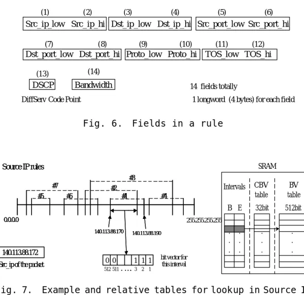
(19) Deficit Round Robin because of the flexibility in adjusting the priority between different flows and its long-term fairness.. 3.4.1 Classifier. Fig. 6 shows the format of a rule used by the classifier. Each pair of fields grouped in a rectangle represents the range of a specific dimension. The TOS field can also be seen as the DSCP field if the incoming packet is from another DiffServ domain. The policer uses Bandwidth to police EF traffic. The concept of the Multi-Dimensional Range Matching used to implement the classifier is described below. The r ules in a dimension form intervals, which may be overlapped by multiple rules. Each interval is associated with a BV (Bit Vector, which is 512-bit in our implementation and is stored in SRAM), which keeps track of the rules overlapped in this interval. Fig. 7 illustrates an example of the matching process in the source ip dimension.. 14.
(20) (1). (2). (3). (4). (5). (6). Src_ip_low Src_ip_hi Dst_ip_low Dst_ip_hi Src_port_low Src_port_hi (7). (8). (9). (10). (11). (12). Dst_port_low Dst_port_hi Proto_low Proto_hi TOS_low TOS_hi (13). (14). DSCP. Bandwidth. 14 fields totally. DiffServ Code Point. 1 longword (4 bytes) for each field. Fig. 6.. Fields in a rule. SRAM. Source IP rules #3 #7 #5. #2 #6. #1. CBV table. BV table. B E. 32bit. 512bit. . . .. . . .. #4. 0.0.0.0. 255.255.255.255 140.113.88.170. 140.113.88.190. 140.113.88.172 Src_ip of the packet. Fig. 7.. Intervals. 0 0 512 511. 1 1 1 . . . ... 3. 2. . . .. . . .. bit vector for this interval. 1. Example and relative tables for lookup in Source IP dimension. Upon the arrival of a packet, the classifier searches the interval table of each dimension for a match with the corresponding field in the packet. Once an interval is found for a dimension, the classifier consults the BV table f or the corresponding BV. If all six fields of a packet match an interval in six dimensions, respectively, the classifier ANDs the BVs of the intervals, and the index of the first non-zero bit in the result vector is the index of the matched rule. An additional 32-bit CBV (Compact Bit Vector), also stored. 15.
(21) in SRAM, is associated with each interval in order to speed up the lookup process of the BV. The usage of CBV is described as follows. If the Nth bit in a CBV equals 0, it means that all bits in the range from [32(N-1)+1]th to 32Nth bit in the BV are 0. On the other hand, more than one bit in the BV equal 1 in that range if the Nth bit of CBV equals 1. Because each bit in CBV containing 32-bit information in BV, the CBV can detect and avoid the unnecessary. memory. accesses and computations in ANDing the BV’s. Note that since AND and SRAM operations are longword-based in microengines, a BV is stored in the memory as 32-bit words. Because the SRAM in our hardware platform is only 2Mbyte, the maximum number of rules must be limited to 1024 (6 dimensions*2049*1024/8 > 2Mbytes, since there will be 2049 intervals in the worst case of 1024 rules, and 1024 bit of BV for each interval). We set it to 512 rules in our implementation for simplicity, in addition to other space overhead such as routing table and queues. After classifier returns the index of the matched rule, the policer and marker use the information contained in the rule to do the further processing (as described in Fig. 8). Each. rule. is. associated. with. additional. two. fields,. last_arrival_time and token, which are used in maintaining per-flow Leaky Bucket.. Policing and Marking: 16.
(22) If(rule[index].dscp = EF) token=(time_now-rule[index].last_arrival_time)*rule[in dex].bw+rule[index].token If(len_of_packet <= token) rule[index].token = token – len; // restore the rest of the tokens Else packet_discard(); TOS_of_packet = rule[index].dscp; // marked with DSCP in the packet header ElseIf(index = BE) enqueue(BE); Else enqueue(rule[index].dscp); Fig. 8.. Code of Policer and Marker. A timer is implemented by StrongARM to obtain the timing information. The last_arrival_time means the arrival time of the previous packet, and the token indicates the number of tokens left in the processing of last packet that matches this rule and available to the next one. Therefore, the total tokens available to the incoming packet can be computed and we can decide whether to admit it or not.. 3.4.2 Scheduler. 17.
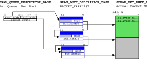
(23) Fig. 9 illustrates the design of the s cheduler using DRR. The ratio of quantum sizes between two adjacent classes is 2 in our implementation. To prevent from longer queuing delay and higher drop rate, the capacity of each queue is set to 32 the same as the quantum size of EF. The quantum of EF could be wasted if the queue size is smaller than 32, and the packets are also more likely to be dropped. Each packet is represented in a form of buffer descriptor when it is queued in SRAM, as shown in Fig. 10. The IXP1200 implements an SRAM free_list, which can be called for a memory block to store the buffer descriptor. The real packet is stored in SDRAM, and once it is scheduled for. transfer, the. transmitter thread uses the address of buffer descriptor and buffer handle in the descriptor to locate the packet. The former is used to map the start address of the real packet (buf_des_addr*64) in SDRAM, and the later is used to obtain the number of valid bytes in EOP (End Of Packet).. 32 descriptors. Enqueue. EF AF1 AF2 AF3 AF4 BE. TFIFO. Quantum ratio between all classes. Fig. 9.. EF : AF1 : AF2 : AF3 : AF4 : BE = 32 : 16 : 8. : 4. : 2. : 1. Scheduler using DRR. 18.
(24) SRAM_QUEUE_DESCRIPTOR_BASE Per Queue, Per Port. SRAM_BUFF_DESCRIPTOR_BASE PACKET_FREELIST. SDRAM_PKT_BUFF_BASE Actual Packet Storage Addr B. 31. 16 15. 87. 32. 0. Head Addr Tail Addr Packet Count. 0. 32. Next buf_handle. 32. 0. 64 bytes MP 64 bytes MP. 0 Next buf_handle. 32. 0 Next buf_handle. Fig. 10.. Packets in a queue. Chapter 4. External Benchmark and Design Pitfalls There. are. works. [13,14,15,16]. describing. DiffServ. performance evaluation. However, most of them are conducted through simulations. In this chapter, we investigate two important issues for a DiffServ edge device, functionality and. scalability,. through. hardware. benchmark.. For. functionality, w e evaluate the PHB of different flows and the 19.
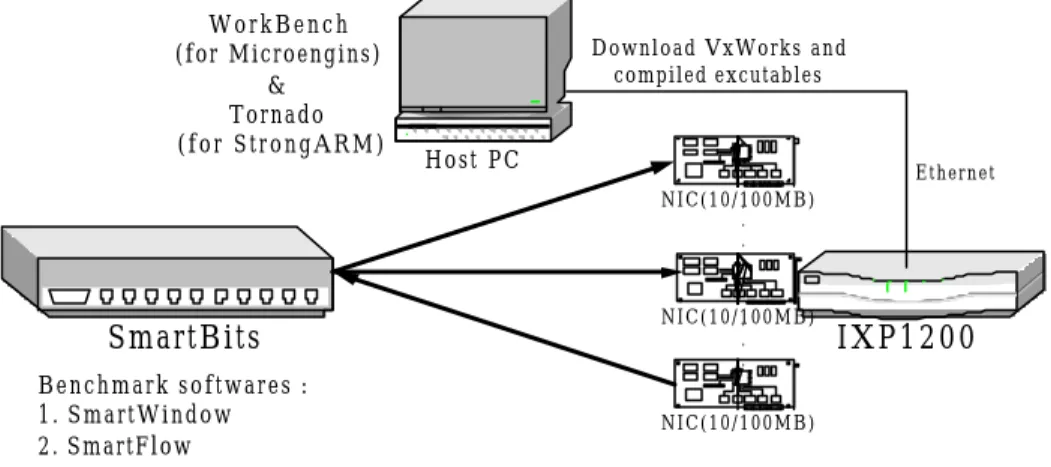
(25) fairness among input ports. For scalability, we want to know the aggregated throughput and how many flows our system can support while conforming their PHBs. Last, we identify a possible design pitfall named the MAC buffer problem and propose solutions for it. Another two versions of DiffServ are also implemented for comparison with the one of Range Matching, the Linear Search classifier in IXP1200 and the Linux-based Range Matching DiffServ whose CPU is Pentium III 800 and RAM is 128MB.. 4.1. Benchmark Environment. Fig. 11 illustrates the benchmark environment [13]. The host PC is used to remotely control the initialization and activities of IXP1200. We first setup the connection from host PC to IXP1200 and the IXP1200 then automatically download the linked image of StrongARM and microcode executables with Tornado. A fter entering the debugging mode in WorkBench, we can run the DiffServ code continually or set break points.. 20.
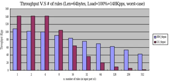
(26) WorkBench (for Microengins) & Tornado (for StrongARM). Download VxWorks and compiled excutables. Host PC. Ethernet N I C ( 1 0 / 1. 0 0 M B ) . .. N I C ( 1 0 / 1. 0 0 M B ). SmartBits. . .. Benchmark softwares : 1. SmartWindow 2. SmartFlow. Fig. 11.. 4.2. IXP1200. NIC(10/100MB). Benchmark environment. Functionality Test. Though the time complexity of Range Matching is O(n), the benchmark result in Fig. 12 shows a k*log n decrease in the throughput when the number of rules increases. This is because when the number of rules is small (as in our experiment), the coefficient k, which represents the effect from binary searches of multiple dimensions, dominates the classification process. As for linear search, we can see that the throughput is linearly decreased as the number of rules increases.. 21.
(27) Throughput V.S # of rules (Len=64bytes, Load=100%=148Kpps, worst-case) 160 140. Throughput (Kpps). 120 100 RM_thrput. 80. LS_thrput. 60 40 20 0 1. 2. 4. 8. 16. 32. 64. 128. 256. 512. n: number of rules (at input port x1). Fig. 12. Throughput and loss rate with varying number of rules Fig. 13 shows the throughput of the receiver threads of different allocations. Naturally, the throughput of two threads in two microengines is approximately two times of the one of a single thread. However, due to the lack of the computing. power,. the. throughput. of. four. threads. in. a. microengine is not four times of only one thread. In addition, the throughput of eight threads is not two times of the one of four threads. This is the result of memory contention. Not shown in Fig. 13 is the throughput, which is 20.5Mbps, of Linux-based Range Matching DiffServ when the number of rules is 512. It is almost same with the throughput of one thread in IXP1200, which means IXP1200 outperforms the general PC.. 22.
(28) 200. 1FE Rx on 1 ME. 180. 4FE Rx on 1 ME. Throughput (Mbps). 160. 2 FE Rx on 2 ME. 140. 8FE Rx on 2 ME. 120 100 80 60 40 20 0 1. 2. 4. 8. 16. 32. 64. 128. 256. 512. number of rules. Fig. 13. Aggregated throughput (Len=64bytes, worst case). Fig. 14 shows the relation between loss rate and packet length. When the packet length increases, the loss rate decreases. The reason is quite straightforward. At the same load condition, longer packets result in fewer packets for the classifier to process. One thing is interesting in this figure. No matter under what load condition, the loss rate of the flow, whose packet l ength is 512 bytes, is near 100%. Actually, this always happens to flows whose packet length is longer than a threshold. We call it the MAC buffer problem and will discuss it in the later section.. 23.
(29) 120. Loss Rate (%). 100. 80. 64byte 60. 128byte 256byte. 40. 512byte 20. 97. 93. 89. 85. 81. 77. 73. 69. 65. 61. 57. 53. 49. 45. 41. 37. 33. 29. 25. 21. 17. 9. 13. 5. 1. 0. Load (%) at input port x1. Fig. 14.. Loss rate with varying packet length (128-rules worst case). Fig. 15 shows the receive rate of four AF classes from four input ports, respectively. The traffic of AF4 begins to be dropped at load 25% because the output link is fully utilized so that the packets of low priority are more likely to be dropped. We can also observe from the figure that the service differentiation is strictly carried out in the 2:1 manner, as defined in our system, for two adjacent classes. We include the EF flow in our priority test in Fig. 16. Again, we see the AF3 flow that is of the lowest priority in this test begins to be dropped at load 25%. However, the other three flows continue to consume the bandwidth left by AF3 until the output queue of AF2 is full due to the growing traffic rate and its lower priority. While the other 3 AF flows obey the 2:1 traffic proportion, the EF flow reaches the steady state at 62,500pps set in the rule. It does not obey the 2:1. 24.
(30) proportion with other AF flows since the EF queue is not full yet. In the latency test in Fig. 17 corresponding to Fig. 16, we observe that the EF flow has a very low latency under all load conditions. Before load 25%, every flow has the same latency because the queues are not full. We also observe that the latency o f AF flows still obey the 2:1 proportion, which means. the. delay. in. output. queues. dominants. the. whole. end-to-end delay.. 120. AF1 AF2 AF3 AF4. 100. Receive rate (%). 80. 60. 40. 20. Load (%) at input port (x4). Fig. 15.. Priority test (Len=64bytes). 25. 97. 100. 94. 91. 88. 85. 82. 79. 76. 73. 70. 67. 64. 61. 58. 55. 52. 49. 46. 43. 40. 37. 34. 31. 28. 25. 22. 19. 16. 13. 7. 10. 4. 1. 0.
(31) 70000. EF. Receive throughput (pps). 60000. AF1 AF2. 50000. AF3 40000. 30000. 20000. 10000. 97. 100. 94. 91. 88. 85. 82. 79. 76. 73. 70. 67. 64. 61. 58. 55. 52. 49. 46. 43. 40. 37. 34. 31. 28. 25. 22. 19. 16. 13. 7. 10. 4. 1. 0. Load (%) at input port x4. Fig. 16.. Priority and bandwidth control test (Len=64byte, EF=62500pps). Fig. 18 shows the fairness among four input flows of the same class to one output link. The packet loss from load 25% to 42% is due to the fullness of the output link and is e ven between the four flows. After load 42%, we see an acute changing of loss rate among flows. This is because the unstableness of the receivers. The traffic load is too heavy in each input port so that the classification cannot be finished in time.. 120. AF1 AF2. 100. AF3 AF4. Receive rate (%). 80. 60. 40. 20. 100. 97. 94. 91. 88. 85. 82. 79. 76. 73. 70. 67. 64. 61. 58. 55. 52. 49. 46. 43. 40. 37. 34. 31. 28. 25. 22. 19. 16. 13. 10. 7. 4. 1. 0. Load (%) at input port (x4). Fig. 17.. 4(EF, AF1-3) to 1 latency test (Len=64bytes, 26.
(32) EF=62500pps). 70000. EF. Receive throughput (pps). 60000. AF1 AF2. 50000. AF3 40000. 30000. 20000. 10000. 91. 88. 85. 82. 79. 76. 73. 70. 67. 64. 61. 58. 55. 52. 49. 46. 43. 40. 37. 34. 31. 28. 25. 22. 19. 16. 13. 7. 10. 4. 1. 0. Load (%) at input port x4. Fig. 18. Four-to-One fairness test (64rules, 4 Rx in one ME). Compared with the four. receiver threads in only one. microengine in Fig. 18, the four receiver threads are divided into two groups in two microengines, as shown in Fig. 1 9. It is very clear that the receivers are more stable than those in one microeigine, thanks to the additional computing power from the second microengine.. 120. 100. Average 1->5 2->5 3->5 4->5. Loss (%). 80. 60. 40. 20. 100. 97. 94. 91. 88. 85. 82. 79. 76. 73. 70. 67. 64. 61. 58. 55. 52. 49. 46. 43. 40. 37. 34. 31. 28. 25. 22. 19. 16. 13. 7. 10. 4. 1. 0. Load (%) at input port (x4). Fig. 19.. Four-to-One fairness test(64rules, 2 Rx in ME0, 2Rx in ME1). 27.
(33) 4.3. Scalability Test. The test methodology is described below. We first measure the maximum load, which is 58% as shown in Fig. 20, for one flow that results in no packet loss. Then we want to know how well the system supports for a larger number of flows when the input load is below or above the load measured in Fig. 20. The bandwidth of each flow is set the same and the aggregated bandwidth is 50% of the link. The input load is evenly divided into 100 and 500 flows in the following two experiments, respectively.. 120. Average. Loss (%). 100. 1->5 2->5. 80. 3->5 4->5. 60. 40. 20. 97. 93. 89. 85. 81. 77. 73. 69. 65. 61. 57. 53. 49. 45. 41. 37. 33. 29. 25. 21. 17. 9. 13. 5. 1. 0. Load (%) at input port (x4). Fig. 20.. Single flow loss rate test. Fig. 21 shows the throughputs of 100-flows at three load conditions.. The. flows. strictly. follow. their. bandwidth. settings when the input load is 50%, which is below 58%, and become unstable when overloaded. However, most of the flows. 28.
(34) are limited to their bandwidth settings.. 800 700. Throughput (pps). 600 500 400 300. 50%. 200. 80% 100. 100% 97. 100. 94. 91. 88. 85. 82. 79. 76. 73. 70. 67. 64. 61. 58. 55. 52. 49. 46. 43. 40. 37. 34. 31. 28. 25. 22. 19. 16. 13. 7. 10. 4. 1. 0. Flow index. Fig. 21. Scalability test (Len=64bytes, 100flows, BW=74400/100=744 frame/sec, normal case). Fig. 22 shows the test of 500-flows as an extension of Fig. 21. To compare the results in these two figures, we define Average Performance Dropdown ( APD) of the flows at different loads as N. APD = 1 −. Ti. ∑ BW i =1. N. ,. where Ti is the throughput of flow i, N is the number of flows and BW is the bandwidth o f each flow set in this experiment. The APD’s of load 80% and 100% are 0.022 and 0.09 in 100-flows test, whereas 0.047 and 0.15, which are larger, in 500-flows test. This is due to the extra memory accesses required in binary search in 500-flows test. Besides, the flows in Fig. 22 still. strictly follow their bandwidth. 29.
(35) settings when the input load is 50%.. 200 180 160. Throughput (pps). 140 120 100 80 60. 50%. 40. 80%. 20. 100%. 491. 477. 463. 449. 435. 421. 407. 393. 379. 365. 351. 337. 323. 309. 295. 281. 267. 253. 239. 225. 211. 197. 183. 169. 155. 141. 127. 99. 113. 85. 71. 57. 43. 29. 1. 15. 0. Flow index. Fig. 22.. 4.4. Scalability test (Len=64bytes, 500 flows, BW=74400/500=148pps, normal case). MAC buffer problem. This section discusses the MAC buffer problem introduced in Fig. 14. An interesting thing is observed in Fig. 23. When the classifier is implemented with Linear Search, the system loses all the packets of length 512-byte under all load conditions. There are two causes to this situation, the slow classification. and. the. small. buffer. size,. which. are. illustrated below. Fig. 24 shows a diagram of packets reception. As described in section 3.3, the rest of MPs are transferred from MAC buffer, RFIFO to SDRAM after the SOP is classified. However, if SOP cannot be processed in time and the buffer is not large enough, the incoming MPs of the same packet could fill up the whole 30.
(36) buffer and thus result in a packet drop, and then 100% packet loss.. 120. Packet Loss rate (%). 100. 80. 64_byte 128_byte. 60. 192_byte 224_byte. 40. 256_byte 512_byte. 20. 97. 100. 94. 91. 88. 85. 82. 79. 76. 73. 70. 67. 64. 61. 58. 55. 52. 49. 46. 43. 40. 37. 34. 31. 28. 25. 22. 19. 16. 13. 7. 10. 4. 1. 0. Load(%) at input port (x1). Fig. 23. Packet loss of different packet lengths in Linear Search. RFIFO (64bytes). MAC buffer. SOP. SDRAM. MP&EOP. Classification process Receiver. Fig. 24.. Receiving process of a packet. Packet Length (byte). Table 2.. Rule matched. Loss. 1. 304. 3 1 th. normal. 2. 305. 3 1 th. 100%. 3. Any. 3 0 th. normal. Experiment results of Linear Search classifier for MAC buffer problem. 31.
(37) Since both the slow classification and small buffer contribute to the MAC buffer problem, two things are therefore interested, the maximum tolerable processing time of the classification and the maximum buffer size, which both help avoid this problem. The first question can be answered in table 2. From result 2 and 3 we can learn that, when a packet matches 30th rule, the classification is fast enough so that the receiver can move all MPs into SDRAM in time. That is, the maximum tolerable processing time (from classification to packet store in Fig. 4) for a SOP is about 120 SRAM accesses and 950 instructions, or 4550 cycles totally. We also find from result 1 and 2 that, the threshold of the packet length in MAC buffer problem is 304 bytes, and the size of MAC buffer is therefore 240 bytes (304 bytes - 64 bytes of RFIFO), which is different from 256 bytes mentioned in the specification of IXP1200. Another solution to MAC buffer problem is to enlarge the MAC buffer size to 1454 bytes (1518 bytes - 64 bytes of RFIFO), whose sum with RFIFO is the maximum packet size in Ethernet. Since there can be at least one packet in the MAC buffer and RFIFO, the problem can be avoided. Third, since the incoming MPs could fill up the whole buffer before SOP is classified, we just move the MPs into SDRAM before classification. Though the average delay may become longer due to the postponement of the classification and enqueue, 32.
(38) it won’t have critical impact on the system compared with the dominant output queuing delay. As to the Fig. 14, it is strange to see that the loss rates under MAC buffer problem are not 100%, which are different from the ones in Fig. 23. The reason is quite interesting. The receiving thread is not fast enough to avoid the MAC buffer problem in this experiment. However, the thread might sometimes get extra computing power for classification process thanks to context switching.. Chapter 5. Internal Benchmark and Bottleneck Discussions In this chapter we will have simulations for two DiffServs whose classifiers are implemented with Linear Search and Range Matching, respectively. Our goal is to see what cannot be seen in the external benchmarks, for example, the utilizations of microengines, SRAM and SDRAM, and try to find out the performance. bottlenecks. from. above. observations.. Some. solutions will also be proposed to solve those bottlenecks.. 5.1. Simulation Model. 33.
(39) Fig. 25 illustrates the simulation model. The HAL (Hardware Abstraction Layer) is used as an interface of StrongARM to IXP1200 hardware and Transactor. The Transactor, which is a simulator in the development tool called WorkBnech, instructs the virtual devices with the StrongARM and microengine executables. There are seven 100Mb input ports and one giga port for output. The input traffic in each port is configured as wire-speed. Host PC Foreign Model. StrongARM App HAL. Tornado. .dll file. IXP1200. Transactor Transactor IO. 1. Input Port: 0-6 2. Wire -speed input traffic. Fig. 25.. virtual devices SRAM. SDRAM. MEs. IX bus. Software simulation model. We simulate DiffServ in two algorithms, Linear Search and Range Matching, a nd try to find the performance bottlenecks of IXP1200. The number of rules is 64 in both cases.. 5.2. Simulation Result—Linear Search. Fig. 26 shows the performance statistics of the functional units. We see that SDRAM utilization is very low. This is because packet forwarding, which is the major consumer of. 34.
(40) SDRAM, is not critical in DiffServ.. Fig. 26.. Summary of performance statistics. Executing Microengine 0 Rec 10/100, 0 Rec 10/100, 1 Rec 10/100, 2 Rec 10/100, 3 Microengine 1 Rec 10/100, 4 Rec 10/100, 5 Rec 10/100, 6 Rec 10/100, 7 Microengine4 Xmit Sched Xmit 10/100, 1 Xmit 10/100, 2 Xmit 10/100, 3. Fig. 27.. Aborted. 61.7% 15.5% 15.4% 15.4% 15.4% 72.2% 15.3% 15.2% 15.1% 26.7% 68.5% 22.4% 14.6% 14.9% 16.5%. 18.1% 4.6% 4.4% 4.5% 4.5% 18.8% 4.3% 3.9% 4.3% 6.2% 27.4% 15.6% 3.8% 3.8% 4.1%. Stalled 0.1% 0.1% 0.1% 0.1% 0.1% 0.2% 0.1% 0.1% 0.1% 0.0% 0.0% 0.0% 0.0% 0.0% 0.0%. Idle 20.1%. 0.2%. 4.1%. microengine statistics of Linear Search DiffServ. From section 3.4.1 we know that the computing power of receiving threads and SRAM accesses are two important factors that affect the performance of the classifier. How ever, we can see from Fig. 26 and Fig. 27 that both receiver microengines and SRAM are not fully utilized while the actual throughput of the system is not wire-speed. The reason can be answered in the execution history in Fig. 28. There are four stages in a SRAM access, which are also shown in the figure and illustrated below. First, the request 35.
(41) is queued in one of the three command queues waiting for other SRAM accesses to complete. After a period of time the request is in the head of the queue and then removed from queue waiting to be scheduled. Third, when scheduled, the request is processed and a processing done is issued as the access completes. Finally, the thread that issues the request is signaled of the completion.. Fig. 28.. Execution history of Linear-Search classifier. The reason of low utilization of receiver microengines is that the SRAM accesses in Linear Search classifier are bursty, which can be seen in the execution history of Fig.28. Sometimes all the threads in a microengine wait for their SRAM accesses and thus cause an idle microengine. The vertical lines are added over the processing done. 36.
(42) points of some SRAM accesses in Fig. 28. The small gap between two lines means the actual SRAM access time, which is shorter than waiting time, and implicates the low SRAM utilization. Three methods can be proposed to solve the SRAM bottleneck that leads to the low utilization of receiver microengines. First is to divide one large SRAM into many smaller modules of the same address space. This could shorten the queuing delay of requests in the command queue if the requested addresses are in different memory modules. Second, we may adopt a new memory architecture, for example, RAMBUS DRAM (RDRAM) [17] in IQ2000 [18] that has a peak bandwidth of up to 1.6GBps which is two to three times of what SRAM supports. However, it may need a new interface between the memory and other functional units. Third, an additional cache can be used to reduce the number of memory accesses because the traffic in the same time period usually shows locality either in classification or in routing table lookup.. 5.3. Simulation Result—Range Matching. Not shown in Fig. 29 is the utilization of SDRAM and SRAM, which are 13% and 35.3%, respectively. The same explanation in section 5.1 can be applied to the low utilization of t hese two functional units. However, the two receiver microengines are nearly fully utilized in this simulation. Since both SRAM. 37.
(43) accesses. and. computing. power. are. critical. to. the. classification process, we can identify that the later is a performance bottleneck in the Range Matching DiffServ.. Microengine 0 Rec 10/100, 0 Rec 10/100, 1 Rec 10/100, 2 Rec 10/100, 3 Microengine 1 Rec 10/100, 4 Rec 10/100, 5 Rec 10/100, 6 Rec 10/100, 7 Microengine4 Xmit Sched Xmit 10/100, 1 Xmit 10/100, 2 Xmit 10/100, 3. Executing. Aborted. Stalled. Idle. 80.4% 20.1% 20.1% 20.1% 20.1% 80.4% 22.7% 22.7% 22.7% 12.3% 68.3% 23.1% 14.1% 14.8% 16.3%. 18.9% 4.7% 4.7% 4.7% 4.7% 19.2% 5.4% 5.4% 5.4% 3.1% 27.8% 16.3% 3.6% 3.8% 4.1%. 0.4% 0.1% 0.1% 0.1% 0.1% 0.2% 0.1% 0.1% 0.1% 0.0% 0.0% 0.0% 0.0% 0.0% 0.0%. 0.3%. 0.2%. 4.0%. Fig. 29. Microengine statistics of Range Matching classifier. Fig. 30 and Fig. 31 confirm our identification. From Fig. 30 we can see that most of the receiving threads spend all their time (not computing power) waiting for the completion of SRAM accesses, while the threads of Range Matching do utilize their computing power in Fig. 31.. 38.
(44) Fig. 30. The execution history of Linear Search in macro view. Thread executing. Fig. 31. The execution history of Range Matching in macro view. 5.4. Simulation Result—Execution Coverage. Fig. 32 and 33 shows the execution coverage of two implementations. The X-axis represents the index of the. 39.
(45) instruction in Microcode and the Y-axis represents the execution times of the instruction. It is very easy to see that, when processing the same amount of packets (70 packets in our simulation), Linear Search takes three times of execution times of Range Matching. The ratio could be larger if the number of rules increases.. Classification ME0 ME1. Polling. ME4. Fig. 32.. Execution coverage of Linear Search DiffServ. Classification ME0 ME1. Polling. ME4. Fig. 33.. Execution coverage of Range Matching DiffServ. 40.
(46) Chapter 6.. Conclusions. In this work, we first explain the need of network processors for today’s complex applications, and introduce the architecture and packet flow in IXP1200. Then we detail the mapping of DiffServ onto IXP1200. There are two most important modules in DiffServ, classifier and scheduler, which are implemented with Multi-Dimensional Range Matching and Deficit Round Robin. Finally we have external and internal benchmarks. in. order. to. find. the. bottlenecks. in. our. implementation and possible design pitfalls of IXP1200. The external benchmarks have shown that our implementation. 41.
(47) can support well the PHBs in DiffServ, and 500 flows at the input load of 58%. However, from the four-to-one test we see that the classifier is the performance bottleneck. The internal benchmarks prove this observation and identify that SRAM. and. microengines. are. the. bottlenecks. inside. the. classifiers of Linear Search and Range Matching, respectively. However, the classifier of Range Matching could still suffer from the SRAM bottleneck after the computing power of microengines is speeded up because of its heavy memory accesses. Together with the SDRAM bottleneck in IP forwarding, we can observe that the bottlenecks may shift from one functional unit to another depending on the specific service. Another interesting thing is shown in simulation that the bottleneck of SRAM does not necessarily occur at 100% utilization, it could even occur at 55% when the traffic is bursty. We also identify the MAC buffer problem and propose three solutions to attack the two necessary conditions, slow classification and small buffer. We show that the maximum classification time is 4550 cycles. Besides, the experiment result shows the buffer size is 240 bytes that is different from the one in the specification of IXP1200. Table 3 compares Linear Search and Range Matching adopted in our system. The time complexity of Range Matching is O(log n) when the number of rules is small as the ones in our experiment, and O(n) otherwise. The Control Store usage means 42.
(48) the number of instructions used to implement the receiver thread. The programmer should be aware of the 1K limit of the Control Store.. Time Space Bottleneck MAC Control Complexity Complexity buffer Store problem usage of Rx O(n) O(n) SRAM Yes 980. Linear Search Range S:O(log n) Matching M: O(n). O( n 2 ). microengine (SRAM). Yes. 1010. Table 3. Comparisons between Linear Search and Range Matching. References: [1]. NetScreen. Appliances,. http://www.netscreen.com/international/products/ appliances.html#ns5. [2] Intel. NetStructure. VPN. Gateway. Family,. http://www.intel.com/network/idc/ products/vpn_gateway.htm. [3] Intel Layer 3 Switching, “High speed LAN routing in an affordable. switching. solution”,. http://www.intel.com/network/tech_brief/layer_3_switch ing.htm. [4] eQoS Solutions for Service Providers using Riverstone Networks'. Switch. 43. Routers,.
(49) http://www.riverstonenet.com/technology/eqos.shtml. [5] Technical report on Hardware-Based Layer5 load balancer, http://www.nwfusion.com/research/2000/0501feat2.html. [6] Intel. Electronic. Design. Kit,. http://developer.intel.com/design/ edk/product/ixp1200_edk.htm. [7] Tammo, S., Scott, K., Larry, P., “Evaluating Network Processors in IP Forwarding”, Technical Report TR-626-00, Computer Science, University of Princeton, Nov 1999. [8] WindRiver, http://www.windriver.com/. [9] Development Tools User’s Guide, a document in the IXP1200 development tools CD. [10] Z.,. Blake, S., Black, D., Carlson, M., Davies, E., Wang, Weiss,. W.,. “An. Architecture. for. Differentiated. Services”, RFC 2475, Dec 1998. [11]. Lakshinan,. Policy-based. T.V.,. Stiliadis,. D.,. Packet. Forwarding. Using. “High-Speed Efficient. Multi-dimensional Range Matching”, ACM SIGCOMM’98. [12]. Shreedhar, M., George, V., “Efficient Fair Queuing. Using Deficit Round-Robin”, IEEE/ACM Transactions on Networking, June 1996, vol. 4, no. 3, pp. 375-385. [13] Nguyen, L.V., Eyers, T., Chicharo, J.F., “Differentiated Service Performance Analysis”, Fifth IEEE Symposium on Computers and Communications, 2000, pp. 328 –333. [14] Muppala, J.K., Bancherdvanich, T., Tyagi, A., “VoIP Performance on Differentiated Services Enabled Network”, 44.
(50) IEEE International Conference on Network, 2000, pp. 419 –423. [15] Harju, J., Kivimaki, P., “Co-operation and Comparison of Diffserv and Intserv: performance measurements”, 25th Annual IEEE Conference on Local Computer Networks, 2000, pp. 177 –186. [16] Di, Z., Mouftah, H.T., “Performance Evaluation of Per-Hop Forwarding Behaviors in the DiffServ Internet”, Fifth IEEE Symposium on Computers and Communications, 2000, pp. 334-339. [17]. Data. Sheets. of. RDRAM,. http://www.rambus.com/developer/support_rdram. html [18]. IQ2000. Network. Processor,. VITESSE. http://www.vitesse.com/products/ categories.cfm?family_id=5&category_id=16. 45. Corp,.
(51)
數據
+7

相關文件
Therefore, it is our policy that no Managers/staff shall solicit or accept gifts, money or any other form of advantages in their course of duty respectively without the
In this paper, we illustrate a new concept regarding unitary elements defined on Lorentz cone, and establish some basic properties under the so-called unitary transformation associ-
It clarifies that Upāyakauśalya, in the process of translation, has been accepted in Confucian culture, and is an important practice of wisdom in Mahāyāna Buddhism which
SG is simple and effective, but sometimes not robust (e.g., selecting the learning rate may be difficult) Is it possible to consider other methods.. In this work, we investigate
Since huge quantities of transactions are involved in daily operations of a hotel, the accounting department always has to deal with complicated calculations which undoubtedly
To look at the most appropriate ways in which we should communicate with a person who has Autism and make it.. applicable into our day to
The aim of this study is to investigate students in learning in inequalities with one unknown, as well as to collect corresponding strategies and errors in problem solving..
The purposes of this series studies were to investigate difference between batting performance at peak level and slump level in visual cue strategy, dynamic
