Thermodielectric effect in dual-frequency cholesteric liquid crystals
Yu-Cheng Hsiao and Wei Lee*
Institute of Imaging and Biomedical Photonics, College of Photonics, National Chiao Tung
University, Guiren Dist., Tainan 71150, Taiwan
ABSTRACT
Thermodielectric effect in dual-frequency cholesteric liquid crystals (DFCLCs) is an important issue and has rarely been studied in the past. DFCLC materials have many applications such as fast-switching CLCs, light modulators, and tunable photonic devices. However, DFCLCs characteristically need high operation voltage, which hinders their further development in thin-film-transistor operation. Here we present a lower-voltage switching method based on thermodielectric effect. Dielectric heating effect entails applying an electromagnetic wave to occasion dielectric oscillation heating so to induce the increase in crossover frequency. The subsequent change in dielectric anisotropy of the DFCLC permits the switching, with a lower voltage, from the planar state to the focal conic or homeotropic state. Furthermore, we also demonstrate the local deformation of the CLC helical structure achieved by means of the thermodielectric effect. The wavelength of the deformation-induced defect mode can be tuned upon varying the dielectric heating power. The physics and the calculation of dielectric heating in DFCLCs are described.
Keywords: cholesteric liquid crystals, dual-frequency liquid crystal, dielectric heating effect, optical stability, photonic
devices
1. INTRODUCTION
Dual-frequency nematic liquid crystal (DFNLC) was first developed in the 1970s and 1980s.1 DFLCs are a LC mixture
whose dielectric constant parallel to the molecular axis, ε||, highly depends on the frequency; and the dielectric constant
perpendicular to the molecular axis, ε⊥, is independent of frequency within the range of tenth of MHz. In other words,
dielectric anisotropy of DFNLC is positive in mid-frequency and negative in radio-frequency regions. The specific frequency where dielectric anisotropy cross zero is known as crossover frequency (fc). Based on this feature, DFNLCs
have been suggested to extensive applications such as fast-switching optical devices,2,3 tunable lens,4 optical retarders,5
stable system,6,7 and so forth. In addition, dual-frequency cholesteric liquid crystals (DFCLCs), mixtures that made of
DFNLCs and chiral dopants, have a great potential for photonic applications. DFCLCs hold the same frequency-dependent-dielectric-anisotropic characteristic as DFNLCs do which allows DFCLCs can be fast switched among multiple of their peculiar states. Typically, switching CLCs from transparent planar (P) state to opaque focal conic (FC) state relies an AC voltage pulse. The reverse transition, from the FC to P state, however, cannot be directly switched to without an intermediate state. Our previous studies have demonstrated the direct two-way switching between P and FC states with DFCLCs, characterizing a much shorter transition time for practical applications such as light shutters8,9 and
fast-switching color-reflective displays.10 Nevertheless, DFCLC devices still suffer from two common problems—high
operation voltage and thermodielectric effect. In this work, we explore the physics of thermodielectric of a DFCLC system and exploit such effect to switch the states of DFCLCs without necessitating high voltage. Furthermore, through thermodielectric effect a local deformation in the CLC helical structure can be created, serves as a photonic defect layer. The wavelength of the deformation-induced defect modes are tunable by simply applying a frequency-modulated voltage which yields different dielectric heating power.
*[email protected]; phone +886 (0)6 303-2121; fax +886 (0)6 303-2535
Liquid Crystals XIX, edited by Iam Choon Khoo, Proc. of SPIE Vol. 9565, 95651D © 2015 SPIE · CCC code: 0277-786X/15/$18 · doi: 10.1117/12.2188883
Proc. of SPIE Vol. 9565 95651D-1
The DFNLC 25 °C. The ch DFCLCs wer mm-thick ind rubbed plana thermodielect order to avoid cells and the with a digital dependent co E4980A),usi transmission experimental is applied acr denote the re the electric fi the electric fi field when th efficiency of LC molecula thermodielect 3.1 The the Figure 2 sho frequency ran vertical and p material used hiral dopant w re injected in dium–tin-oxid ar alignment tric effect in d the temperat hot plate to s l thermometer omplex dielect ing a 0.5 Vrm spectra of th data were me ross a DFCLC lative permitt eld, respectiv ield direction. he DFCLC is i absorption of ar dipoles, w tric effect in D Figure 1 eory of therm
ows the measu nge from 1 k parallel dielec d in this study was S-811 (M isotropic pha de glass substr layers produ DFCLCs, the ture gradient stabilize the s r whose therm tric function ε ms sinusoidal he DFCLC c easured at an C cells, it imp tivity compon ely. When a lo In contrast, Δ in a high-frequ f electromagne which is sig DFCLCs is dis . Schematic illu modielectric ef ured real (ε′) kHz to 1 MHz ctric constant 2. E was MLC-20 Merck), which w
ase to the cells rates coated w uce an unifor e ambient tem in the DFCLC surrounding ai mocouple was ε′ – iε″ was a probe voltage ells were acq ambient temp poses a torqu nents in the ca ow-frequency Δε becomes ne uency (> fc) fi etic wave. Th gnificant at p scussed. ustration of the 3. RESUL ffect in DFCL and imagina z. Note that t components c XPERIMEN 048 (Merck) w was mixed in s by capillary with planar al rm single-dom mperature T0 w C cells, we ins ir at 300 K. T s attached to t acquired with e, which was quired with a perature of 299 ue on the LC ases of the dire y (< fc) field is
egative and th ield. The stren e dielectric he particular fre DFCLCs appli LTS AND DI LCs ary (ε″) parts the bias volta corresponding
NTAL
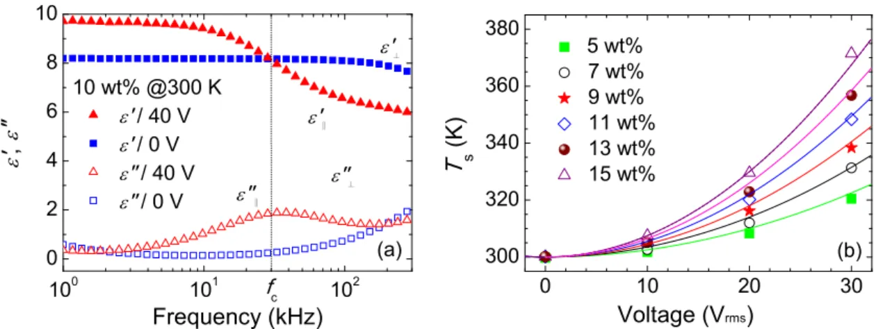
with the clearin n the DFNLC y action. Each lignment laye main texture was fixed at serted a pair o The temperatu the outer surfa a computer c s lower than a spectrophoto 9 ± 1 K. Whe director, depe ector parallel s applied, Δε > he LC director ngth of the the eating effect i equencies ran cation based on ISCUSSION of the dielec ages, 0 and 40 g to ε⊥ and ε∥ ng point at 11 host at concen DFCLC cell rs, the cell ga to the initial 300 K with a of ~1-mm-thic ure of the cell ace of the DF controlled pre the Fréederic ometer (Ocea en a frequency ending on Δε to the electric > 0 and the dir r tends to be p ermodielectric s manifested t nge.10 The t n thermodielect N ctric propertie 0 V, permitte ∥, respectively 0 °C and Δε = ntrations of 0– was compose ap was 11.6 ± l P state. To a temperature ck plastic strip l surface, Ts, w FCLC cells. T ecision LCR m cksz threshold an Optics HR y-modulated e = ε|| − ε⊥, wh c field and pe rector tends to perpendicular c effect is dete through reorie theory and c tric effect. es of a DFCL ed the measur y. We can obs = 2.8 at 1 kHz –15 wt%. The ed of two 1.1 ± 0.5 μm. The o analysis the controller. In ps between the was measured The frequency meter (Agilen d voltage.The R2000 +). Al electric field E here ε|| and ε⊥ erpendicular to o be parallel to to the electric ermined by the entation of the calculation o LC cell in the rements of the serve that fc is z, e -e e n e d -nt e ll E ⊥ o o c e e f e e s
Proc. of SPIE Vol. 9565 95651D-2
about 20 kHz main frequen ion charges; frequency ran the dielectric configuration thermodielect dielectric stor and where ε’(ω) a high-frequenc be determined The orientati with the time times about 1 much shorter of LC related permanent di is reorientatio time because director (as th the perpendic of pl. The re Typically, th dependence o where Ea is th A0 represents
flow rate Qout
z in the condi ncy ranges. Fir
here the ion nge between 1 spectra at fre n.14 However tric effect. Th rage as well a and ε”(ω) are cy dielectric c d from measu on polarizatio e scales rangin 10−4–10−2 s.13 r time scale co d to the orient pole moments on of pl contri of the smalle he axis of the cular compone elaxation time he dielectric h of fc satisfies th he activation e s a material co t at the interfa Figure 2. Sch itions of 10 w rstly, the low nic behavior i 1 and 100 kHz equencies abo r, the most he frequency s dielectric lo
e the real and constants of th urements. The on of LCs, as ng from 10−9 On the other ompared with tational polari s. There are fo ibuted to the p er moments o cone); when t ent of the diel e for the mod heating induc he Arrhenius energy of the onstant, kB sta ace of glass an hematic illustra wt% chiral dop frequency reg is dictated ba z is produced out 1 MHz are important is dependence ss, follows the * ε ( ε′ ε the imaginary he respective d e dielectric dis ssociated with to 10−2 s. The hand, electron LC reorientat ization. Consi four relaxation parallel compo of inertia invo the applied ele lectric polariza de d is thus ced LC flow equation c f = dielectric rela ands for Bolt nd air as well a Qo ation of orientat pant and at 30 gime (f < 1 kH ased on the e with the diele e associated b the dielectr of the compl e Debye-type *( )ω =ε ω'( )+
(
2 ( ) 1 s ε ε ω ω τ∞ − = +(
( ( ) 1 s ε ε ω ω∞ − ′′ = + y parts of the dispersion reg ssipation, whic h the reorienta e reorientation nic and molec tion; therefore ider such a LC n modes: mod onent of dielec olved. Mode c ectric field is p ation. Finally, significantly is in the Mo 0 B exp E A k ⎛ = ⎜− ⎝ axation corresp tzmann consta as cell surface out = hA (Ts −T tional relaxation 00 K. The freq Hz) demonstra electrode and ectric orientat by the pseudo-ric orientatio ex dielectric molecular rel ( ) i "ε ω + ,)
2 D ε τ∞ + ∞,)
D 2 2 D )ωτ ω τ∞ , Debye’s mod gion. The Debych generates h ation of perm n of dipoles c cular polariza e, we focus on C molecule w de a is rotation ctric polarizat c is associated perpendicular , mode d is a larger than t ode d. For a a B E T ⎞ ⎟ ⎠, ponding to th ant, and T is t
e and the surro
T0),
n modes for a m
quency spectr ates the induce
interface pol tion behavior -relaxation or on behavior constant of a laxation del. εs and ε∞ ye relaxation t heat in the LC manent electric covers the LC
tions are impo n the discussio with the longit
ns of pt around
tion. The mod d with conica r to the directi different mod the relaxation describe of e rotation alon the absolute t ounding air fo molecule in DFC ra can be divi ed polarization larizations.12 of LC molecu iginating from of LCs in a LC, which
are the low-(s
time τD = 1/ω C layer, follow c dipoles, is r reorientation ortant to be c on of the diele tudinal pl and
d the long axi de a has a sma al rotations of ion of LC and de related with n time of any DFCLCs, th ng the molecu temperature. N llows the equa
CLC medium.
ided into three n due to space Secondly, the
ules.13 Finally
m the ITO cel discussion o represents the
static) and the
D = 1/2πfD can ws from ε”(ω) relatively slow n characteristic onsidered in a ectric behavior d transversal p
is, and mode b aller relaxation fpl around the contributes to h the flip-flops y other mode e temperature
ular short axis Next, the hea ation e e e y, ll f e e n ). w c a r pt b n e o s e. e s, at
Proc. of SPIE Vol. 9565 95651D-3
100 101 102 0 2 4 6 8 10 ε'∥ ε''∥ ε'⊥ ε
'
, ε"
Frequency (kHz) 10 wt% @300 K ε' / 40 V ε' / 0 V ε'' / 40 V ε'' / 0 V fc ε''⊥ (a) 0 10 20 30 300 320 340 360 380T
s (K) Voltage (Vrms) 5 wt% 7 wt% 9 wt% 11 wt% 13 wt% 15 wt% (b)Figure 3. (a) Dielectric dispersion of a DFCLC sample consisting of 10 wt% of chiral dopant at 300 K as well as (b) dielectric heating temperature of DFCLC cells under different applied voltages.
where h is the heat transfer coefficient and is of ~40 Wm−2K−1 for the glass substrate15 and A is the heat-transfer area and
of 1 cm2 in this study. If we ignore the small temperature gradient in the DFCLC bulk, the average temperature T of the
DFCLC molecule in thermal equilibrium can be written as16
T − T0 = (1 + Bi) (Ts − T0),
where Biot number of the glass plate is about 0.04 and is the dimensionless, which is negligible to readily deduce T = Ts.
In this study, we used electric field, whose strength E = Vrms/d, for simplicity, that the electric field is homogeneous in
the cell. The dielectric heating power density P of the LC bulk is thus given by 2 2 0 rms 0 2 2 ( ) ( ) f V P E d π ε ε ω ω ε ε ω′′ ′′ = ⋅ ⋅ =
,
where ω represents the angular frequency and ε0 is the permittivity of free space. In this report, the pretilt angle (< 2°) is
small enough, so the imaginary part of the complex dielectric permittivity is roughly equal to ε ε0 ⊥′′ in the initial state. However, ε⊥′′ is a linear function of the chiral dopant concentration at 100 kHz based on the past report11
( )c c
ε⊥′′ = +α β
,
where α = 0.016 and β = 0.169 wt%−1 by fitting. In our experiment, ε
⊥′′ did not explicitly vary with T. Also note that c is lower than 16 wt%, beyond which the DFCLC cell became difficult to operate. Now that the LC layer is thin as compared with the glass plates, one can neglect the heat stored in the LC layer itself. As a result, the heat generation Qin
and dissipation Qout can be expressed as Qin = PdA = Qout. The equilibrium temperature of the LC to proceed to
(
) (
)
2 rms 2 0 0 rms 2 f 1 Bi A c V T T T f cV hd π α β γ + + = + ≈ +,
where both Bi and α, in comparison with 1 and βc, respectively, are ignored in the approximation. The relation 2
s 0 rms
T T T f cV
Δ = − ∝ is clearly confirmed by the experimental data as shown in Fig. 3. One can see that the dielectric heating effect is more drastic in the samples with higher CP concentrations as manifested by the higher temperatures measured. It is also clear from Fig. 3 that the experimental data are in good agreement with the simulated results predicted.
Proc. of SPIE Vol. 9565 95651D-4
3.2 Lower operation voltage in DFCLCs based on the thermodielectric effect
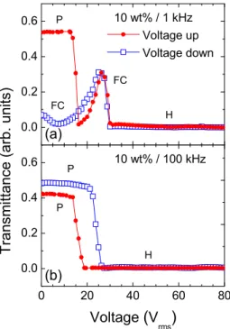
DFCLC devices are powerful and have potential to many applications as previous mentioned. However, all DFCLC devices suffer from one common problem—high operation voltage. We employ this thermodielectric effect to switch the cell from the P to the FC or H state by a lower operation voltage. Figure 4 illustrates the electro-optical properties of a DFCLC device (with 10 wt% chiral dopant) between crossed polarizers at low frequency 1 kHz and high frequency 100 kHz. When the low-frequency (1 kHz) voltage is applied, the DFCLC bulk shows positive Δε, and the device is initially at the P state. However, through a range of increasing operation voltages, the DFCLC cell exhibits the three main optical states. The colorful brightest one is the initial P state and the scattering FC state appears subsequently at ~13–30 Vrms.
Finally, the optical texture appears to be the H state when the applied voltage is over ~30 Vrms as demonstrated in Fig. 4(a). In the voltage ramp-down route, the optical texture changes from the H to FC state and, the device retains the FC state because of bistability. However, when the driving voltage operates at the high frequency (100 kHz), the DFCLC exhibits negative Δε. The high-frequency voltage causes severe dielectric heating effect and, in turn, the blue shift of crossover frequency fc, eventually inducing the positive dielectric torque. Consequently, the optical texture of the
DFCLCs transform from the P state to the FC or H state even when the applied voltage is as low as ~15 Vrms (Fig. 4(b)).
Based on this thermodielectric effect, the operation voltages required for switching the P state is lower compared with that in the convectional drive scheme. Figure 5 shows the images of real DFCLC cells of thermodielectric induce the molecular flowing under the cross polarizers. We can observe that the P state change to the H state slowly based on the thermodielectric effect. The thermo-induced crossover frequency shifting usually takes time and the optimized condition must be considered. The thermo-induced respond times, defined as the time interval between 10% and 90% of the
0 20 40 60 80 0.0 0.2 0.4 0.6 0.0 0.2 0.4 0.6 P Voltage
(
V rms)
10 wt% / 100 kHz H P P FC H 10 wt% / 1 kHz Voltage up Voltage down (b) Tran sm itta nc e (arb . u nits) (a) FCFigure 4. Voltage-dependent transmittance at operation frequencies of (a) 1 kHz and (b) 100 kHz. under crossed polarizers.
Proc. of SPIE Vol. 9565 95651D-5
Figure Table 1 minimum–ma frequency (sa increased tran 3.3 Thermo Photonic cry inhibited und interrupts the material as a defect modes have been dem PC; for exam the permanen also can be us in central DF When polariz chirality of D polarized ligh that the local experimental transmission first appeared
nm at 50 Vrm
doubt that the continuously the pitch leng calculated by Berreman ma of 1.375 μm i enhanced the middle (defe wavelength o e 5. Images of D . Transition tim Frequ (kH 5 10 15 aximum trans ay, 50 kHz) d nsition time be odielectric ge stals (PCs) h der the Bragg e periodicity o defect layer i s, many applic monstrated. C mple, infiltratio nt existence o sed as power CLCs layer as zed light pass DFCLCs will ht was reflecte l deformation transmittanc defect peak o d at the wavel ms because of e heating time applied for 3 gth, simulatio y using the co atrix. Howeve in the middle, e thermodiele ect) layer at a of the TIDM DFCLC cells of
mes from the pla thre ency Hz) 8 w 0 0 0 mittance diffe due to the wea ecause of the eneration of d have been ext condition, ge of the PC stru in the PC stru cations such a Conventionally on with liquid f the defect la to generation s gradient dist sed through a l induce ther ed within the n-induced chan ce spectra of originating fro ength of 640 n the higher he e was an impo 0 s. In order t ons results we ommercial sof er, by decreasi , one can see t ctric effect. T a resulting h
varied with t
f dielectric heati
anar to the hom ee different freq wt% 9 w 8300 307 7350 erence, are sh aker dielectric long time to s defect modes ensively stud enerating the s ucture, photon ucture, the def s optical filter y, the way to p crystals (LCs ayer. Howeve of defect mod tribution.22 a DFCLC con rmodielectro-i PBG owing t nge in pitch the DFCLC om the TIDL nm as the vol eating power ortant element to further insp ere performed ftware DIMO ing the pitch l that the simula The pitch wa high temperatu
the energy de
ing effect induc
meotropic state w quencies. (Adop Transitio wt% 10 5 780 283 5 640 owed in Table c heating effe shift fc to go b in a DFCLC died in the pa so-called phot n will confine
fect modes can
rs,20 low-thres produce defec s) in a multilay er, CLCs or D des in a DFCL ntaining a the induced defec to the left chir gave rise to a in various was observed ltage increased resulting in a t in the experim pect the intera d and are dep OS, which is b length from 4 ated data roug as, accordingl
ure, giving a ensity and the
ced the molecul
with various chi pted from Ref.
on time (ms) 0 wt% 1 1 420 250 1 350 e 1. The trans ct, and a high eyond the hig
as a “new” p ast.17,18 In a P tonic band ga in the defect n be generate shold lasers,21 ct modes is thr yer PC.3 Such DFCLCs are o LCs. Because ermodielectro ct mode (TID rality of S811 a TIDM wind heating cond d in the PBG d to 40 Vrms. T a shorter pitch ment. We mea action between picted in Fig. based on the 400 to 290 nm ghly resemble ly, shortened a blueshifted e defect-layer
lar flowing und
iral-dopant conc 11.) 1 wt% 1 8 560 286 7 530 sition time inc her applied fre gher frequency photonic devi PC structure, ap (PBG). Wh t layer.19,20 By ed in the PBG and fluoresce rough prefabri h defect mode one kind of PC of the dielectr -induced defe DM). It is cle and the DFC dow in the PB ditions are als
for the LCP The spectral p h length in the asured each sp n the TIDM a 6(b). The op extended 2 × m (as labeled in the experime and optical p TIDM. Figur r pitch based
der the cross pol
centrations at 1 12 wt% − 344 9210 creases for an equency (150 y. ice the propagati hen an artificia y inserting a t . Utilizing the ence enhancem ication of a de es are often pe Cs. Thermodi ric heating eff ect layer (TID
ear that the CLC to be left BG for the L so shown in
case. A prono peak then blue
e middle laye pectrum after and the local d ptical spectral × 2 Jones mat n the legend) ental spectra. A path length r re 7(a) illustr on previous larizers. 5 Vrms at applied lower 0 kHz) rise the ion of light is al defect layer third dielectric e properties o ment devices2 efect layer in a ersistent due to ielectric effec fect is induced DL), the same left circularly -handed. Note LCP light. The Fig. 6(a). A ounced TIDM eshifted to585 er. There is no a voltage was deformation o profiles were trix and 4 × 4 for a distance A high voltage educed in the rates how the equation. The r e s r c f 1 a o ct d e y e e A M 5 o s f e 4 e e e e e
Proc. of SPIE Vol. 9565 95651D-6
/
i
DO 620 Wavelengtl (a) sáo séo h (nm) N co coa a
al 01O o O N O
Energy density (J/pnl3) Transmittance ( %) 100 80 60 -40 20 o 400 501
W
(b) 7oo 800nm)
380 360 340t
° 320á
300 280 ir91 6f different spat configuration be understoo spectrum of DFCLC cell. mentioning th the main reas time is faster spectra. On th that TIDMs gradient chan minutes in DF Figure 6. (experime Ref. 22.) tial distributio ns. Since a sm d as a result a DFCLC un This result is hat the degree son to describ r to switch thhe contrary, u are difficult t nged over time
FCLCs. Howe
Transmission ental data) and
ons of the pi moother pitch d of the increm nder a prolon s qualitatively e of ideal defe be the propert he states, and under lower ap to demonstrat e before a sta ever, this prob
spectra of DF (b) compared t
itch were con distribution m ment in effec ged heating t y in good agre ect-mode prof ies of TIDMs then result in pplied voltage te or become te of thermal blem can be so FCLC with the o various pitch nsidered. The may be conside tive optical d time (50 Vrms eement with th file is affect b s. If the dielec n the smoothe e, the time of stabilized. S equilibrium w olved with the
rmodielectric i h values in the m e DFCLC wa ered as a struc defect thickne s for 50 s) fo he prediction by a number o ctric power of er pitch gradi
ideal one pea Since the ther was reached, t e polymer stab induced defect middle defect la s divided into cture with a th ess. Figure 7( or a smaller t by the simula of factors. Th f heating is hi ent generating ak mode is lon modielectric the TIDMs we bilization of D modes (a) at ayer in DFCLC o 10 layers w hicker defect b) depicts an temperature g ation results. I e thermo-hyd igher, the ther g the non-ide nger. It is wor effect induce ere only obser DFCLCs or CL
various applie Cs (simulated da
with the pitch layer, this can n experimenta gradient in the It is importan drodynamics is rmo-transition eal plural-peak rth mentioning d temperature rved for a few LCs.6,23 ed voltages ata). (After h n al e nt s n k g e w
Figure 7. (a) Wavelength of the TIDM varying with the energy density and simulated pitch of the middle defect layer. The symbols show the experimental (blue) and the simulated (red) results. (b) Experimental spectrum obtained in a specific pitch-deformation exhibiting two defect-mode peaks in the PBG.(Adopted from Ref. 22.)
Proc. of SPIE Vol. 9565 95651D-7
Based on the thermodielectric effect in DFCLCs, we have demonstrated that photonic defect modes can be induced and that the switching and tuning of them can be realized by local deformation of the pitch in the middle layer of a DFCLC cell. An external applied voltage at a high frequency across the DFCLC cell can supply the dielectric heat to induce a defect layer owing to the changed pitch susceptible to the gradient temperature in the DFCLC cell. The TIDMs appeared only when the incident circularly polarized light had the same handedness as the DFCLC. The tuning of the TIDMs can be performed by local compression of the defect-layer helix in DFCLCs, allowing the defect mode to blueshift. Based on controlling the extent of the modulation of the helix condition, a continuous shift of the TIDMs can be realized using the self-organizability of DFCLC without prefabrication of the artificial defect layer. On the basis of thermodielectric effect, various potential applications can be expected such as single-mode lasing, monochromatic selection, on-chip devices and optical communications.
4. CONCLUSION
In summary, the interesting properties of dielectric heating in DFCLCs have been investigated. In a high-frequency-modulated electric field, the thermodielectric effect leads to the increases in temperature resulting in upshift to crossover frequency. Once the sign of dielectric anisotropy is altered the optical states of DFCLCs are changed thereby. Numerous of possible applications were proposed based on this phenomenon, including fast optical modulators, fast shutters and displays. The DFCLCs can be switched from the P state to FC or H state with a low driving voltage at the expense of switching time. Thermodielectric effect can also generate photonic defect modes in a DFCLC. The induced photonic defect mode is tunable in wavelengths and the number of them is controllable. This intriguing effect is believed to have more possibilities than those are proposed in this paper.
ACKNOWLEDGMENTS
The authors are grateful for the financial support from the Ministry of Science and Technology, Taiwan under grant Nos. 101-2112-M-009-018-MY3 and 104-2112-M-009-008-MY3.
REFERENCES
[1] Schadt, Martin., “Liquid crystal materials and liquid crystal displays,” Annu. Rev. Mater. Sci. 27, 305–379 (1997).
[2] Golovin, A. B., Shiyanovskii, S. V. and Lavrentovich, O. D., “Fast switching dual-frequency liquid crystal optical retarder, driven by an amplitude and frequency modulated voltage,” Appl. Phys. Lett. 83, 3864–3866 (2003).
[3] Hsiao, Y.-C., Wu, C.-Y., Chen, C.-H., Zyryanov, V. Ya. and Lee, W., “Electro-optical device based on photonic structure with a dual-frequency cholesteric liquid crystal,” Opt. Lett. 36, 2632–2634 (2011).
[4] Pishnyak, O., Sato, S. and Lavrentovich, O. D., “Electrically tunable lens based on a dual-frequency nematic liquid crystal,” Appl. Opt. 45, 4576–4582 (2006).
[5] Golovin, Andrii B., Sergij V. Shiyanovskii and Lavrentovich O. D., “Fast switching dual-frequency liquid crystal optical retarder, driven by an amplitude and frequency modulated voltage,” Appl. Phys. Lett. 83, 3864– 3866 (2003).
[6] Hsiao, Y.-C., Hou, C.-T., Zyryanov, V. Ya. and Lee, W., “Multichannel photonic devices based on tristable polymer-stabilized cholesteric textures,” Opt. Express 19, 23952–23957 (2011).
[7] Hsiao, Y.-C., Zou, Y.-H., Timofeev, I. V., Zyryanov, V. Ya. and Lee, W., “Spectral modulation of a bistable liquid crystal photonic structure by the polarization effect,” Opt. Mater. Express 3, 821–828 (2013).
Proc. of SPIE Vol. 9565 95651D-8
[8] Hsiao, Y.-C., Tang, C.-Y. and Lee, W., “Fast-switching bistable cholesteric intensity modulator,” Opt. Express 19, 9744–9749 (2011).
[9] Hsiao, Y.-C. and Lee, W., “Fast-switching bistable light shutters based on dual-frequency cholesteric liquid crystals,” 16th Opto-Electronics and Communications Conference 95–96 (2011).
[10] Lin, F.-C. and Lee, W., “Color-reflective dual-frequency cholesteric liquid crystal displays and their drive schemes,” Appl. Phys. Express 4, 112201 (2011).
[11] Hsiao, Y.-C. and Lee, W., “Lower operation voltage in dual-frequency cholesteric liquid crystals based on the thermodielectric effect,” Opt. Express 21, 23927–23933 (2013).
[12] Liu, H.-H. and Lee, W., “Time-varying ionic properties of a liquid-crystal cell,” Appl. Phys. Lett. 97, 023510 (2010).
[13] Yin, Y., Shiyanovskii, S. V., Golovin, A. B. and Lavrentovich, O. D., “Dielectric torque and orientation dynamics of liquid crystals with dielectric dispersion,” Phys. Rev. Lett. 95, 087801 (2005).
[14] Tang, C.-Y., Huang, S.-M. and Lee, W., “Dielectric relaxation dynamics in a dual-frequency nematic liquid crystal doped with C.I. Acid Red 2,” Dyes Pig. 88, 1–6 (2011).
[15] Cengel, Y. A., Cimbala, J. M. and Turner, R. H., Fundamentals of Thermal-Fluid Sciences, 4th ed. (McGraw-Hill, 2011).
[16] Bergman, T. L., Lavine, A. S., Incropera, F. P. and DeWitt, D. P., Fundamentals of Heat and Mass Transfer, 7th ed. (Wiley, New York, 2011).
[17] Yablonovitch, E., “Inhibited spontaneous emission in solid-state physics and electronics,” Phys. Rev. Lett. 58, 2059–2062 (1987).
[18] John, S., “Strong localization of photons in certain disordered dielectric superlattices,” Phys. Rev. Lett. 58, 2486–2489 (1987).
[19] Yablonovitch, E., Gmitter, T. J., Meade, R. D., Rappe, A. M., Brommer, K. D. and Joannopoulos, J. D., “Donor and acceptor modes in photonic band structure,” Phys. Rev. Lett. 67, 3380–3383 (1991).
[20] Foresi, J. S., Villeneuve, P. R., Ferrera, J., Thoen, E. R., Steinmeyer, G., Fan, S., Joannopoulos, J. D., Kimerling, L. C., Smith, H. I. and Ippen, E. P., “Photonic crystals: putting a new twist on light,” Nature 390, 143–149 (1997).
[21] Park, B., Kim, M., Kim, S. W. and Kim, I. T., “Circularly polarized unidirectional lasing from a cholesteric liquid crystal layer on a 1-D photonic crystal substrate,” Opt. Express 17, 12323–12331 (2009).
[22] Hsiao, Y.-C., Wang, H.-T. and Lee, W., “Thermodielectric generation of defect modes in a photonic liquid crystal,” Opt. Express 22, 3593–3599 (2014).
[23] Hsiao, Y.-C. and Lee, W., “Electrically induced red, green, and blue scattering in chiral-nematic thin films,” Opt. Lett. 40, 1201–1203 (2015).
Proc. of SPIE Vol. 9565 95651D-9