國
立
交
通
大
學
網路工程研究所
碩
士
論
文
一個同儕式現場媒體串流初始遲滯最小化的方法
An Approach for Minimizing Start-up Delay of P2P Live Media
Streaming
研 究 生:簡國棟
指導教授:陳耀宗 教授
一個同儕式現場媒體串流初始遲滯最小化的方法
An Approach for Minimizing Start-up Delay of P2P Live Media Streaming
研 究 生:簡國棟
Student:Kuo-Tung Chien
指導教授:陳耀宗
Advisor:Yaw-Chung Chen
國 立 交 通 大 學
網 路 工 程 研 究 所
碩 士 論 文
A ThesisSubmitted to Institute of Network Engineering College of Computer Science
National Chiao Tung University in partial Fulfillment of the Requirements
for the Degree of Master
in
Computer Science
July 2008
Hsinchu, Taiwan, Republic of China
An Approach for Minimizing Start-up Delay of P2P Live Media Streaming
Student:Kuo-Tung Chien
Advisor:Yaw-Chung Chen
A Thesis
Submitted to Institute of Network Engineering
College of Computer Science
National Chiao Tung University in partial Fulfillment of the Requirements
for the Degree of Master
in
Computer Science
July 2008
一個同儕式現場媒體串流初始遲滯最小化的方法
學生:簡國棟
指導教授: 陳耀宗 博士
國立交通大學網路工程研究所
摘要
目前許多普及的網際網路服務使用傳統的用戶伺服器(client-server)模式,其中包 含,電子郵件(E-mail)、檔案傳輸協定(File Transfer Protocol)、隨選視訊(Video on Demand)、網路電視(Internet Protocol Television)及全球資訊網(World Wild Web)。然
而,當用戶量劇增時,用戶伺服器模式將面臨可容納度及高成本問題。在所有網際網 路服務中,網路電視需要佔用最多的資源,例如,儲存空間、頻寬,而且可能容易遇 到大量使用者同時使用的瓶頸。為了降低網路電視系統資源的需求,越來越多網路電 視服務已利用同儕式(Peer-to-Peer)架構。不過同儕式網路電視系統在切換頻道或節目 時不夠靈活,使用者必需花一段時間等待節目的出現,比起傳統電視,同儕式網路電 視的人機介面相對地緩慢。而初始遲滯(Start-up delay)是影嚮使用者收看同儕式網路電 視意願的關鍵因素。一般而言,除了免費節目,使用者會抱怨頻道切換時間或起始放 映遲滯太長。事實也確是如此,目前同儕式網路電視系統的初始遲滯從數十秒到數分 鐘不等,因此初始遲滯有很大的改善空間。 在這篇論文中,我們提出一個嶄新的方法用於降低同儕式網路電視初始遲滯。我 們讓系統中每個同儕(peer)記錄伙伴(partner)的傳輸率,週期性地推荐傳輸率符合某些 條件的伙伴給追縱者伺服器(tracker server),並視這些被推荐的伙伴為超級同儕 (super-peer)。追縱者伺服器將超級同儕及鄰居同儕(neighbor peer)分配給新進同儕。新 進同儕能從超級或鄰居同儕快速地接收影像內容而降低初始遲滯。 我們發展一套模擬軟體並和網路模擬器相互合作用以評估我們所提出的方法。數 值結果顯示我們所提出的方法能有效地降低初始遲滯。
An Approach for Minimizing Start-up Delay of P2P Live Media
Streaming
Student:Kuo-Tung Chien Advisor:Dr. Yaw-Chung Chen
Institute of Network Engineering
National Chiao Tung University
Abstract
Many popular services currently deployed on Internet are based on the traditional
client-server model, these include E-mail, FTP, Video on Demand (VoD), Internet Protocol
Television (IPTV) and World Wild Web (WWW). However, client-server model faces the
scalability and high cost problems when the number of client grows up. Among these
services IPTV needs the largest amount of resources such as storage and bandwidth, and it
may easily encounter the bottleneck with only small number of users. To reduce IPTV
system resource requirement, more and more IPTV services are deployed based on
Peer-to-Peer (P2P) architecture. Unfortunately, P2P IPTV system always starts slowly
whenever you switch to a new channel or program, and it seems awkward comparing with
traditional TV if users have to spend quite a while waiting for the program to show up in
P2P IPTV.
Start-up delay is a key factor which affects user’s willing regarding whether to
subscribe P2P IPTV. In general, unless the program is free, users may complain if the
content switching time or the initial video playback delay is too long. Unfortunately,
start-up delay in current P2P IPTV systems range from tens of seconds to few minutes, it
In this thesis, we propose a novel scheme to reduce P2P IPTV start-up delay. We
make every peer in the system to record its partners’ sending rate and periodically
recommend thosae partners whose sending rate satisfies some criteria to tracker server as
“super-peers”. Tracker server dispatches both super and neighbor peers to the newly joined
peer, which then can rapidly receive video content from either super or neighbor peers and
reduce start-up delay.
We develop a simulation program to cooperate with network simulator to evaluate our
proposed scheme. The numerical result shows that our proposed scheme is able to reduce
Acknowledgement
First of all, I would like to express my sincerity to my advisor Prof. Yaw-Chung Chen
for leading me into research area and enlarge my sight. In addition, Prof. Yaw-Chung Chen
also provides me many useful suggestions and advices on the writing of this thesis
duration.
Whenever I get some problems on research or writing the thesis, Dr. Cheng-Yuan Ho
and Chen-Hua Shih always spends lots of time discuss with me and corrects my faults. I
really appreciate them. Finally, I need to thank all the members of Multimedia
Communication Laboratory. They company with me when I feel tired on study and
Contents
摘要 ...I Abstract... II
Acknowledgement ...IV
Contents ... V
Table List... VIII
Figure List ...IX
Chapter 1 Introduction... 1
1.1 Overview ... 1
1.2 Motivation and Purpose... 3
1.3 Organization of the Thesis... 3
Chapter 2 Background ... 5
2.1 Peer-to-Peer Network ... 5
2.1.1 Introduction ... 5
2.1.2 P2P on file-sharing ... 6
2.1.3 BT revolution... 7
2.2 Video Streaming Architecture... 9
2.2.1 Centralized server architecture ... 9
2.2.2 IP layer multicast ... 10
2.2.3 P2P architecture ... 11
2.3 Tree-Based Overlay ... 12
2.3.1 Single tree overlay ... 12
2.3.2 Multiple tree overlay ... 13
2.4 Mesh-Based Overlay ... 14
2.4.2 Peer adaptation ... 17
2.5 Mesh-Based Software Components... 17
2.5.1 P2P streaming engine ... 18
2.5.2 Media player ... 19
2.6 Long Start-up Delay Issue ... 19
2.7 Related Works... 20
Chapter 3 Proposed Approaches... 23
3.1 Design Philosophy... 23
3.2 Main Scheme ... 24
3.2.1 Super-peer recommendation mechanism... 25
3.2.2 Power start-up mechanism ... 28
3.2.3 Scheme related issues ... 30
3.3 Software Viewpoint ... 31
3.3.1 Tracker server algorithm... 31
3.3.2 Peer application algorithm... 32
3.4 Summary... 33
Chapter 4 Simulation and Numerical Result ... 34
4.1 Simulation Design ... 34
4.1.1 Experiment on super-peer recommendation mechanism... 35
4.1.2 Experiment on start-up delay... 36
4.2 Simulation Program... 37
4.3 Numerical Results ... 39
4.2.1 Super-peer ratio ... 39
4.2.2 Start-up delay... 41
4.4 Summary... 43
Table List
Table 3.1 Notations list... 25
Table 3.2 Pseudo-code of tracker server... 32
Table 3.3 Pseudo-code of peer application. ... 33
Table 4.1 Network type distribution of CoolStreaming users. ... 34
Table 4.2 Parameters in the simulation environment. ... 35
Table 4.3 Source Code – Peer Class ... 38
Table 4.4 Source code – SPRatio Calculation ... 38
Table 4.5 Experiment result of Super-Peer Ratio. ... 40
Table 4.6 Simulation result: start-up delay on residential environment. ... 41
Figure List
Figure 2.1 The centralized P2P architecture... 6
Figure 2.2 Purely decentralized P2P architecture... 7
Figure 2.3 BT architecture... 8
Figure 2.4 IP layer multicast for video stream delivery... 10
Figure 2.5 End system multi-cast on video stream delivery... 11
Figure 2.6 P2P architecture: Single tree overlay. ... 13
Figure 2.7 P2P architecture: Multiple tree overlay. ... 14
Figure 2.8 P2P Architecture: Mesh-based Overlay ... 15
Figure 2.9 Mesh-based system architecture. ... 16
Figure 2.10 Software components of mesh-based peer application. ... 18
Figure 2.11 Reducing start-up delay by centralized server... 21
Figure 3.1 Peer application phases. ... 24
Figure 3.2 Illustration of peer recommendation. ... 26
Figure 3.3 Illustration of peer recommendation in tracker server. ... 27
Figure 3.4 Illustration on power start-up. ... 28
Figure 3.5 Super-peer, neighbor and random peer selection. ... 29
Figure 3.6 Dynamic load balance illustration... 30
Figure 4.1 Simplified global view of simulation environment... 36
Figure 4.2 The existing approach and the new approach. ... 37
Figure 4.3 Illustration of super-peer and fake super-peer in SuperPeerList... 39
Figure 4.4 Peer Distribution in SPRatio ... 40
Figure 4.5 Simulation result: start-up delay on residential environment. ... 42
Chapter 1 Introduction
1.1 Overview
Since the current Internet was early started in 1970s, many new services and
applications have been invented based on its architecture, such as WWW, E-mail, BBS and
File Transfer Protocol (FTP). These services all based on the so called Client-Server model,
on which the server is placed somewhere on Internet and waiting for client’s request. Upon
receiving client’s request, the server starts to provide its service to client.
Client-Server model is intuitive and easy for implementation. However, the server
always becomes the bottleneck when the system population grows up on Client-Server
model because of the limitation in centralized resources. It is always difficult for a server to
provide service to a large number of clients at the same time.
In the past decade, the so-called Peer-to-Peer (P2P) network architecture emerged. In
this architecture, every peer acts as both client and server. A peer provides and receives
service to/from other peers. That is the main difference between Client-Server architecture
and P2P architecture. There are several advantages on P2P architecture, it resolves the
server bottleneck problem even if a peer is broken. On the other hand, a peer can find out
more resources in peers which are located on different places compared to centralized
server(s).
The early application on P2P architecture is file-sharing. Every peer can share its
owned file among peers. Without centralized administration, peers share their own files
more freely. As a result, P2P becomes the best platform on file-sharing. To improve the file
sharing performance on P2P architecture, Bram Cohen invents BitTorrent (BT) [1] which is
many fixed-size chunks so that a peer can download a file from different peers for different
chunks simultaneously. This can improve download speed to a very fast way. The concept
of “chunks” causes great effect not only in file-sharing but also in many aspects.
In addition to file-sharing, there were many applications devised based on P2P architecture,
such as Internet Telephony or VoIP. Skype[5] is probably the most famous VoIP service. It
is based on P2P architecture and works under proprietary protocol. It was a very successful
VoIP application on nowadays Internet.
Another popular application based on P2P network architecture is Internet Protocol
Television (IPTV). The main reason that the IPTV runs on P2P architecture is scalability
and provisioning cost. Usually, a centralized server can not serve too many clients at the
same time especially for multi-media application such as video streaming. However, IPTV
based on P2P can utilize every peer’s upload bandwidth to provide contents to other peers.
The working load in centralized server can thus be reduced and system scalability can be
greatly improved.
The “chunks” concept in BT affects P2P IPTV system. The source of video content is
always divided into chunks and delivered to a subset of peers, which receives chunks from
source and shares it with other peers. There are many P2P overlays proposed to achieve the
goal. The tree overlay is the first proposed architecture. Every peer is a node in the tree
overlay and it derived video stream from parent and delivered contents to its children. The
other one is mesh overlay, in which every peer receives and delivers chunks from/to
uncertain peers. The mesh overlay is much easier to implement and robust compared to the
tree overlay. However, its start-up delay is much longer than that for tree overlay.
There are quite a few commercial P2P IPTV systems developed in recent years, such
as PPStream [3], PPLive [2], SopCast [6] and TVAnt [7]. These systems attract many users.
However, most of them are proprietary systems. They do not release their protocol and
systems. Works have been done to analyze the system by tracing their packets [11] and we
can have a closer view into these systems.
1.2 Motivation and Purpose
People watching traditional TV only has to push on the remote control and wait for
less than 1 second. However, the time duration from selecting an IPTV program to the
display of the first video frame, a person usually needs to wait for a while. The duration
ranges from few seconds to a couple of minutes [12] based on the network state and
different IPTV systems. In addition, on the traditional TV system, a user can browse
different channels in a few seconds and select a channel to watch. This feature is not
available in IPTV system, especially in P2P IPTV system.
Nowadays, there are many P2P IPTV systems based on mesh overlay available.
Unfortunately, mesh overlay may cause longer start-up delay than other types of P2P
overlay. Compared to traditional TV system, there is no special incentive except cost
concern for users to watch IPTV.
To make P2P IPTV more mature and overcome the problems described above, in this
thesis, we propose a new approach to reduce the start-up delay on mesh based P2P IPTV
system. We focus on mesh based system due to its scalability and ease in implementation,
so more and more P2P IPTV systems are based on it. We intend to address long start-up
delay problem in a real system not just for academia research only. Our goal is to shorten
start-up delay in P2P IPTV system so that user can experience the little difference
compared with traditional TV system.
1.3 Organization of the Thesis
more detail and long start-up delay problem in Chapter 2. In Chapter 3, we describe our
proposed scheme in detail from different point of views. We evaluate our scheme through
Chapter 2 Background
2.1 Peer-to-Peer Network
2.1.1 Introduction
In the traditional network architecture, services must be provisioned by specific
machine which is connected to network with sufficient resource. Usually the machine is
called a “server”, which provides contents such as texts, pictures or multimedia streams
which allow other machines, called “clients”, to retrive. The model in which a “client”
accesses data provided by a “server” is called “Client-Server” architecture.
In the Client-Server communication model, a server could be a traffic bottleneck of
the service operation. It is not possible for a server to provide service to a huge number of
clients due to the restriction of resources such as computing power, network bandwidth,
and storage size of the server. Even worse, if the server crashes, all services to the client
will be terminated. To reduce the impact of server failure, the so called server cluster or
server farm has been used to avoid the single point of failure problem. However, as the
number of clients becomes huge, such as the case in Google, Yahoo, and other popular web
services, millions of clients may access the server at the same time, so that thousands of
servers are required to provide the access service. Therefore, the cost of servers in such
system would be too high to be affordable. To reduce the server cost and yet still provide
the services to large number of clients, the so-called Peer-to-Peer (P2P) model was
developed in late 1990s. Basically, in P2P network, the role of server is replaced by clients.
Actually, the members in a P2P network play the roles of both client and servers
2.1.2 P2P on file-sharing
P2P is used for many aspects, one of the P2P application is used for file-sharing.
Every peer has the ability of server which can easily provide contents without assistance of
centralized server. There is no restriction on what contents a peer can publish and what
contents can be obtained from which peer. As a result, P2P becomes the most popular
platform for file-sharing due to the nature of anonymity.
P2P system has become the greatest platform to obtain contents, but it still needs a
mechanism for finding out the desired files.
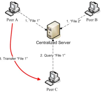
Figure 2.1 The centralized P2P architecture.
The easiest way is to place a centralized server for query regarding the location of the
file. As Figure 2.1 shows, peer A and B inform the centralized server that they have “File 1”
and “File 2” respectively. Then, peer C asks the server “where is File 1”. The centralized
server tells peer C which then download file 1 from peer A. This type of P2P sytem is
called centralized architecture.
The centralized P2P architecture still has bottleneck on the server. If the central server
gets broken, the P2P system will be out of services. As a result, researchers proposed a
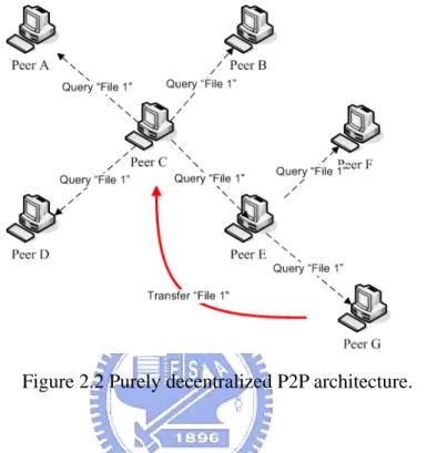
“File 1”, it broadcasts query message to all its directly connected peers A, B, D and E,
which do not have “File 1” so they broadcast the message to their directly connected peers,
recursively. Finally, peer G has “File 1” which is then sent to Peer C.
Figure 2.2 Purely decentralized P2P architecture.
The purely decentralized system can result in unnecessary packet flooding in the
network. Works have been done to combine both centralized and decentralized schemes to
take advantage of them.
2.1.3 BT revolution
BitTorrent (BT) [1] is a technology used for distribution of files much efficiently and
fast. Since BT was developed in 2001, it has become more and more popular on
file-sharing application and attracted a large number of users in the Internet world.
The most significant contribution of BT is breaking a file into many smaller pieces in
fixed size, called chunks, for sharing. A user can download a file from other peers who own
the different chunks of the file simultaneously. The novel idea greatly improves download
The “Tracker Server” in BT system logs who are downloading the file and helps peers
find them out. Once a peer intends to download a file, it needs a “torrent” file which
contains the file name, size, hashing information and the URL of the tracker server. As a
result, a peer can make a connection to the tracker server by the indication of the torrent
file.
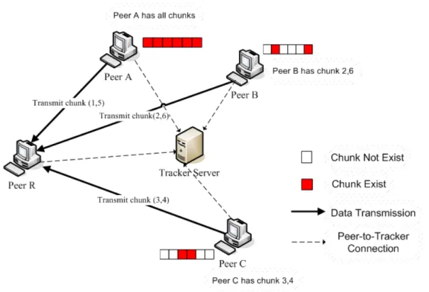
Figure 2.3 BT architecture.
As Figure 2.3 shows, every peer in BT has to communicate with tracker server, such
as peer A, B, C and R. Suppose that peer A is the “seed”, which is the source of the file. At
the moment peer R intends to download the file, it asks tracker server and get a response
which indicates that peer A has all chunks, peer B has chunk 2 and 6, peer C has chunk 3
and 4. Now, peer R can receive chunk 1, 5 from A, chunk 2, 6 from B and chunk 3, 4 from
C simultaneously. With the aid of tracker server, peer can download different chunks of the
file from different peers and greatly improve the efficiency on downloading a file.
aspects. The concept of “chunk” is dividing a file into smaller pieces. This is used for many
areas. Some P2P IPTV systems employ the concept of BT and divide video stream into
fix-sized chunks for peer sharing. We will discuss P2P IPTV system in more detail in the
following sections.
2.2 Video Streaming Architecture
The popular network services have been shifted from server based Web, E-Mail to
P2P based VoIP, IPTV, etc. Due to the large volume of streaming video in IPTV, which still
needs further advanced technology to improve the quality of service provisioning. IPTV
becomes the next significant application on Internet. In order to provide TV service on
Internet, the most institutive approach is through centralized server. However, as described
above, client-server architecture has its restrictions. To overcome these drawbacks,
engineer and scientists try to make IPTV provisioning based on P2P architecture. We will
take a close look on the two architectures and its pros and cons in the following
sub-sections.
2.2.1 Centralized server architecture
IPTV based on centralized architecture is very similar to the traditional
“Client-Server” service. The only difference is that the server provides video contents
instead of traditional text and images.
However, the IPTV server(s) is unable to accommodate too many viewers
simultaneously. Considering a scenario where few hundreds or even thousands of viewers
intend to watch 500kbps bit-rate video stream. The head end of IPTV must have at least
50Mbps network bandwidth. It is not only a heavy load on both Internet core and source of
architecture, IPTV has the potential to overwhelm the Internet backbone with its traffic. We
need to consider different approaches to overcome overwhelming problem.
2.2.2 IP layer multicast
The first idea to overcome overwhelming problem is to employ IP network multicast
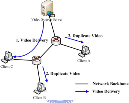
[10] scheme on routers. Figure 2.4 shows the architecture of router multicast scheme.
Figure 2.4 IP layer multicast for video stream delivery.
In Figure 2.4, the video server delivers video streams to a set of viewers, client A, B
and C. Instead of delivering to every viewer a copy of video content, server only sends
video content to a multicast address. Whenever a peer is interested about some video
content, it registers into the multicast address group. The video content will be duplicated
by router and delivered to every viewer who has joined the group.
Although this scheme can avoid the overwhelming problem, router setting is the key
issue here. The routers in core network belong to different ISPs. A large portion of them do
not enable router multicast ability nowadays. In addition, the dynamic spanning tree(s)
2.2.3 P2P architecture
Another method to overcome the overwhelming problem is to minimize the usage of
centralized server(s). Service provisioning of IPTV gradually moves to P2P scheme. IPTV
utilizes the characteristics of P2P, in which every peer downloads and shares video contents
with each other to reduce the load of centralized server(s). The basic idea is that source
server provides contents to a small subset of peers which again distribute the received
contents to other peers who have requested for the same contents, as shown in Figure 2.5.
The major difference between this scheme and router multicast is that P2P scheme runs on
application level, thus it could be system independent.
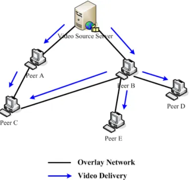
Figure 2.5 End system multi-cast on video stream delivery.
Experiment shows that IPTV based on P2P scheme can reduce about 84% of source
upload traffic and only increase 8% of peer upload traffic [16]. As a result, IPTV based on
P2P scheme can significantly increase the scalability and reduce the load of server(s), and
2.3 Tree-Based Overlay
Two major types of P2P architecture are used to IPTV streaming applications:
tree-based and mesh-based overlay. The former is for media streaming from root (source
node) to branches and leaves; while the latter is for massive parallel content distribution
among peers.
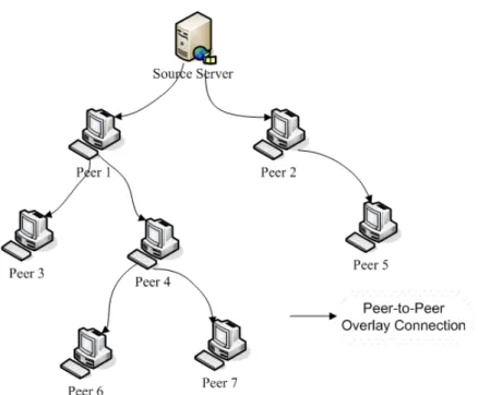
2.3.1 Single tree overlay
On tree-based overlay, as Figure 2.6 shows, peers were located in branch and leaf
nodes. Media streams are pushed from root to every leaf node. Whenever a branch node
received media stream from their parents, they also deliver the stream to their children
nodes immediately. This is an efficient structure in terms of bandwidth and delay
optimization. However, there are two fundamental drawbacks on tree structure, as
described in the following.
Dynamics of system configuration: this is caused by the frequent joining and leaving of peers, may affect the integrity of tree architecture. In case of a peer which is near to root
node crashes, it could lead to the termination of services for all downstream sub-trees. As a
result, many tree repairing algorithms have been proposed to maintain tree integrity [8][17].
Minimized upload bandwidth: since the leaf nodes do not contribute any upload bandwidth, it leads to bandwidth waste.
Figure 2.6 P2P architecture - Single tree overlay.
One of the first end systems for video streaming is Narada [9], which builds a
source-rooted minimum-delay tree for delivering video contents. NICE [8] is a P2P
streaming system which was designed for large number of receivers. It uses its own
hierarchy information for routing.
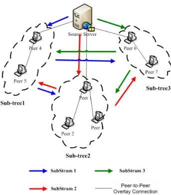
2.3.2 Multiple tree overlay
Multiple tree architecture resolves the aforementioned problems. The source server
delivers a sub-stream of video to each of its disjoint trees. As Figure 2.7 shows, multiple
tree overlay divides a tree into 3 sub-trees. Source server also divides a video stream into 3
sub-streams which are transferred to the 3 sub-trees, in which peers exchange their own
Figure 2.7 P2P architecture: Multiple tree overlay.
Multiple tree overlay can reduce source server’s high upload-bandwidth requirement.
In this example, source server just needs to upload 1/3 of video data than that in single tree
overlay. However, multiple tree architecture is more complex for implementation and
maintenance.
2.4 Mesh-Based Overlay
The concept of mesh based overlay is very similar to BT mechanism. A newly joined
peer in mesh overlay first contacts the tracker server to obtain the list of peers which are
either downloading or have downloaded video chunks. Peers in the system exchange the
chunks they have, buffer maps and the availability of chunks, as well as to inform other
peers which chunks is has. A peer’s partners may contain normal peers or video source
node. Therefore, video streams can be delivered to all other peers.
should be the biggest advantages of mesh based overlay. Unlike tree-based overlay, the
system needs not to spend effort to maintain integrity of architecture and never have to
worry about the joining or leaving of peers. Without requiring any algorithm for repairing
or maintenance, it is much easier to implement and maintain the system.
Figure 2.8 P2P Architecture: Mesh-based Overlay
Gnustream [13] is a mesh based P2P video streaming system which delegates basic
P2P services to Gnutella. CoolStreaming [19] is a data-driven overlay network for P2P live
media streaming. Media streams are split into fixed-size chunks for delivery. Every peer
owns a 120-bits buffer map for indication of the chunk availability.
The major difference between BT and P2P video streaming application is that the
latter has constrained packet delivery time. If the packet delivery time misses the deadline,
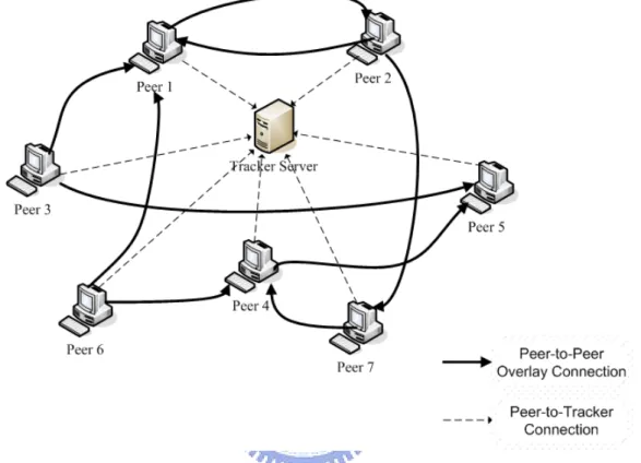
2.4.1 Mesh-based system architecture
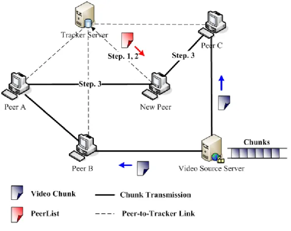
In this section, we describe mesh based overlay system in more detail. As shown in
Figure 2.9, the tracker server logs all peers’ information, including IP address, port number,
selected channel, etc. Peers in the system have to keep connection with tracker server and
periodically report their status. The tracker server will kick out those peers that did not
report their status.
Figure 2.9 Mesh-based system architecture.
In mesh based overlay system, video source server divides video stream into many
“chunks” with equal size for broadcasting. Whenever a new peer joins the system, the first
step is to connect to tracker server and register its information. After successful registration,
the new peer would select a channel to watch. The tracker server will randomly select a
certain number peers who are watching the same channel, add them into PeerList and send
PeerList includes peer’s IP address, port number, and so on. The new peer then establishes
the partner relationship with a subset of peers in PeerList, as shown in step 3. In Figure 2.9,
the partners of the new peer are Peer C and Peer A. These peers periodically exchange
“buffer map”, the availability of chunks, with each other and received chunks from or
transmit chunks to partners. Peers may also establish partner relationship with video source
server to obtain fresh video chunks. Using a chunk scheduling algorithm, each peer
requests the chunks required for the coming playback from its partners.
2.4.2 Peer adaptation
After establishing partnership with other peers and starting P2P video stream
mechanism, a peer may seek more suitable new partners with larger network bandwidth for
improving playback quality. For instance, some partners may leave the system suddenly or
part of network backbone gets broken, these will interrupt the service connection between a
peer and its partner.
The mechanism described above is called Peer Adaptation. The mechanism regarding
how and when to perform peer adaptation is quite different for various P2P video streaming
systems.
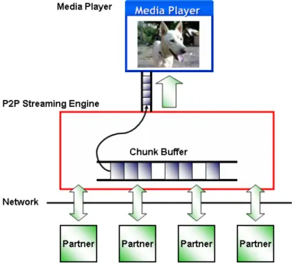
2.5 Mesh-Based Software Components
Figure 2.10 shows the mesh based system software components. The peer software
components include media player and P2P streaming engine. The streaming engine is the
main component on peer software which is a cooperator on media player and partners on
network wide. Streaming engine has to collect chunks from partners or provide chunks to
Figure 2.10 Software components of mesh-based peer application.
2.5.1 P2P streaming engine
The P2P streaming engine is the core of peer software which has to (1) Receive
chunks or share chunks with partners; (2) Exchange buffer maps with partners for
indication of chunks a peer currently buffered; (3) Duplicate media chunks to media player
for playback.
A peer can request buffer map from its current partners and requests chunks from
partners who advertised in buffer map. After downloading chunks, the streaming engine
stores it in “chunk buffer”, as shown in Figure 2.10. The method on choosing which partner
for chunks downloading is the “scheduling” algorithm. Different mesh P2P streaming
systems have their own algorithm. The strategy of scheduling are probably deadline-first,
slow-bandwidth first and so on. P2P streaming engine also has a mechanism for searching
new peers to establish partner membership in case of churn or insufficient upload
2.5.2 Media player
Media player is used for playback media which is sent by the streaming engine.
Firstly, media player sends an HTTP request to streaming engine. Then, the streaming
engine converts video chunks into a file with the format that media player can recognize.
Before playback, media player always needs to buffer a short interval of media for
continuity concern. If the chunk did not arrive before playback deadline, it will result in
“gaps” on media playback. Note that the uncompleted chunk can also be converted into
media stream but with low or even bad quality during playback.
2.6 Long Start-up Delay Issue
The traditional cable television (CATV) has its own broadcast system. Video service
provider broadcasts every channel’s video contents through private cable network without
any digital data. As a result, a user can watch video content immediately as soon as TV is
turned on and there is almost no playback delay in channel switching.
However, the video content transmission through best-effort IP network is unlike that
in traditional TV system. There is a huge number of Internet users contending network
bandwidth and other resources. This causes unpredictable video packet delay and jitter, and
results in no guarantee on the arrival time, transmission time and the order of content
delivery of video content. To overcome these problems and to achieve smoothness in video
playback, a receiver always pre-caches and buffers certain volume of video content before
it starts playing back. Compared to traditional TV system, a client in IP network needs to
buffer quite a bit of video content before it starts up.
The start-up delay is the time interval between a user requesting a video program and
first showing up of the requested video frame. The main course of start-up delay is the time
always need to buffer more video contents compared to original client-server architecture
due to peer’s dynamic behavior, that is peer joining or leaving the system randomly. In
addition, the mesh overlay system has longer start-up delay because the peer in mesh based
overlay have no specific video content source and need to pay more time on seeking and
determining the content source. Start-up delay becomes a serious issue in mesh based
overlay P2P IPTV system. On the other hand, the behavior on switching video channel is
something like restarting the video stream. Peer application has to re-cache buffer the video
stream for continuous playback.
In mesh-based P2P IPTV system, the existing approach is that a new peer starting to
download chunks from partners which are randomly selected by tracker server is not a good
idea. New peer has no choice to download from better candidates. In addition, the large
amount of video content for strat-up with weak downloading capacity causes long start-up
delay. We need more efficient mechanism to resolve this issue.
2.7 Related Works
As mentioned above, the user’s experience on traditional TV system and P2P video
streaming system are quite different. P2P video streaming system can not provide short
start-up delay like traditional TV and channel surfing experience. This may affect user’s
willing to watch P2P video program. To solve the start-up delay issue, many schemes have
been devised to reduce the delay. Some video streaming applications play pre-built-in
commercial advertisements back on start-up duration, so that the user won’t feel any
start-up delay. However, it does not really solve the problem from the technical point of
Figure 2.11 Reducing start-up delay by centralized server.
Most of P2P IPTV service providers nowadays established several centralized servers
which have guaranteed upload bandwidth to reduce start-up delay. Specifically, the first
few seconds of video chunks were downloaded from centralized servers while peer
application launched and other video chunks are obtained through P2P mechanism. As
Figure 2.11 shows, the stream server firstly provides video chunks to peer A on start-up.
Peer A receive chunks from P2P system after start-up.
From the service provider point of view, this could be the easiest way and could
guarantee the start-up delay. Further, a centralized mechanism can be maintained easily.
However, this could also cause several problems. First, service provider has to pay higher
cost for server maintenance. Second, centralized servers are unable to accommodate
unlimited number of peers joining the system simultaneously, and peers have to wait until
other peers finished receiving of video chunks from centralized servers. This may result in
the slower peers unable to join the system.
To overcome the long start-up delay problem and centralized servers problem
mentioned above, we propose a novel scheme for P2P video streaming application. Peers
“super-peers” to tracker server. The tracker server collects these admitted “super-peers”
recommended by peers and checks new peer’s IP address to know who were peer’s
neighbors. Therefore, tracker server dispatches admitted “super-peers” and new peer’s
“neighbors” to the new peer. Instead of obtaining video chunks from centralized servers in
the first few seconds, new peer obtains video from admitted “super-peers” and its
“neighbors” in start-up duration. The major benefit of this scheme is providing short
Chapter 3 Proposed Approaches
As mentioned in previous chapters, IPTV based on P2P network overlay requires
longer start-up delay than client-server architecture to satisfy video playback quality. Long
start-up delay problem is much serious in mesh based P2P network overlay than tree-based
due to the lack of fixed source server to provide video contents. As a result, 1) a new peer
in mesh based overlay may acquire chunks from un-suitable partners. However, the 2)
centralized servers for start-up approach can not accommodate too many peers
simultaneously. We propose a new approach to address these two major problems on P2P
video streaming application.
In this thesis, we focus on addressing mesh based P2P IPTV long start-up delay
problem because it is the major P2P architecture in current market and its long start-up
delay is more serious than others. We will describe our proposed scheme in detail in the
following sections.
3.1 Design Philosophy
To reduce start-up delay, the most intuitive idea is downloading every video chunk
from the one with the highest upload bandwidth. Therefore, we ask a new peer to download
video chunks from “super-peers” and/or “neighbors” when it starts up. Finding out and
determining who are super-peers and neighbors become another important issue in this
3.2 Main Scheme
We claim that there are three phases in P2P IPTV peer application. These are Closed,
Start-Up and Steady phases.
Figure 3.1 Peer application phases.
Users intend to watch P2P IPTV and launch the peer application, and this action
causes system to transit from “Closed” phase to “Start-Up” phrase. The first task peer
application has to do is caching enough video in the buffer in start-up phase for playing
back. Peer application then transfers from Start-Up to Steady phase after collecting enough
video contents in buffer. In Steady phase, peer application performs normal P2P IPTV
function, receives chunks to and transmits chunks to partners. If s peer application switched
channel, it returns back to Start-up phase and recollect new channel’s video content. Peer
application may go back to Closed phase and shut down the application.
In the following subsections we describe our proposed approaches in more detail. We
propose two mechanisms, Super-Peer Recommendation Mechanism and Power Start-Up
Mechanism to solve the long start-up delay problem. The former is the method to
recommend super-peer among all peers. The latter is a fast start-up method to reduce long
3.2.1 Super-peer recommendation mechanism
Notation Description Formula
CA(i) Number of chunks downloaded
from partner i to peer A S The fixed size of a chunk
TA(i)
Time consumed for peer A to download CA(i) from partner i
RateA(i)
The peer A’s estimated average transmission rate of downloading C(i) from peer i
) ( / * ) ( ) (i C i S T i RateA = A A
N(A) The number of partners of peer A
ADC(A) Peer A’s average number of downloaded chunks from A’s partners ) ( / ) ( ) ( ) ( 1 A N j C A ADC A N j A
∑
= = Table 3.1 Notations list.A peer who has large upload capacity can be a super-peer. In this section, we will
describe how to determine a super-peer and recommend it to tracker server.
The first criterion of super-peer should be with high upload bandwidth. To determine
a peer’s upload capacity is difficult. We use an indirect method to measure a peer’s upload
capacity by other peers. Every peer measures its partners’ data transmission rate ( RateA(i) ),
as Table 3.1 shows. We determine a peer’s partner’s RateA(i) by estimating the spent time
(TA(i)) on transmitting chunks from its partner. The estimation worked on the receiver side
of the chunk. For instance, peer A has a partner i which transmits 40 chunks to A in 10
seconds, suppose every chunk size is S, which is 512 kb, then the transmission rate
( RateA(i) ) of partner i estimated by A is 40*512/10=2048kbps. We claim that a partner can
be recommended by a peer to tracker server if it satisfies the following three criteria:
First, a partner’s transmission rate must be no less than video stream’s default bit rate.
(1.)
Rate
A(
i
)
≥
DefaultBit
Rate
Although partner i satisfies (1.), it could also lead to a problem. Think about partner i
transmit too few chunks to peer A in a very high rate but the rate between partner i and peer
A is not so fast in average. This can lead to peer A recommends unsuitable partner i. To
avoid this problem, peer A will not recommend its partner i if too few chunks can be
downloaded from i by A. So, we use the following formula instead:
(2.) CA(i)≥ ADC(A)
The super-peer is responsible for forwarding chunks to new peer on start-up. We have
to make sure that the super-peer is still alive in the system. So, the third criterion is
(3.) Partner i is currently alive.
Figure 3.2 Illustration of peer recommendation.
In every time interval (I), say 300 seconds, all peers have to recommend its partners
which have been connected during the duration I to tracker server. A peer can recommend
3.2 shows, we assume the current time is 300th seconds, the video stream default bit-rate is 512 Kbps, peer A has to recommend its partners as super-peers to tracker server. It has 4
partners as candidates at time 300th second. Peers B and F were peer A’s partner during 40th to 120th second and 80th to 290th second respectively. We assume peer B, E and G satisfy criteria (2.) and (3.). At this point, peer A will recommend peer B, E and G to tracker server
as super-peers because their rates satisfy criterion (1.).
Figure 3.3 Illustration of peer recommendation in tracker server.
The tracker server records recommended super-peer candidates from every peer in the
system. Every time interval (I), it updates these candidates into “SuperPeerList”. As Figure
3.3 shows, peer A recommends partner X and Y. Peer B recommends partner G and K. Peer
C recommend no one. The tracker server records X, Y, G and K. Tracker server will
substitute X, Y, G and K into SuperPeerList every time interval I.
There are several important issues to be discussed. First, a peer can not recommend
itself because it does not know its own upload bandwidth estimated by other peers. Another
issue is that a peer can not recommend its neighbor peers because neighbor peers always
3.2.2 Power start-up mechanism
In the previous section we describe the tracker server regarding how to collect high
bandwidth super-peers in SuperPeerList. In this subsection, we propose a “Power Start-Up
Mechanism” to reduce start-up delay by utilizing the super-peer in SuperPeerList.
Figure 3.4 Illustration on power start-up.
The core concept of Power Start-Up mechanism is that when a new peer joins the
system, it fills its video buffer with chunks coming from super-peers and neighbors. As
Figure 3.4 shows, after a newly joined peer registered to the tracker server, it receives a
PeerList transmitted by the tracker server which contains not only randomly selected peers
but also super-peers and neighbor peers. The new peer starts to download video chunks
only from super-peers and neighbor peers at start-up phase. It downloads no chunks from
randomly selected peers in this phase. With the assistance from neighbor and super-peers,
Power Start-Up can greatly reduce start-up delay. On the other hand, we can reduce the
Figure 3.5 Super-peer, neighbor and random peer selection.
Suppose that the number of connections established by new peer in the existing
scheme is L. The tracker server in the existing scheme has to provide more than L randomly
selected peers in PeerList. We do not change the number of connections in our new scheme.
As a result, in Power Start-Up, the tracker server dispatches L/2 super-peers and neighbor
peers, and the number of randomly selected peers is still more than L.
As Figure 3.5 shows, the tracker server randomly selects super-peers from
SuperPeerList and put them into PeerList. On the other hand, to determine who are the new
peer’s neighbor peers, the tracker server compare new peer’s IP address with all peers in
the system. The tracker server chooses top L/2 peers whose IP address have longest prefix
matched due to the IP address distribution policy.
After finishing the start-up phase, a peer gradually reduce the dependency on
super-peers and neighbor peers, it then could re-establish partnership with peer adaptation
3.2.3 Scheme related issues
The assistance of super-peer can be always greater than randomly selected peers
because of the dynamic load balance ability. As Figure 3.6 shows, peer B has a partner A,
peer A’s high upload rate causes peer B to recommend A to tracker server in time interval 1,
i.e. (a.).
Figure 3.6 Illustration of dynamic load balance.
However, peer C joins the system and make partnership with peer A. As a result, peer
A’s upload rate becomes lower than that in the first criterion and no one will recommend
peer A to tracker server in the second time interval, i.e. (b.).
When peer D joins the system in the third time interval (c.), the tracker server will not
dispatch peer A in the PeerList as super-peer because peer A is not recommended in time
interval 2. This results in peer D to launch Power Start-Up mechanism which is not from
peer A. Peer D launches Power Start-Up from other super-peers, probably peer X. We can
claim that Super-Peer Recommendation Mechanism features dynamic load balance ability
and can guarantee the super-peer upload performance.
The super-peers recommended by every peer in the system may not be really a
the connection between peer A and C may be slow. As a result, the super-peers in PeerList
probably can not offer high upload capacity to certain peers. However, it is unlikely that
every super-peer chosen in PeerList by tracker server is a weak peer.
The load of super-peer won’t be heavy because it only helps new peers at Start-up
phase. In Steady phase, a new peer will gradually reduce the dependency on super-peer.
However, it is possible that the super-peer still become a new peer’s partner if the new peer
performs peer adaptation and makes partner relationship with the super-peer.
3.3 Software Viewpoint
In this section, we will evaluate our mechanism from software point of view. This can
improve reader’s understanding of our proposed schemes in different aspects. We will
demonstrate the skeleton of tracker server and peer application software in following
sub-sections.
3.3.1 Tracker server algorithm
Tracker Server Pseudo-Code
NextSuperPeerList=[] SuperPeerList=[] Infinit_Loop { Switch ( New_Event) { Case New_Peer_Join: Create PeerList
Randomly Select L/2 nodes from SuperPeerList into PeerList Randomly Select L nodes from all peers into PeerList
Choose Neighbor Peers into PeerList Delivery PeerList to New_Peer Case Peer_Recommend:
Case Every_Time_Interval: SuperPeerList <= NextSuperPeerList Clean NextSuperPeerList Case …: … } }
Table 3.2 Pseudo-code of tracker server.
Tracker server has to deal with three major tasks: new peer joining, peer
recommendation of super-peers and SuperPeerList update. We present it in pseudo code
style in Table 3.2.
3.3.2 Peer application algorithm
Peer Application Algorithm
Register to tracker server Go to START_UP phrase
START_UP phrase:
Send request channel to tracker server Receive PeerList from tracker server Start Power Start-Up
IF Collect enough buffer Go to STEADY phrase STEADY phrase: Infinit_Loop { Switch (New_Event) { Case Channel_Switch:
Go to START_UP phrase Case Every_Time_Interval:
Recommend partners to tracker server Case …:
… }
}
Table 3.3 Pseudo-code of peer application.
Table 3.3 shows the algorithm of peer application’s behavior in pseudo code. Firstly, peer
application transits to Start-Up phase and launches Power Start-Up. After collecting enough
chunks in video buffer, peer application transits to Steady phase. The algorithm can
re-transit into Start-Up phase while user switches channel. In Table 3.3, we ignore the
buffer map and chunks exchange in the pseudo code.
3.4 Summary
Super-Peer recommendation mechanism allows tracker server to collect super-peers
candidates in the system. Power Start-Up mechanism employs the collected super-peers and
neighbor peers’ assistance to reduce the start-up delay experienced in P2P IPTV system.
Besides pros mentioned in the previous sections, our proposed schemes feature the
following benefits:
1. It can reduce core network traffic due to neighbor peers’ assistance.
2. Reducing start-up delay.
3. Avoid heavy load in super-peer.
4. Distributed architecture compared to centralized server architecture.
Chapter 4 Simulation and Numerical Result
We designed two experiments to validate our new proposed scheme. The first
experiment is aim to evaluate the Super-Peer Ratio (SPRatio) on “Super-Peer
Recommendation Mechanism”. SPRatio is the ratio of real super-peers in all recommended
super-peers in SuperPeerList. Not all of recommended super-peers in SuperPeerList always
has great upload rate due to mis-recommend from peers. SPRatio is an important factor that
affects the start-up delay in our proposed scheme. Another experiment is used to estimate
the start-up delay in our new approach.
4.1 Simulation Design
In [18], it shows the network type of CoolStreaming users on 27 September, 2006, as
in Table 4.1.
Network Type Description Ratio
Direct-connect Peers have public addresses with both
incoming partners and outgoing partners. 10.9%
UPnP Peers have private addresses with both
incoming partners and outgoing partners. 18.7%
NAT Peers have private addresses with only
outgoing partners. 65%
Firewall Peers have public addresses with only
outgoing partners. 5.41%
Table 4.1 Network type distribution of CoolStreaming users.
CoolStreaming gives us an important reference data of users’ network types on
4.1.1 Experiment on super-peer recommendation mechanism
We write a program in Python [4] language for building the network environment
described above and validate the performance of “Super-Peer Recommendation
Mechanism” on steady state. To simplify our experiment, we classify network into three
types, direct-connect, UPnP and NAT. We construct a network environment which contains
1,000 peers. Every peer belongs to one of three network types. According to [18], 10.9% of
nodes are direct-connect, 18.7% of nodes are UPnP and 70.4% are NAT. Each of these
network types has different upload capacity. Direct-connect type has the range from 2Mbps
to 8Mbps, UPnP are randomly chosen from 128, 256, 512, 1024Kbps and NAT is with the
range from 0 to 128Kbps. We show the parameters in Table 4.2. In our network
environment, there are 109 Direct connect nodes, 187 UPnP nodes and 704 NAT nodes.
Network Type Distribution Upload Capacity Num of Peer
Direct-connect 10.9% 2~8Mbps 109
UPnP 18.7% [128,256,512,1024]Kbps 187
NAT 70.41% 0~128Kbps 704
Total 100% 1000
Table 4.2 Parameters in the simulation environment.
Every peer randomly chooses 10 nodes as its video chunk source partners from these
1000 nodes. To simplify the simulation, we ignore peer adaptation mechanism and peer
always downloads video chunks from its 10 source partners. On the other hand, every peer
has to upload video chunks to several peers. The default bit-rate of a video stream is
512Kbps. After finished the establishment of peer’s network topology, we start the P2P
video streaming protocol and evaluate the performance of Super-Peer recommendation
Figure 4.1 Simplified global view of simulation environment.
In the experiment, every peer will recommend its partners who satisfy Super-Peer
criteria, as described in Section 3.2.1, to the SuperPeerList on tracker server. System
records every recommended super-peer and check whether it is a super-peer or not. Finally,
we can determine the ratio of super-peer in SuperPeerList. Figure 4.1 is a simplified global
view of the simulation environment. Some peers will recommend its partners to tracker
server.
4.1.2 Experiment on start-up delay
We measured start-up delays in this experiment. At the moment the previous
experiment finishes, we make a new peer to join the system. Currently, there is no specific
method on partner dispatching for newly joined peers. In the existing scheme newly joined
approach, Power Start-Up Mechanism, new peer’s partners are chosen from SuperPeerList
and its neighbors. These two different peer selection approaches are used to simulate the
existing schemes and our proposed schemes. There are 10 randomly chosen partners in the
existing approach; while in the new approach, there are 5 partners from SuperPeerList and
5 partners from neighbor peers.
Figure 4.2 The existing approach and the new approach.
After partners have been chosen, we put these partners and their upload capacity
parameters into NS2 to measure the start-up delay of both the existing and the proposed
approach. We also compare two start-up delays with each other and how much benefit
brought from Power Start-Up Mechanism.
4.2 Simulation Program
Table 4.3 shows the source code of the Peer Class. Every peer has its identifier and type.
The type can be one of “DirectConnect”, “NAT” or “UPnP”. Every peer has a randomly
Simulation Program - Peer Class
Class Peer:
def __init__(self, node_type, nid):
self.node_type = node_type # ”DirectConnect”, ”NAT” or ”UPnP”
self.nid = nid # Node id
self.upload = self.gen_up_bandwidth() #upload capacity
self.source=self.gen_source() # random choose 10 sources
self.recv_bwth=[] # record sources upload bandwidth
self.dest =[] # downstream peers
self.pay_bwth=[] # need to pay to downstream peer
self.remain=self.upload # remained bandwidth
Table 4.3 Source Code – Peer Class
Table 4.4 demonstrates the calculation of SPRatio. Variable SuperPeerList is a list
that stores recommended super-peers and is a global scope variable.
Simulation Program – SPRatio Calculation
SuperPeerList=[] #global scope
…
rn=len(SuperPeerList) # num of SuperPeerList
m2=len(M2_nodes) # >2M SP
k512=len(K512_nodes) # >512K SP
print " Num of SuperPeerList = %d, 2M SP= %d, 512K SP = %d" %( rn, m2, k512)
print "SPRatio=%.4f, 2M SPRatio= %.4f, 512K SPRatio= %.4f" %
( (m2+k512)/float(rn), float(m2)/rn, float(k512)/rn)
4.3 Numerical Results
We show our experiment results in this section. The first observed point is Super-Peer
Ratio (SPRatio) which can demonstrate the performance of Super-Peer Recommendation
Mechanism. Another observation point is how much start-up delay can be reduced in our
proposed scheme.
4.2.1 Super-peer ratio
As we described above, a super-peer must have the upload capacity larger than
default bit rate of the video stream, i.e. 512Kbps. Not all of recommended super-peers
(RSPs) in SuperPeerList will become super-peers. In other words, some of recommended
super-peers’ upload capacity is too low to play the role as a super-peer.
Figure 4.3 Illustration of super-peer and fake super-peer in SuperPeerList.
As Figure 4.3 shows, SuperPeerList records all RSPs in the system. However, some
of RSPs do not have sufficient upload capacity. These peers are not proper to act as
super-peers. We introduce a new term called Super-Peer Ratio (SPRatio), which is the ratio
of real super-peers on all recommended super-peer candidates, i.e. the ratio of blue colored
RSP SP(>2Mb) SP(>512Kb) SPRatio Experiment 1 148 68 25 62.84% Experiment 2 153 70 23 60.78% Experiment 3 140 65 34 70.71% Experiment 4 139 68 26 67.63% Experiment 5 133 53 30 62.41% Average 142.56 64.80 (45.45%) 27.60 (19.36%) 64.81%
Table 4.5 Experiment result of Super-Peer Ratio.
Table 4.5 shows the experiment result. On average, there are 142.56 peers in 1000 peers’
network system are recommended to SuperPeerList. The Super-Peer Ratio (SPRatio) is
about 64.81%. In addition, the RSPs in SuperPeerList whose upload capacity larger than
2Mbps is about 45.45%, larger than 512Kbps but smaller than 2Mbps is about 19.36%.
SPRatio
SP(>2M) 46% SP(>512K) 19% Fake SP 35% SP(>2M) SP(>512K) Fake SPFigure 4.4 Peer Distribution in SPRatio
SPRatio is an important factor to determine the performance of Super-Peer
peers with high upload capacity to newly joined peer in Power Start-Up Mechanism. This
may cause the new peer unable to take advantage of super-peers’ assistance and reduce the
start-up delay. Our experiment shows that SPRatio is about 64% which means that our
Super-Peer Recommendation Mechanism has sufficient capability to collect super-peer into
a list for reducing start-up delay in Power Start-Up.
4.2.2 Start-up delay
In this experiment, we set the start-up delay as the consuming time on filling the
video buffer. The size of buffer is a variable ranging from 10 to 30 seconds of video chunks.
For example, the buffer size is 10 seconds of video stream whose default bit-rate is
512Kbps. The start-up delay is the time on filling 512Kbps*10 = 5120Kb buffer.
We classify the start-up delay under two environments, residential and campus. In
residential environment, the maximum network download capacity is limited to 2Mbps. In
addition, we assume no neighbor peer in residential environment. The following table is the
simulation result in residential environment.
Start-Up Delay on Residential Environment
Buffer (sec.) 10 15 20 25 30
Existing Scheme 9.087 15.119 17.469 24.181 30.347
Proposed
Scheme 3.553 5.039 6.914 8.447 9.909
Table 4.6 Simulation result: start-up delay on residential environment.
The previous experiment result shows that SPRatio is about 65% which means newly
joined peer that employs Power Start-Up Mechanism can reach 3 peers whose upload
about only 1 peer whose upload capacity is larger than 512Kbps because direct-connect
peer only occupy 10.9%. Finally, the simulation result shows that our proposed scheme can
reduce about 60% of start-up delay time compared to the existing approach. We claim that
our approach can reduce start-up delay significantly.
10 15 20 25 30 0 5 10 15 20 25 30 Residential Environment Sta rt-up De lay ( se c .) Buffer (sec.) Existing Scheme New Scheme
Figure 4.5 Simulation result: start-up delay on residential environment.
In campus network environment, a peer’s download capacity is sufficiently high so
we assume that it is unlimited. Assume there are 50 neighbor peers in the simulation system.
These cause both existing and new approaches in campus environment to achieve smaller
start-up delay. Table 4.7 shows the simulation result in campus environment.
Start-Up Delay on Campus Environment
Buffer (Sec.) 10 15 20 25 30
Existing Scheme 8.651 13.88 17.356 21.361 23.929
Proposed
Scheme 1.674 1.79 1.855 2.022 2.539
10 15 20 25 30 0 5 10 15 20 25 30 Campus Environment S ta rt-up De la y (s e c .) Buffer (sec.) Existing Scheme New Scheme
Figure 4.6 Simulation result: start-up delay on campus environment.
In campus environment, our proposed scheme still features smaller start-up delay than
the existing scheme. We can observe that our proposed scheme in campus environment
experience much smaller start-up delay, which is about 3 times faster than that in residential
environment. This is because peers in campus environment gain the assistance from
neighbor peers in academic network which has much higher bandwidth resource.
4.4 Summary
According to the previous two experiments, the Super-Peer Recommendation
Mechanism can reach large SPRatio which makes newly joined peer to launch Power
Start-Up and obtain more help from super-peers. As a result, our proposed scheme
averagely can reduce about 60% start-up delay compared to the existing approach. On
certain environments, such as campus, a new peer can reduce more than 85% of start-up
delay because a peer can obtain helps from its neighbor peers. In summary, our new
Chapter 5 Conclusion and Future Works
P2P IPTV system becomes more and more popular in recent years. However, its long
start-up delay seriously affects user’s willing to watch P2P IPTV unless it is free of charge.
Basically, we can reduce start-up delay by the assistance from super or neighbor peers. In
this thesis, we proposed two mechanisms to reduce start-up delay.
The first one, called Super-Peer Recommendedation Mechanism, which is a
distributed mechanism, and runs on every peer. The mechanism can help each peer
recommend their partners who have high upload rate as super-peers to tracker server.
Tracker server keeps the information of recommended super-peers into local list.
The second mechanism we proposed is Power Start-Up Mechanism. When a new peer
joins the system, the tracker server dispatches super and neighbor peers to it, where
super-peers are recommended through Super-Peer Recommendation Mechanism descript
above. The newly joined peer downloads video chunks only from super and neighbor peers
at Start-Up phase. This can help new peer fully utilize super and neighbor peers high
upload capacity and reduce the start-up delay.
To evaluate the efficiency of our proposed scheme, we establish a simulation
environment implemented in Python language to simulate Super-Peer Recommendation
Mechanism. The result shows that Super-Peer Ratio (SPRatio) is more than 60% which
means tracker server can collect more super-peers than the existing approach. In addition,
we simulate both existing and our proposed approaches to calculate start-up delay in NS-2
simulator. In residential environment, our approach can reduce 60% of start-up delay
compared to that in existing approach. In campus network environment, we can reduce
87% of start-up delay than the existing approach.
This can cause start-up delay problem become more serious. We will improve our
Super-Peer Recommendation mechanism to reach even higher Super-Peer Ratio and make
new peer to start-up in a very fast way. On the other hand, the collected start-up buffer is a
critical issue. We will focus on the estimation regarding what size of start-up buffer can
reach a balance. Too low in size can lead to insufficient buffer which degrades video quality.
On the other hand, too high in size may cause start-up delay too long. There must be a way
References
[1] BitTorrent,http://www.bittorrent.com/. [2] PPLive,http://www.pplive.com/. [3] PPStream,http://www.pps.tv/. [4] Python,http://www.python.org/. [5] Skype,http://www.skype.com/. [6] SopCast,http://www.sopcast.com/. [7] TVants,http://www.tvants.com/.[8] Banerjee, S., B. Bhattacharjee, et al."Scalable application layer multicast." Computer Communication Review 32(4): 205-217, 2002.
[9] Chu, Y. H., S. G. Rao, et al."A case for end system multicast." Ieee Journal on Selected Areas in Communications 20(8): 1456-1471, 2002.
[10] Deering, S."Multicast Routing in Internetworks and Extended LANs." ACM SIGCOMM, 1988.
[11] Hei, X., C. Liang, et al."A measurement study of a large-scale P2PIPTV system." Ieee Transactions on Multimedia 9(8): 1672-1687, 2007.
[12] Hei, X. J., Y. Liu, et al."IPTV over P2P streaming networks: The mesh-pull approach." Ieee Communications Magazine 46(2): 86-92, 2008.
[13] Jiang, X., Y. Dong, et al."GnuStream: a P2P media streaming system prototype." International Conference on Multimedia and Expo 2: 325-328, 2003.
[14] Li, B. and H. Yin"Peer-to-peer live video streaming on the internet: Issues, existing approaches, and challenges." Ieee Communications Magazine 45(6): 94-99, 2007. [15] Liu, J. C., S. G. Rao, et al."Opportunities and challenges of peer-to-peer and Internet
video broadcast." Proceedings of the Ieee 96(1): 11-24, 2008.
[16] Sentinelli, A., G. Marfia, et al."Will IPTV ride the peer-to-peer stream?" Ieee Communications Magazine 45(6): 86-92, 2007.
[17] Tran, D. A., K. A. Hua, et al."A peer-to-peer architecture for media streaming." Ieee Journal on Selected Areas in Communications 22(1): 121-133, 2004.
[18] Xie, S., B. Li, et al."Coolstreaming: Design, theory, and practice." Ieee Transactions on Multimedia 9(8): 1661-1671, 2007.
[19] Zhang, X., J. Liu, et al."DONet/CoolStreaming: A data-driven overlay network for peer-to-peer live media streaming." Proc. IEEE INFOCOM 3: 2102 - 2111, 2005.