在異質雙核心平台上設計與分析動態分工的串流播放器
59
0
0
全文
(2) 在異質雙核心平台上設計與分析動態分工的串流播放器 Dynamic Task Partition Design and Analysis of Streaming Player on Heterogeneous Dual-core Platforms. 研 究 生:廖珮晴. Student:Pei-Ching Liao. 指導教授:蔡淳仁. Advisor:Chun-Jen Tsai. 國 立 交 通 大 學 資 訊 科 學 與 工 程 研 究 所 碩 士 論 文. A Thesis Submitted to Institute of Computer Science and Engineering College of Computer Science National Chiao Tung University in partial Fulfillment of the Requirements for the Degree of Master in Computer Science Dec 2008 Hsinchu, Taiwan, Republic of China. 中華民國九十七年十二月.
(3) Abstract This thesis presents the design of an ISMA-compliant highly efficient streaming player with dynamic task partition approach for MPEG-4 video decoding on a heterogeneous dual-core embedded system. The streaming library is designed to reduce the memory bandwidth requirement for processing RTSP/RTP/RTCP network protocols. For embedded systems, the proposed design enables reception of higher data rate streams without packet losses. In the proposed design, the streaming player running on the RISC core would call the streaming library for receiving the contents, and dynamically control the partition of the video decoding tasks between the RISC and the DSP cores. The decoding tasks are assigned at run-time according to the load of each processor. The proposed design is implemented on the TI OMAP 5912 OSK development board..
(4) Acknowledge 我要感謝我的指導教授蔡淳仁博士,在老師的細心指導下,我才能夠順利完成本論 文。這兩年在嵌入式多媒體實驗室裡學習過程中,從老師以及實驗室學長、同學以及學 弟妹身上學習到很多,有了這些經驗,相信在我未來的人生中有很大的幫助。最後我想 感謝我的家人與朋友,有各位的鼓勵與支持,讓我可以順利完成碩士學業。.
(5) Contents Chapter 1. Introduction................................................. 1 1.1.. Motivation ...........................................................................................................1 . 1.2. Introduction to the OMAP 5912 Starter Kit ........................................................ 2 1.2.1. The Memory Map of OSK 5912 .......................................................................... 3 1.2.2. Inter-processor communication on OMAP 5912 .................................................4 1.3. Scope of the Thesis .............................................................................................. 5 . Chapter 2. Previous Work ............................................. 6 2.1. Static Task Partition ............................................................................................. 6 2.2. Dynamic Task Partition .......................................................................................7 2.3. RTP Streaming Libraries ..................................................................................... 9 2.4. Porting of eCos Embedded Operating System to OMAP .................................10 . Chapter 3. Streaming Player Architecture ................ 12 3.1.. System Architecture........................................................................................... 12. 3.2.. RTSP Client Module .......................................................................................... 13. 3.2.1.. The DESCRIBE Request and Reply ..................................................................14. 3.2.2.. The SETUP Request and Reply ......................................................................... 16. 3.2.3.. The PLAY Request and Reply ........................................................................... 16. 3.2.4.. TheTEARDOWN Request and Reply ...............................................................17. 3.3.. RTP Client Module ............................................................................................ 17. 3.3.1.. Buffer Design ................................................................................................... 19. 3.3.2.. RTP Receiving Module .................................................................................... 20. 3.3.3.. RTP Processing Module ................................................................................... 20. 3.3.4.. RTCP Receiving Module..................................................................................21. 3.3.5.. RTCP Processing Module ................................................................................ 21. 3.3.6.. RTCP Sending Module .....................................................................................22. 3.3.7.. Video Payload Parser ....................................................................................... 23. 3.3.8.. Audio Payload Parser ....................................................................................... 24. 3.4.. Video Decoding Module.................................................................................. 25. 3.5. Audio Decoding Module ................................................................................. 25 . i.
(6) Chapter 4. Dynamic Partition Architecture .............. 27 4.1. System Overview............................................................................................. 27 4.2. System organization on the DSP side .............................................................. 29 4.2.1. DSP Executable File Conversion ..................................................................... 29 4.2.2. DSP Memory Management Unit ...................................................................... 32 4.3. Design of Dynamic Task Partition Mechanism ...............................................33 4.3.1. Design Issues for Dual-core Application ......................................................... 34 4.3.2. System memory map ........................................................................................ 34 4.3.3. Dual-core Video Decoding Architecture .......................................................... 35 4.3.3.1.. Control Variables for Dynamic Task Partition................................................ 37 . 4.3.3.2.. Mailbox Commands ....................................................................................... 37 . Chapter 5. Experimental Results ............................... 40 5.1. Experiments on Streaming Library Performance ............................................ 40 5.2. OMAP 5912 Network Capability under eCos ................................................. 42 5.3. Experiment of Dynamic Video Decoding Task Partition ................................ 43 5.4. Experiment of Adding another Task to ARM or DSP core.............................. 44 . Chapter 6. Conclusions and Future Works ............... 47 References………………………………………….......48 . ii.
(7) List of Figures Figure 1.1 - The OSK 5912 development board and Q-VGA display module. ................ 2 Figure 2.1 - Structure of a DSP task. ................................................................................. 8 Figure 2.2 – Protocol stack in normal case and embeddedRTP structure. ...................... 10 Figure 3.1 - The system architecture. .............................................................................. 12 Figure 3.2 - The flow chart of the streaming player. ....................................................... 13 Figure 3.3 - A typical RTSP protocol session. .................................................................14 Figure 3.4 - RTP client module flowchart. ...................................................................... 18 Figure 3.5 - Relation between the circular buffer and joint the packet buffer pool. ....... 19 Figure 3.6 - The operation of the circular buffer. ............................................................ 24 Figure 3.7 - The payload parser operation. ...................................................................... 24 Figure 3.8 - Video decoding module flowchart. .............................................................. 25 Figure 4.1 - System development flowchart.................................................................... 29 Figure 4.2 - Bootloader build flowchart. ......................................................................... 30 Figure 4.3 - The address translation. ...............................................................................33 Figure 4.4 - The global memory diagram. ....................................................................... 35 Figure 4.5 - The dynamic video decoding task partition flow. ........................................ 36 Figure 4.6 - The mailbox command transaction flowchart. ............................................ 39 Figure 5.1 - The RTPLIB and the proposed streaming library performance comparisons.42 Figure 5.2 - The test setup. ..............................................................................................43 . iii.
(8) List of Tables Table 1.1 - The MPU global memory map. ....................................................................... 4 Table 1.2 - The DSP global memory map. ........................................................................ 4 Table 3.1 – The DESCRIBE request. .............................................................................. 14 Table 3.2 - The DESCRIBE reply.................................................................................... 15 Table 3.3 - The SDP with MPEG-4 format content. ........................................................ 15 Table 3.4 - The SETUP request. ...................................................................................... 16 Table 3.5 - The SETUP reply. .......................................................................................... 16 Table 3.6 – The PLAY request. ........................................................................................ 17 Table 3.7 - The PLAY reply. ............................................................................................ 17 Table 3.8 - The TEARDOWN request............................................................................. 17 Table 3.9 - The TEARDOWN reply. ............................................................................... 17 Table 3.10 - RTP packet format. ...................................................................................... 21 Table 3.11 - RTCP SR packet format............................................................................... 22 Table 3.12 - The RTCP RR. ............................................................................................. 23 Table 4.1 - Intel MCS-86 object format. ......................................................................... 31 Table 4.2 - Linker file configuration. .............................................................................. 31 Table 4.3 - The streaming player memory map. .............................................................. 32 Table 5.1 - OMAP 5912 Network Capability under eCos. .............................................. 43 Table 5.2 - The performance of the proposed streaming player. ..................................... 44 Table 5.3 - Task Partition ration of each sequence. ......................................................... 44 Table 5.4 - DSP runs another busy task. ..........................................................................45 Table 5.5 - Task Partition ration of each sequence when DSP is busy. ...........................45 Table 5.6 - ARM runs another busy thread. ..................................................................... 45 . iv.
(9) Table 5.7 - Task Partition ration of each sequence when ARM is busy........................... 46 Table 5.8 - Task Partition Ratio. ......................................................................................46 . v.
(10) Chapter 1.. Introduction. 1.1. Motivation Nowadays, portable devices such as mobile phones and PDAs are becoming more and more popular. Since these devices are not only for business, but also for entertainments, rich-multimedia audio-video functionalities are essential for the devices. The Third Generation Partnership Project (3GPP) working group defines a framework for watching streaming multimedia presentation via the unicast Packet-switched Streaming Service (PSS) based on the Real-time Transport Protocol (RTP) [1], or the multicast Multimedia Broadcast/Multicast Service (MBMS) based on the Secure Real-time Transport Protocol (SRTP) [2]. Many embedded multimedia devices are built with heterogeneous multi-processors. For example, the dual-core platforms may contain a microprocessor unit (MPU) and a digital signal processor (DSP). The MPU core is responsible for control while the DSP core is responsible for low level complicated tasks. However, new generations of MPU cores are more powerful and are able to deal with computationally expensive jobs, so we could assign such jobs to the MPU core for overall performance improvement if it is not busy. In this thesis, we proposed the designed of a streaming player that could watch streaming video via RTSP/RTP/RTCP protocols [3][4] on the TI OMAP5912 platform. The streaming library and the system control module are running on the MPU core while the MPEG-4 Simple Profile video decoding tasks are dynamically assigned to both cores. The decoding task is assigned according to the loading of each core in this approach. From the experimental results, one can see that the performance is improved with dynamic task partition of video decoding job between heterogeneous cores. Therefore, the proposed dynamic partition system is very promising for practical applications.. 1.
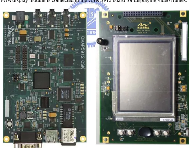
(11) 1.2. Introduction to the OMAP 5912 Starter Kit The Texas Instruments OMAP 5912 includes the MPU subsystem, the DSP subsystem, and the system direct memory access (SDMA). It is designed for multimedia applications, such as decoding of MPEG-4/H.263 video, MP3/AAC audio, and JPEG images. The MPU subsystem which performs most operation on the chip is based on the ARM926EJ. The DSP subsystem based on the TMS320C5510 is responsible for intensive data computing tasks. Both the MPU core and the DSP core have a maximal frequency at 192MHz. The OSK 5912 is a development board that integrated the OMAP 5912 chip and other peripherals such as 32MB DDR SDRAM, 32MB Flash ROM, an RS-232 serial port, and a 10Mbps Ethernet port, etc. Figure 1.1 shows the OSK 5912 development board and the Q-VGA display module. The Q-VGA display module is connected to the OSK 5912 board for displaying video frames.. Figure 1.1 - The OSK 5912 development board and Q-VGA display module.. 2.
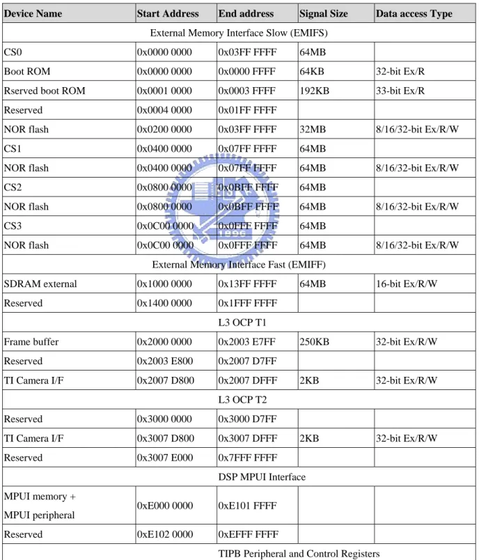
(12) 1.2.1. The Memory Map of OSK 5912 Table 1.1 shows the MPU global memory map. The DSP core has a 32KBx16-bit on-chip dual-access RAM (DARAM) and a 48KBx16-bit on-chip single access RAM (SARAM). Table 1.2 gives the DSP global memory map [5]. Note that the MPU core uses byte addressing while the DSP core uses word addressing. Device Name. Start Address. End address. Signal Size. Data access Type. External Memory Interface Slow (EMIFS) CS0. 0x0000 0000. 0x03FF FFFF. 64MB. Boot ROM. 0x0000 0000. 0x0000 FFFF. 64KB. 32-bit Ex/R. Rserved boot ROM. 0x0001 0000. 0x0003 FFFF. 192KB. 33-bit Ex/R. Reserved. 0x0004 0000. 0x01FF FFFF. NOR flash. 0x0200 0000. 0x03FF FFFF. 32MB. 8/16/32-bit Ex/R/W. CS1. 0x0400 0000. 0x07FF FFFF. 64MB. NOR flash. 0x0400 0000. 0x07FF FFFF. 64MB. CS2. 0x0800 0000. 0x0BFF FFFF. 64MB. NOR flash. 0x0800 0000. 0x0BFF FFFF. 64MB. CS3. 0x0C00 0000. 0x0FFF FFFF. 64MB. NOR flash. 0x0C00 0000. 0x0FFF FFFF. 64MB. 8/16/32-bit Ex/R/W. 8/16/32-bit Ex/R/W. 8/16/32-bit Ex/R/W. External Memory Interface Fast (EMIFF) SDRAM external. 0x1000 0000. 0x13FF FFFF. Reserved. 0x1400 0000. 0x1FFF FFFF. 64MB. 16-bit Ex/R/W. 250KB. 32-bit Ex/R/W. 2KB. 32-bit Ex/R/W. 2KB. 32-bit Ex/R/W. L3 OCP T1 Frame buffer. 0x2000 0000. 0x2003 E7FF. Reserved. 0x2003 E800. 0x2007 D7FF. TI Camera I/F. 0x2007 D800. 0x2007 DFFF L3 OCP T2. Reserved. 0x3000 0000. 0x3000 D7FF. TI Camera I/F. 0x3007 D800. 0x3007 DFFF. Reserved. 0x3007 E000. 0x7FFF FFFF DSP MPUI Interface. MPUI memory + MPUI peripheral Reserved. 0xE000 0000. 0xE101 FFFF. 0xE102 0000. 0xEFFF FFFF TIPB Peripheral and Control Registers. 3.
(13) Reserved. 0xF000 0000. 0xFFFA FFFF. OMAP5912 peripherals. 0xFFFB 0000. 0xFFFE FFFF. Reserved. 0xFFFF 0000. 0xFFFF FFFF. Table 1.1 - The MPU global memory map.. Byte address range. Word Address range. Internal memory. 0x00 0000 - 0x00 FFFF. 0x00 0000 - 0x00 7FFF. DARAM (64Kbytes). 0x01 0000 - 0x02 7FFF. 0x00 8000 - 0x01 3FFF. SARAM (96Kbytes). 0x02 8000 - 0x04 FFFF. 0x01 4000 - 0x02 7FFF. Reserved. 0x05 0000 - 0xFF 7FFF. 0x02 8000 - 0x7F 8FFF. 0xFF 8000 - 0xFF FFFF 0x7F C000 - 0x7F FFFF PDROM (MPNMC=0). External memory. Managed by DSP MMU Managed by DSP MMU (MPNMC=1). Table 1.2 - The DSP global memory map.. 1.2.2. Inter-processor communication on OMAP 5912 Three mechanisms are available for inter-processor communication (IPC) between the MPU and the DSP on the OMAP5912 device. These facilities include mailbox registers, the MPU Interface, and shared memory space. There are four sets of mailbox registers. Two of them are for the MPU core to send messages and issue interrupts to the DSP core, and the other two are for the DSP core to signals the MPU core. There are one 16-bit command register, one 16-bit data register, and one 1-bit flag register in each set of mailbox registers. When the command register is written, it causes an interrupt to the other processor and sets the responding flag register. The interrupted processor could read the command and data registers, and clear the flag. The second mechanism is the MPU interface (MPUI). MPUI enables the MPU core and the system DMA controller to access the memory-mapped registers of the DSP core and its peripherals such as the SARAM, the DARAM, and the control registers. The MPU/DSP shared memory via the traffic controller is the third mechanism for IPC. The MPU core and the DSP core could share accesses to the on-board SRAM and SDRAM if 4.
(14) the DSP memory management unit (MMU) is enabled and configured properly. We will give more details in section 4.2.2.. 1.3. Scope of the Thesis The rest of the thesis is organized as follows. Some previous work related to the design of the proposed streaming server with the dynamic task partition approach is introduced in chapter 2. Chapter 3 presents the architecture and details of the proposed streaming library. Chapter 4 describes the implement details of the dynamic task partition system in the streaming player. Chapter 5 shows the experimental results, and finally, the conclusion and some discussions will be given in chapter 6.. 5.
(15) Chapter 2.. Previous Work. In this chapter, we will review some previously published work related to the design of the proposed streaming player on a heterogeneous dual-core platform. The surveyed topics are as follows: task partitioning systems for multi-core architecture, implementations of RTP streaming protocols, and porting of the deeply-embedded OS eCos to the OMAP 5912 OSK.. 2.1. Static Task Partition Most heterogeneous multi-processor platforms apply static task partition decision at runtime. The designers profile and analyze an application during design time, and assign the sub-tasks of the application to each processor according to their behaviors. This assignment will not change during run-time even if the target processor core is busy with other tasks. Take the design in [6] as an example. Ye Yang et al. proposed the GEM-SOC architecture for portable media application, and used Ogg Voribs decoder [8] as an example to verify their proposed architecture. The Ogg Vorbis decoding task could be partitioned into decoding part and communication part. When user open the audio player, decoding module on the DSP core is loaded into on-chip memory by the RISC. The bitstream would be also loaded into the DSP on-chip memory before decoding every audio frame. The RISC core is only responsible for playing back after the DSP core finished decoding, and controlling the DSP decoding tasks. Kun-Yuan Hsieh et al. [7] presented a middleware called streaming remote procedure call (RPC) for a streaming-function remoting mechanism on heterogeneous dual-core architectures. They verified the streaming RPC both on an experimental platform known as the PAC dual-core platform and TI OMAP 5912 with a JPEG decoder, MP3 decoder, and QCIF H.264 decoder. The proposed streaming RPC is based on pCore Bridge [9] running on the MPU core, and pCore running on the DSP core. The pCore Bridge is a thread which provides basic communication modules, and the pCore cooperates well with the OS on the MPU. The paper 6.
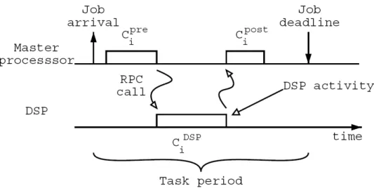
(16) took a MP3 decoder as an example, and the streaming RPC calls the DSP core to perform IMDCT through the pCore interface. The static task partition approach is commonly used in some researched and industry. However, the new generations of multimedia applications are more and more complex. Thus, we should consider other approaches for performance improvement.. 2.2. Dynamic Task Partition One of the disadvantage of static task partition is the program designer should profile and analyze the dual-core applications in advance, and then assign each task to the processor that is more capable of executing the task. This decision cannot change at run-time. Therefore, tasks would not be re-assigned to the other processor even if the originally assigned one is overloaded with other tasks. For example, the RISC is responsible only for task management while the computationally expensive tasks are always assigned to the DSP. The RISC might be idle and just waiting for the DSP to finish current job. Nowadays, the RISC processors are more powerful, and they could share the load of computation jobs for the DSP core. There are some researches for dynamic task partition as described in the following paragraphs. L. Sha et al. [11] proposed the Distributed Priority Ceiling Protocol (DPCP) for real-time synchronization on heterogeneous multiprocessor platforms in 1990. They assumed that the architecture is composed by a general purpose CPU and a DSP as a specialized CPU, and the two processor share a common bus, RAM memory, and some ROM (Flash) memory. The two processors and the shared resource are all built in the same chip. The general purpose CPU acts as the master processor, and the structure of a DSP task is shown in Figure 2.1. The tasks do not require a DSP activity are called regular tasks. Each DSP task executes CiDSP units of time, and pre-process and post- process take Cipre, Cipost units of time, respectively. For such real-time systems, the uncontrolled priority inversion problem, a high priority job is indirectly 7.
(17) blocked by lower priority jobs for an indefinite period of time, is solved by the proposed DPCP scheduling approach.. Figure 2.1 - Structure of a DSP task. Paolo Gai et al. [10] indicated the problem of DPCP. A hole is generated in the schedule of a master processor when executing a DSP task. In order to solve the problem, they re-arranged the scheduling and used a fixed priority assignment so that the master processor could execute other regular tasks when DSP is active. Two priority queues, one is for DSP tasks while the other is for regular tasks, are designed to the scheduling approach. When the DSP is idle, the scheduler selects the task with the highest priority in the two queues. When DSP is active, the scheduler only selects the task with the highest priority in the regular task queue. The improved DPCP achieves a significant improvement. The improvement in [10] still has some problems. Kwangsik Kim et al. [12] indicated that a regular task with lower priority may execute before a DSP task with higher priority. Also, if all the tasks are DSP tasks, the second task could not be executed in the hole time. Kim designed only one priority queue for DSP and regular tasks, thus another DSP task could be executed when DSP is active. Cheng-Nan Chiu et al. [13] proposed a dynamic dual-core partition framework for multimedia applications on heterogeneous dual-core platforms. In this paper, an MPEG-4 8.
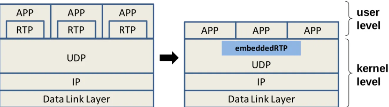
(18) simple profile encoder is used as an example to verify the proposed framework. They defined the task granularity at macroblock level, and the decoding tasks would be assigned dynamically to the processor with less loading. If both processors are available, the tasks would be dispatched to both of them for parallel execution. Even though [13] showed that the dynamic partitioning approach run faster than the conventional static task partition approach for the example video coding application, the communication overhead between processors was expensive since the task granularity was defined at macroblock level. Tsung-Fan Shen [14] designed a video decoder application based on the dynamic task partition approach. The inter-processor communication overhead is reduced by defining the task granularity at slice level. The experiments showed that the dual-core approach could easily fulfill real-time (30FPS) decoding of QVGA video at 96MHz and even out-perform the state-of-the-art implementation from the industry.. 2.3. RTP Streaming Libraries Streaming media is becoming popular on the Internet. At present, many streaming players support Real-time Transport Protocol (RTP), such as the QuickTime player, RealPlayer, and the VideoLAN VLC player. To maintain good quality streaming media presentations, there are many issues that should be taken into account. A good streaming library has to reduce the packet lost rate, enable high streaming data rate, and decrease the delay time. Many multimedia services such as VoD, AoD and VoIP adopted the RTP protocol for media transport, but the RTP library is typically not integrated into the network protocol stack of an operating system. Dong-Guk Sun et al. proposed the embeddedRTP architecture [32], which embed the RTP transport protocol into the network subsystem of the OS kernel so that it does not has to be include in every applications.. 9.
(19) APP. APP. APP. RTP. RTP. RTP. APP. APP. APP. user level. embeddedRTP. UDP. UDP. IP. IP. Data Link Layer. Data Link Layer. kernel level. Figure 2.2 – Protocol stack in normal case and embeddedRTP structure. As Figure 2.2 shows, they implemented the embeddedRTP at kernel level, and it could be invoked through system calls. Moreover, the embeddedRTP provides APIs for application portability. The experimental results from [32] show that the packet processing speed of embeddedRTP is about 7.8 times faster than UCL RTP [33] on a PDA device, and the memory requirement and code size are also less than UCL RTP. There are many streaming libraries in the open source community. For example, Nick Feamster et al. [16] designed an SR-RTP streaming library to adapt to variable bandwidth and delay, and perform selective retransmission for packet loss in their OxygenTV project. Arne Kepp [17] from Columbia University implemented jlibRTP for streaming media across IP-based networks, in Java. However, one of the most popular open source RTP libraries is the JRTPLIB developed by Jori Liesenborgs [18]. JRTPLIB is an object-oriented RTP library written in C++. The open source JRTBLIB is widely used in many industry and research projects, and the latest version of the library is 3.7.1. We will compare the performance of our proposed streaming library to that of the JRTPLIB later in Chapter 5 of this thesis.. 2.4. Porting of eCos Embedded Operating System to OMAP The OMAP 5912 OSK supports Monta Vista Linux 2.4, which uses a kernel module, DSP gateway, for IPC between the RISC core and the DSP core. Since the overhead of the DSP. 10.
(20) gateway is quite high, it is not suitable for the implementation of dynamic task partition system. In this thesis, we have selected the deeply-embedded OS, eCos, as the software implementation platform. The eCos is an open source, real-time operating system for embedded applications, and it is highly configurable so that the system could achieve best possible run-time performance. However, there is no official eCos port to OMAP 5912 OSK. Kuo-Cheng Lee [15] ported eCos to OMAP 5912 OSK, and designed efficient mailbox and shared memory communication mechanism for the study of an eCos-based dynamic task partition programming model for heterogeneous dual-core platforms. In the thesis, he designed a new dispatcher which is added to the eCos kernel for monitoring the run-time loading of each processor and dispatching tasks accordingly. Every task which is registered as a dual-core module would be assigned to either the MPU core or the DSP core dynamically at run-time based on the loading of both cores. Our streaming player application is based on the eCos port in [15].. 11.
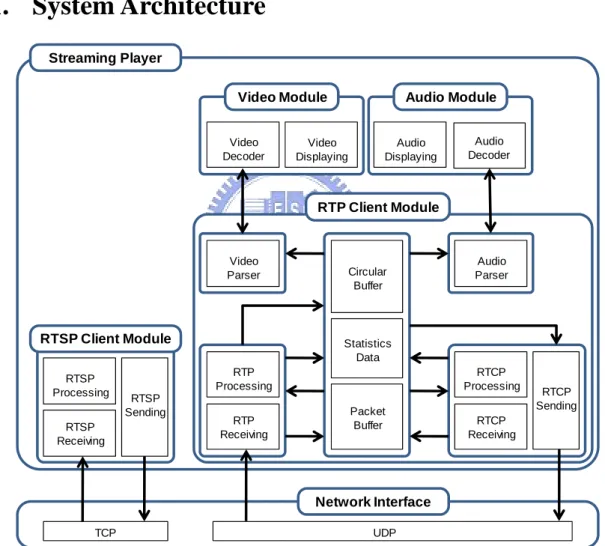
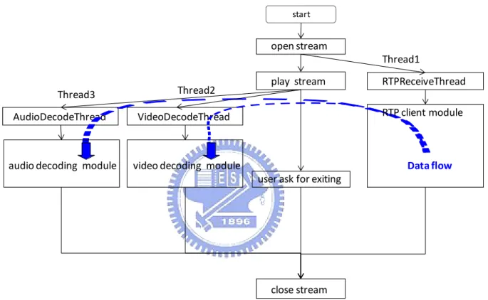
(21) Chapter 3.. Streaming Player Architecture. We give a detailed description of the proposed streaming player in this chapter. The overall system architecture is presented in section 3.1 first. Section 3.2 describes the RTSP client module, and section 3.3 introduces the RTP client module. The designs of the video and audio decoding modules are presented in section 3.4 and section 3.5, respectively.. 3.1. System Architecture Streaming Player Video Module Video Decoder. Audio Module. Video Displaying. Audio Displaying. Audio Decoder. RTP Client Module. Video Parser. RTSP Client Module RTSP Processing RTSP Receiving. Circular Buffer. Statistics Data RTP Processing. RTSP Sending. Audio Parser. RTP Receiving. RTCP Processing Packet Buffer. RTCP Sending. RTCP Receiving. Network Interface TCP. UDP. Figure 3.1 - The system architecture. Figure 3.1 shows the system architecture of the streaming player. The streaming player calls the RTSP module to connect to the streaming server, and creates an RTP receiving thread to receive the RTP and RTCP packets. Note that the RTP packets are transported over UDP while RTSP messages are transported over TCP. The receiving thread is created before the 12.
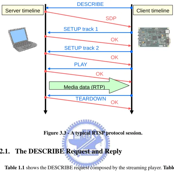
(22) player sends a RTSP PLAY request to the server in order to prevent potential packet losses at the beginning of a streaming session. After requesting the server to begin sending the audio and video contents, which are encapsulated in the RTP packets, the player creates the decoding threads to call payload parsers and decoders for media presentation. The player works until the user hitting the stop button and it would send a RTSP TEARDOWN message to the server to request for disconnection. Figure 3.2 shows the flowchart of the streaming player. . start. open stream Thread1 Thread2. Thread3 AudioDecodeThread. VideoDecodeThread. audio decoding module. video decoding module. play stream. RTPReceiveThread RTP client module. Data flow user ask for exiting. close stream. Figure 3.2 - The flow chart of the streaming player.. 3.2. RTSP Client Module This module communicates with the streaming server to establish a connection via the Real-Time Streaming Protocol (RTSP). A typical RTSP protocol transaction session is shown in. Figure 3.3.. 13.
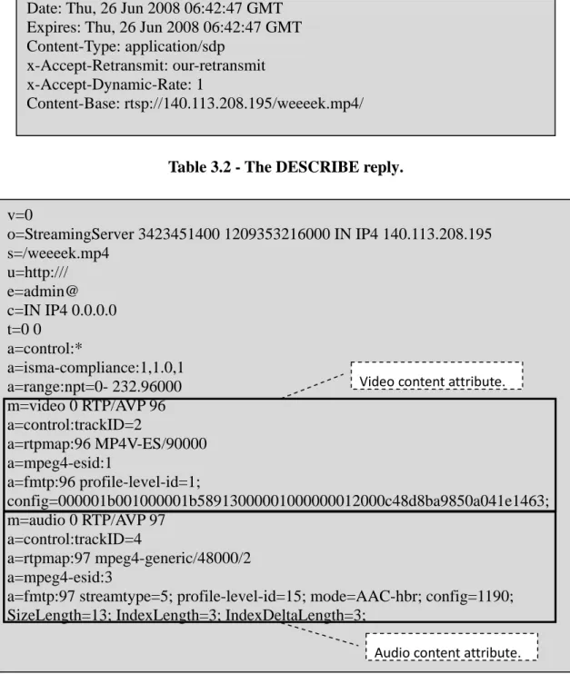
(23) DESCRIBE Server timeline. Client timeline SDP SETUP track 1 OK SETUP track 2 OK PLAY OK Media data (RTP) TEARDOWN. OK . Figure 3.3 - A typical RTSP protocol session.. 3.2.1. The DESCRIBE Request and Reply Table 1.1 shows the DESCRIBE request composed by the streaming player. Table 3.2 and Table 3.3 show the RTSP DESCRIBE reply. Table 3.2 is the DESCRIBE reply header while Table 3.3 is the entity body of the reply. The format of the entity body is coded in Session Description Protocol (SDP). We could derive the media attributes, such as number of tracks, content length, mime type, video header, and audio sample rate and so on, from the SDP content. For detail description of the protocol, please refer to RFC 2327 [4]. DESCRIBE rtsp://140.113.208.195/weeeek.mp4 RTSP/1.0 CSeq: 0 User-Agent: stream_player Accept: application/sdp Table 3.1 – The DESCRIBE request.. 14.
(24) RTSP/1.0 200 OK Server: DSS/5.5.5 (Build/489.16; Platform/Linux; Release/Darwin; state/beta; ) Cseq: 0 Last-Modified: Mon, 28 Apr 2008 03:26:56 GMT Cache-Control: must-revalidate Content-length: 1210 Date: Thu, 26 Jun 2008 06:42:47 GMT Expires: Thu, 26 Jun 2008 06:42:47 GMT Content-Type: application/sdp x-Accept-Retransmit: our-retransmit x-Accept-Dynamic-Rate: 1 Content-Base: rtsp://140.113.208.195/weeeek.mp4/. Table 3.2 - The DESCRIBE reply. v=0 o=StreamingServer 3423451400 1209353216000 IN IP4 140.113.208.195 s=/weeeek.mp4 u=http:/// e=admin@ c=IN IP4 0.0.0.0 t=0 0 a=control:* a=isma-compliance:1,1.0,1 Video content attribute. a=range:npt=0- 232.96000 m=video 0 RTP/AVP 96 a=control:trackID=2 a=rtpmap:96 MP4V-ES/90000 a=mpeg4-esid:1 a=fmtp:96 profile-level-id=1; config=000001b001000001b58913000001000000012000c48d8ba9850a041e1463; m=audio 0 RTP/AVP 97 a=control:trackID=4 a=rtpmap:97 mpeg4-generic/48000/2 a=mpeg4-esid:3 a=fmtp:97 streamtype=5; profile-level-id=15; mode=AAC-hbr; config=1190; SizeLength=13; IndexLength=3; IndexDeltaLength=3; Audio content attribute. . Table 3.3 - The SDP with MPEG-4 format content.. 15.
(25) 3.2.2.. The SETUP Request and Reply. The streaming player sends SETUP request for the tracks that the user wants to play. The information on client ports, server ports, SSRC and other attributes could be exchanged between the player and the server during this transaction. Table 3.4 is an example composed by the streaming player for requesting the contents with trackID equals to two, while Table 3.5 shows the corresponding reply. SETUP rtsp://140.113.208.195/weeeek.mp4/trackID=2 RTSP/1.0 CSeq: 1 Transport: RTP/AVP;unicast;client_port=6000-6001 Table 3.4 - The SETUP request. RTSP/1.0 200 OK Server: DSS/5.5.5 (Build/489.16; Platform/Linux; Release/Darwin; state/beta; ) Cseq: 1 Last-Modified: Mon, 28 Apr 2008 03:26:56 GMT Cache-Control: must-revalidate Session: 6696199755856328349 Date: Thu, 26 Jun 2008 06:42:47 GMT Expires: Thu, 26 Jun 2008 06:42:47 GMT Transport: RTP/AVP;unicast;source=140.113.208.195;client_port=6000-6001;server_port =6970-6971;ssrc=55191DF2. Table 3.5 - The SETUP reply.. 3.2.3. The PLAY Request and Reply The server sends the contents after receiving the PLAY request. Therefore, the player should be ready for receiving the incoming RTP packets as soon as it sends the PLAY request. The PLAY reply from the streaming server contains session information of each track. Table 3.6 and Table 3.7 show the PLAY request and its reply.. 16.
(26) PLAY rtsp://140.113.208.195/weeeek.mp4 RTSP/1.0 CSeq: 3 Session: 6696199755856328349 Range: npt=0Table 3.6 – The PLAY request. RTSP/1.0 200 OK Server: DSS/5.5.5 (Build/489.16; Platform/Linux; Release/Darwin; state/beta; ) Cseq: 3 Session: 6696199755856328349 Range: npt=0.00000-232.96000 RTP-Info: url=rtsp://140.113.208.195/weeeek.mp4/trackID=2;seq=3529;rtptime=534282 511,url=rtsp://140.113.208.195/weeeek.mp4/trackID=4;seq=35449;rtptime=11 8700607 Table 3.7 - The PLAY reply.. 3.2.4. The TEARDOWN Request and Reply The TEARDOWN request would be sent when the streaming player wants to end the RTP session. Table 3.8 and Table 3.9 show the TEARDOWN request and its reply. TEARDOWN rtsp://140.113.208.195/weeeek.mp4 RTSP/1.0 CSeq: 4 Session: 6696199755856328349Range: npt=0Table 3.8 - The TEARDOWN request. RTSP/1.0 200 OK Server: DSS/5.5.5 (Build/489.16; Platform/Linux; Release/Darwin; state/beta; ) Cseq: 3 Session: 1357751978789435963 Connection: Close Table 3.9 - The TEARDOWN reply.. 3.3. RTP Client Module This module is executed by the RTP receiving thread as soon as the RTSP client module. 17.
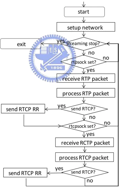
(27) sends a PLAY request. The network would be setup first and then the receiving thread enters a loop. In this loop, it checks whether the RTP and RTCP sockets is active. If the RTP socket is active, the RTP receiving module and the RTP processing module would be called to deal with the incoming RTP packets. The RTCP receiving and processing module would be called if the RTCP socket is active. After checking for an incoming RTP or RTCP packet, the RTCP Receiver Report (RR) module would be called if it is time to send an RTCP RR. Figure 3.4 shows the flowchart of the RTP client module. The following sections give the details of this modules and the design of the proposed efficient packet buffer sub-systems. . start setup network exit. yes streaming stop? no rtpsock set?. no. yes receive RTP packet process RTP packet send RTCP RR. yes send RTCP? no rtcpsock set?. no. yes receive RCTP packet process RTCP packet send RTCP RR. yes. send RTCP?. no Figure 3.4 - RTP client module flowchart.. 18.
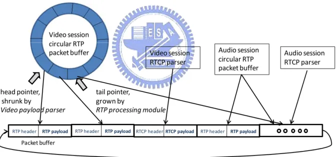
(28) 3.3.1. Buffer Design We designed a joint packet buffer pool for storing both the RTP and RTCP packets when the RTP or the RTCP receiving modules are invoked. All the arriving (audio and video) packets will be stored in this buffer sequentially. Once a packet enters the packet buffer, there is no need to copy it for de-multiplexing purpose until the decoders request its payload data. The audio and video circular buffers are data structures used to tag the packets in the joint packet buffer pool. Each element in the circular buffer stores the important header information such as the timestamp, the sequence number, and the mark bit, etc., and a pointer points to the location of its payload in the packet buffer pool. Figure 3.5 illustrates the relation between the circular buffer and the packet buffer pool.. Video session circular RTP packet buffer. head pointer, shrunk by Video payload parser RTP header. RTP payload. Video session RTCP parser. Audio session circular RTP packet buffer. Audio session RTCP parser. tail pointer, grown by RTP processing module RTP header. RTP payload RTCP header RTCP payload. RTP header. RTP payload. Packet buffer. Figure 3.5 - Relation between the circular buffer and joint the packet buffer pool. The buffers are large enough to accommodate 15 seconds of steaming media a bitrate of 6Mbps, and the maximal size of a UDP datagram is assumed to be 1514 bytes. Therefore, the player pre-allocates 7430 (= 6Mbps / (1514 *8 (bit/packet)) * 15sec) packet entries for the circular buffer data structure. To get around the issue of possible out-of-order delivery of UDP datagrams, the position of the RTP packets in the circular buffer is sorted according to the value of sequence number modulo the size of the circular buffer. We select the value that is a power of 19.
(29) two for this purpose. That is, in the program, we have the following parameter definition: #define RTP_CIRBUF_MAXSIZE. 8192. Because we need two circular buffers for audio and video tracks, the space required by the packet buffer should be greater than 2tracks * 8192 packets * 1514 bytes = 24805376 bytes. Hence, in the program, we have the following parameter definition: #define MAX_PACKET_BUF_SIZE. 25000000. 3.3.2. RTP Receiving Module The module is responsible for receiving an RTP packet, storing the packet into the packet buffer, and calling RTP processing module to validate and process this RTP packet. In the end, it calls RTCP sending module if it needs to send an RTCP RR... 3.3.3. RTP Processing Module This module processes an RTP packet with specified packet length and track identity. For each RTP packet, it validates SSRC field, skips padding bytes if the padding bit is set, and computes the jitter of the arriving RTP packets. The jitter is computed by the equations defined in RFC 3550 [3]. D(i,j) = (Rj-Sj)-(Ri,Si) Ji = Ji-1 + (|D(i,j)| - Ji-1) / 16 The RTP processing module first puts header information of the RTP packet into the circular buffer entry corresponds to the packet. This position of the entry is calculated using the RTP sequence number modulo the size of the circular buffer. It then changes the payload pointer in the circular buffer to point to the location of the RTP datagram in the packer buffer, updates the tail pointer and the network statistics of the streaming session. Table 3.10 shows the structure of an RTP packet, please see RFC 3550 [3] for the details of each field. 20.
(30) 0. 1 2 3 0 1 2 3 4 5 6 7 8 9 0 1 2 3 4 5 6 7 8 9 0 1 2 3 4 5 6 7 8 9 0 1 +-+-+-+-+-+-+-+-+-+-+-+-+-+-+-+-+-+-+-+-+-+-+-+-+-+-+-+-+-+-+-+-+ |V=2|P|X| CC |M| PT | sequence number | +-+-+-+-+-+-+-+-+-+-+-+-+-+-+-+-+-+-+-+-+-+-+-+-+-+-+-+-+-+-+-+-+ | timestamp | +-+-+-+-+-+-+-+-+-+-+-+-+-+-+-+-+-+-+-+-+-+-+-+-+-+-+-+-+-+-+-+-+ | synchronization source (SSRC) identifier | +=+=+=+=+=+=+=+=+=+=+=+=+=+=+=+=+=+=+=+=+=+=+=+=+=+=+=+=+=+=+=+=+ | payload | | .... | +-+-+-+-+-+-+-+-+-+-+-+-+-+-+-+-+-+-+-+-+-+-+-+-+-+-+-+-+-+-+-+-+. Table 3.10 - RTP packet format.. 3.3.4. RTCP Receiving Module The module is responsible for receiving an RTCP Sender Report (SR) packet, storing the packet in the packet buffer, and calling RTCP processing module to validate and process this RTCP SR packet. In the end, it calls RTCP sending module to send RTCP RR if necessary.. 3.3.5. RTCP Processing Module This module processes an RTCP sender report (SR) packet with specified packet length and track identity. For each RTCP packet, it validates the SR header, SDES header, and updates the network statistics of the streaming session. If the RTCP BYE packet is appended, we know that the server has ended the streaming session. Table 3.11 shows the structure of the RTCP SR packet, please see RFC 3550 [3] for the details of each field.. 21.
(31) . 0 1 2 3 0 1 2 3 4 5 6 7 8 9 0 1 2 3 4 5 6 7 8 9 0 1 2 3 4 5 6 7 8 9 0 1 +-+-+-+-+-+-+-+-+-+-+-+-+-+-+-+-+-+-+-+-+-+-+-+-+-+-+-+-+-+-+-+-+ |V=2|P| RC | PT=SR=200 | length | header +-+-+-+-+-+-+-+-+-+-+-+-+-+-+-+-+-+-+-+-+-+-+-+-+-+-+-+-+-+-+-+-+ | SSRC of sender | +=+=+=+=+=+=+=+=+=+=+=+=+=+=+=+=+=+=+=+=+=+=+=+=+=+=+=+=+=+=+=+=+ | NTP timestamp, most significant word | sender +-+-+-+-+-+-+-+-+-+-+-+-+-+-+-+-+-+-+-+-+-+-+-+-+-+-+-+-+-+-+-+-+ info | NTP timestamp, least significant word | +-+-+-+-+-+-+-+-+-+-+-+-+-+-+-+-+-+-+-+-+-+-+-+-+-+-+-+-+-+-+-+-+ | RTP timestamp | +-+-+-+-+-+-+-+-+-+-+-+-+-+-+-+-+-+-+-+-+-+-+-+-+-+-+-+-+-+-+-+-+ | sender's packet count | +-+-+-+-+-+-+-+-+-+-+-+-+-+-+-+-+-+-+-+-+-+-+-+-+-+-+-+-+-+-+-+-+ | sender's octet count | +=+=+=+=+=+=+=+=+=+=+=+=+=+=+=+=+=+=+=+=+=+=+=+=+=+=+=+=+=+=+=+=+ |V=2|P| SC | PT=SDES=202 | length | sdes +-+-+-+-+-+-+-+-+-+-+-+-+-+-+-+-+-+-+-+-+-+-+-+-+-+-+-+-+-+-+-+-+ | SSRC | +=+=+=+=+=+=+=+=+=+=+=+=+=+=+=+=+=+=+=+=+=+=+=+=+=+=+=+=+=+=+=+=+ | CNAME=1 | length | user and domain name ... +=+=+=+=+=+=+=+=+=+=+=+=+=+=+=+=+=+=+=+=+=+=+=+=+=+=+=+=+=+=+=+=+ |V=2|P| SC | PT=BYE=203 | length | bye +-+-+-+-+-+-+-+-+-+-+-+-+-+-+-+-+-+-+-+-+-+-+-+-+-+-+-+-+-+-+-+-+ | SSRC | +=+=+=+=+=+=+=+=+=+=+=+=+=+=+=+=+=+=+=+=+=+=+=+=+=+=+=+=+=+=+=+=+. Table 3.11 - RTCP SR packet format.. 3.3.6. RTCP Sending Module The module generates RTCP RR for the RTP session. Table 3.12 shows the structure of the RTCP RR packet, the details of each field are defined in RFC 3550 [3]. The BYE block would be appended if the user exits the connection.. 22.
(32) . 0 1 2 3 0 1 2 3 4 5 6 7 8 9 0 1 2 3 4 5 6 7 8 9 0 1 2 3 4 5 6 7 8 9 0 1 +-+-+-+-+-+-+-+-+-+-+-+-+-+-+-+-+-+-+-+-+-+-+-+-+-+-+-+-+-+-+-+-+ |V=2|P| RC | PT=RR=201 | length | header +-+-+-+-+-+-+-+-+-+-+-+-+-+-+-+-+-+-+-+-+-+-+-+-+-+-+-+-+-+-+-+-+ | SSRC of packet sender | +=+=+=+=+=+=+=+=+=+=+=+=+=+=+=+=+=+=+=+=+=+=+=+=+=+=+=+=+=+=+=+=+ | SSRC | receiver +-+-+-+-+-+-+-+-+-+-+-+-+-+-+-+-+-+-+-+-+-+-+-+-+-+-+-+-+-+-+-+-+ report | fraction lost | cumulative number of packets lost | +-+-+-+-+-+-+-+-+-+-+-+-+-+-+-+-+-+-+-+-+-+-+-+-+-+-+-+-+-+-+-+-+ | extended highest sequence number received | +-+-+-+-+-+-+-+-+-+-+-+-+-+-+-+-+-+-+-+-+-+-+-+-+-+-+-+-+-+-+-+-+ | interarrival jitter | +-+-+-+-+-+-+-+-+-+-+-+-+-+-+-+-+-+-+-+-+-+-+-+-+-+-+-+-+-+-+-+-+ | last SR (LSR) | +-+-+-+-+-+-+-+-+-+-+-+-+-+-+-+-+-+-+-+-+-+-+-+-+-+-+-+-+-+-+-+-+ | delay since last SR (DLSR) | +=+=+=+=+=+=+=+=+=+=+=+=+=+=+=+=+=+=+=+=+=+=+=+=+=+=+=+=+=+=+=+=+ |V=2|P| SC | PT=SDES=202 | length | sdes +-+-+-+-+-+-+-+-+-+-+-+-+-+-+-+-+-+-+-+-+-+-+-+-+-+-+-+-+-+-+-+-+ | SSRC | +=+=+=+=+=+=+=+=+=+=+=+=+=+=+=+=+=+=+=+=+=+=+=+=+=+=+=+=+=+=+=+=+ | CNAME=1 | length | user and domain name ... +=+=+=+=+=+=+=+=+=+=+=+=+=+=+=+=+=+=+=+=+=+=+=+=+=+=+=+=+=+=+=+=+ |V=2|P| SC | PT=BYE=203 | length | bye +-+-+-+-+-+-+-+-+-+-+-+-+-+-+-+-+-+-+-+-+-+-+-+-+-+-+-+-+-+-+-+-+ | SSRC | +=+=+=+=+=+=+=+=+=+=+=+=+=+=+=+=+=+=+=+=+=+=+=+=+=+=+=+=+=+=+=+=+. Table 3.12 - The RTCP RR.. 3.3.7. Video Payload Parser The video parser returns the next video frame and its length and timestamp for given video track. If the remaining contents in circular buffer are too few to play, it enters re-buffering mode to wait until there are enough contents for continuous playback (i.e., waiting for the tail pointer to grow beyond a point). Figure 3.6 illustrates the operation of the circular buffer.. 23.
(33) . head pointer, shrunk by Video payload parser Circular RTP packet buffer. tail pointer, grown by RTP processing module. Figure 3.6 - The operation of the circular buffer. The RTP packets whose payloads belong to the same video frame have the same timestamp. The video payload parser would copy the RTP payloads to the video buffer until the marker bit is equal to one. Figure 3.7 illustrates the payload parser operation and the relation between the circular buffer, the packet buffer and the video buffer. Note that the payload parsers are designed to implement subsets of the media payload RFCs that correspond to the implementation of the open source Darwin Streaming Server. . Circular buffer 0. Payload pointer. 0. Payload pointer. 1. Payload pointer. Packet buffer RTP header. RTP payload. RTP header. RTP payload. RTP payload. RTP payload. RTP header. RTP payload. RTP payload. Video buffer. Figure 3.7 - The payload parser operation.. 3.3.8. Audio Payload Parser The audio payload parser returns the next audio frame and its length and timestamp for given audio track. It works in the same way as the video payload parser. Please see 3.3.7 for the details.. 24.
(34) 3.4. Video Decoding Module This module is called by the video decoding thread with track ID as the input parameter and is responsible for video decoding and displaying. For each frame, it calls the video payload parser in the RTP client module to get a video frame and passes the frame to the MPEG-4 video decoder. The module also calls display module to convert a frame represented in YCBCR 4:2:0 color format to the RGB format and stores the frame data in video frame buffer for display. Figure 3.8 shows the flow chart of the video decoding module.. start get video header decode video header setup for displaying no. thread running? yes get video sample decode frame display exit. Figure 3.8 - Video decoding module flowchart.. 3.5. Audio Decoding Module This module is called by audio decoding thread with track ID as the input parameter and is responsible for audio decoding and playback. It calls the audio payload parser in 25.
(35) the RTP client module to get an audio frame. For each audio frame, it passes the contents to the AAC decoder and sends a raw signed 16-bit PCM data to the audio device for playback (for implementation under Linux, it uses the OSS API). It is important to point out that the player does not use sophisticated ping-pong buffer management for audio playback (which requires low-level audio APIs such as the Linux ALSA audio API). Therefore, there may be some clicking noise during audio playback. However, this issue does not affect the verification of the streaming library and functional behavior of the streaming player. Currently, this module is only implemented under Linux. The OS we adopt in this thesis is eCos, and we focus only on dynamic task partition for the MPEG-4 video decoding process. Therefore, we did not implement the audio decoding module under eCos. . 26.
(36) Chapter 4.. Dynamic Partition Architecture. The proposed streaming player in this thesis adopts a dynamic task partition approach for video decoding. Video decoding tasks are divided into slice decoding subtasks, where each subtask is dispatched to the RISC core or the DSP core for processing based on the run-time loading of each core. The dynamic task partition MPEG-4 video decoder by Tsung-Fan Shen [14] is used as the starting point of our implementation. The decoder described in [14] is a barebone video decoder that is not integrated into a complete multimedia system. In this chapter, the detail of integrating the video decoder into a complete streaming player running under eCos is presented.. 4.1. System Overview The dynamic task partition approach video decoder was originally developed [14] using Code Composer Studio (CCS) by Texas Instruments. The decoder is loaded via a JTAG cable from CCS onto the OSK 5912 for execution. The decoder reads the video bitstream from on-board flash memory, decodes the bitstream, and writes the output to the video frame buffer. However, for a standalone streaming player, it is easier to use an OS with network stack implementation. eCos is selected as the base operating system in this thesis. Although OSK 5912 comes with MontaVista Linux, it is too heavy for embedded streaming applications. Also, the DSP Gateway module used for IPC under Linux is not efficient enough for dynamic task partitioning. Hence we use the eCos ported by Kuo-Cheng Lee [15]. To make a standalone streaming player under eCos, the DSP codes must be loaded and initiated by the RISC processor. We follow the steps shown in Figure 4.1. First, develop the DSP codes by CCS and generate an executable file (with suffix “.out”). Be sure that the memory is assigned properly and the .text section should include the DSP boot codes. Since the DSP codes are loaded by the RISC, the memory used to hold DSP codes should be accessible 27.
(37) by the RISC core. We convert the .out file generated by CCS to a hexadecimal header file by the out2boot tool [19]. Note that we have modified the out2boot to match the organization of the DSP memory map of the streaming player. The RISC code that boots the DSP must include the dsp_proj_code.h generated during previous step, which contains the binary of the DSP code. Finally, the RISC codes (including eCos kernel, DSP boot code, and the streaming player application) is compiled into a single executable .elf file. The RISC core sets the corresponding DSP control registers and initializes the DSP MMU (memory map unit). Upon startup, the RISC core loads the DSP codes defined in a byte array in dsp_proj_code.h into the proper SDRAM addresses. After that, it enables the DSP MMU and DSP control registers. If the DSP core is enabled, it would set the mailbox to inform the RISC core for next step. The RISC core starts to communicate with the streaming server and create a receiving thread for the incoming RTP packets. The video decoding control thread is also executed by the RISC core, and it starts dispatching decoding and displaying tasks to the DSP core through mailbox if the DSP core is not busy. Otherwise it will handle the next decoding task by itself.. 28.
(38) RISC core. DSP core Compile DSP codes under CCS to generate executable .out file Convert .out to RISC readable hexadecimal .h file. Include dsp_proj_code.h. Compile time. Set DSP MMU and corresponding register Compile ARM codes under eCos to generate executable .elf file. Load DSP codes into SDRAM Enable DSP MMU and DSP core DSP is ready Receive RTP packets and decode. Run time. Decode and display Communicate via mailbox. Figure 4.1 - System development flowchart.. 4.2.. System organization on the DSP side. This section describes the details of the executable .out file format, the MPU readable hexadecimal header file, the out2boot converting tool, and the DSP MMU and DSP control registers.. 4.2.1. DSP Executable File Conversion The DSP codes are developed using CCS, generate an executable .out file. The .out file is loaded through the JTAG interface for bootstrapping the DSP. For a standalone embedded. 29.
(39) system, we could not use the JTAG interface to boot the system after the developing time. Therefore, the SDRAM booting mode is provided by the DSP. Rishi Bhattacharya provided a DSP booting example on OMAP 5910 [19]. The DSP executable .out file is converted into a const data array in a header file and compiled with the RISC codes. After the const data array is loaded into SARAM through the MPUI, the DSP could be enabled by the RISC. The flowchart of this DSP booting example is shown in Figure 4.2 - Bootloader build flowchart. DSP project files. Project build. dsp_proj.out. Run OUT2BOOT on dsp_proj.out. dsp_proj_code.h. ARM project files. Project build. arm_boot.out. Figure 4.2 - Bootloader build flowchart. The converting tool, out2boot, is also provided in [19]. It calls the Hex Conversion Utility (hex55.exe) which is provided by CCS [20] to convert the .out file into an Intel MCS-86 object format and then converts to a const data array in a header file which calls dsp_proj_code.h. The Intel MCS-86 object format is shown in Table 4.1.. 30.
(40) Address Start Character. Most Significant Check 16 Bits Sum. Check Sum. :020000040008F2 :20000000EC314E00330078300002F406F91F98F506410098F496FA0098F5968000984656BF :200020004617EC318E003B009089908A908B908C908D908E908F908790866C08EC286C0890 :200040008EA03C196C08E9B4ED310800D52EEB310800D52CF7310001003B67ED318F00D571 Byte Recode Count Type. Data. Table 4.1 - Intel MCS-86 object format. Only 16 bits address could be recoded in the MCS-86 format, but 32 bits address is needed on the RISC side. Thus, we must assign the higher 16 bits of the address in out2boot. On the other hand, we select the external memory booting mode from 0x080000 by set the DSP_BOOT_CONFIG register equal to one. The CCS linker file (.cmd file) should be also applied to this booting mode. The .cmd file configuration is shown in Table 4.2. The .text section should include boot.obj to initialize the DSP system by executing c_int00 function and then enter main function. MEMORY { … DARAM: ... SARAM: … SDRAM_Text: …. origin = 0x5A00,. len = 0x1A600. origin = 0x21A00,. len=0x3570. origin = 0x080000,. len = 0x20000. } SECTIONS { … .text: …. { rts55x.lib<boot.obj> (.text) } > SDRAM_Text. }. Table 4.2 - Linker file configuration. Since the DSP program for the streaming player uses DARAM and SDRAM, the Recode Type in Intel MCS-86 object would be equal to four, and the type is not supported by out2boot. We modified the out2boot program in order to support the intended DSP memory map of the streaming player. 31.
(41) 4.2.2. DSP Memory Management Unit Five boot modes are provided for the DSP bootloader. The MPU could select any of these boot modes by setting the DSP_BOOT_CONFIG register [21]. Our system writes the DSP_BOOT_CONFIG register to one to boot DSP from external memory (SDRAM). The bootloader simply branches to byte address 0x08 0000 in DSP external memory after enabling the DSP. The MPU core needs to set up the DSP MMU such that the DSP core executes from valid DSP external memory for this boot mode. Table 4.3 describes the memory map of our streaming player. The DSP codes which are specified in DARAM and SARAM could be loaded to the corresponding 32-bit address through the MPUI. As for the .text section, the MPU core loads the codes to the corresponding 32-bit SDRAM address and enables the DSP MMU so that the DSP can fetch instruction codes from this memory area. MPU (32 bits address). DSP (16 bits address). 0xE0000000-0xE000FFFF. 0x000000-0x00FFFF. DARAM. 0xE0010000-0xE0028000. 0x010000-0x028000. SARAM. 0x080000-0x09FFFF. SDRAM. 0x10000000-0x101FFFFF. eCos system memory. 0x10280000-0x1029FFFF. .text section 0x10300000-0x103FFFFF. 0x500000-0x5FFFFF. Bitstream. 0x10400000-0x104FFFFF. 0x600000-0x6FFFFF. Frame buffer. 0x10500000-0x105FFFFF. 0x700000-0x7FFFFF. Current decoded YUV frame. 0x10600000-. eCos system memory. Table 4.3 - The streaming player memory map. The DSP MMU could translate 24-bit DSP virtual address to 32-bit MPU physical address by using the translation look-aside buffer (TLB) contained in the MMU. The TLB contains CAM and RAM embedded memories. Each entry in the CAM stores the virtual tag, the preserved bits, valid bits, and page size. In the RAM, each entry contains the upper part of the 32.
(42) corresponding physical address and the access protection field. We define the page size of each mapping to section (1Mbytes). The address translation for section page size is shown in Figure 4.3. 24-bit DSP Virtual Address 23. 20 19. 0. table Index. section Index. CAM ‐ table index 31. 20 19. section base index. 12 11 10 9. 0. AP. 12 31. 20 19. section base index. 20. 0. section index. 32-bit Physical Address. Figure 4.3 - The address translation.. 4.3.. Design of Dynamic Task Partition Mechanism. Nowadays, an application targeted for the execution on heterogeneous multi-core platforms usually adopts static partition where task partition is done at development time. The dynamic partition where task partition is done at run-time according to the loading of each core at run time is mostly for symmetric multi-core systems. New generations of RISC processors are powerful enough to take over some of the computationally expensive jobs. Besides, multimedia applications like streaming player might become more complicated and could not reach optimal performance if static task partition is used. For mobile devices, the streaming data rates are usually not high enough such that the streaming player only receives streaming packets periodically from the server. This application scenario makes the RISC core be idling most of the time while the DSP might be busy decoding all media data received. Therefore, dynamic task partition is used in this thesis so that the task could be dispatched to the idling core 33.
(43) during runtime and makes the system reach the optimal performance.. 4.3.1.. Design Issues for Dual-core Application. There are some issues in the heterogeneous dual-core platforms that hinder the performance of dynamic task partition. First, the data accessing unit size of the DSP and MPU core are different on OMAP 5912. The 32-bit MPU core allows byte addressing while the 16-bit DSP allows only 16-bit word addressing. Thus, we use the same optimal data accessing unit size for optimal performance. Besides, the MPU uses the little-endian data format while the DSP operates in big-endian mode. The endian issue should be concerned when loading the DSP codes to the SARAM, DARAM or SDRAM and the bitstream sharing by the MPU and DSP.. 4.3.2. System memory map We use the advantages of memory bank to improve the performance. Since the DSP core has two on-chip memory blocks, 64KB DARAM and 96KB SARAM, the frequently accessed data should be put into them due to higher memory bandwidth. For example, the .stack, .sysstack and .bss section that store parameters and variables are accessed frequently. Hence, we assigned these sections to the DARAM. On the other hand, the Internal Reference Macroblock Buffer (IRMB) which contains some macroblock data of previously decoded frame are also allocated in the DARAM due to the fact that the macroblocks might be accessed many times when decoding current frame. The Internal Current Macroblock Buffer (ICMB) which stores currently decoded macroblock YCBCR data is located inside SARAM for speeding up the accesses. Due to the size limit of internal memory, some data that would not be accessed frequently should be assigned to the external memory. The .text section, input bitstream, current decoding frame and reference frame are allocated to SDRAM. Figure 4.4 shows the global memory map of the dynamic partition streaming player. 34.
(44) Memory map on ARM. Memory map on DSP 0×00 0000. DARAM(64KB). 0×01 0000 Code section. MPUI. SDRAM (32MB) Input bitstream. Data section (stack,.sysstack,.bss) IRMB. SARAM(96KB) IMGLIB Buf f er. 0×1028 0000. Current f rame. 0×1030 0000. Ref erence f rame. 0×1040 0000. Data section (.cinit, .cio, .const, .switch). 0×1050 0000. Internal Bitstream Buf f er (IBB). Code section Data section. ICMB QVGA Frame buf f er Clipping table Macroblock Inf o. 0×E000 0000 0×E001 0000. 0×08 0000. DSP MMU. 0×28 0000. : DSP access only. 0×30 0000. : ARM access only. 0×38 0000. : Both ARM / DSP access. Figure 4.4 - The global memory diagram.. 4.3.3.. Dual-core Video Decoding Architecture. Since we proposed a dynamic task partition approach for video decoding, the task granularity should be carefully designed. If the task granularity is too small, the communication overhead between two cores would restrict the performance. On the other hand, the computation model would operate like static task partition if the task granularity is too large. Therefore, we define task granularity at slice level. One video frame would be encoded into several slices, and there is no dependency between two slices. Five slices per frame is used for experiments in this thesis (for video resolution of 320x240), but the implementation is not tied to any particular slice number per frame. A system control module running on the MPU core is called Task Partitioner, and it is combined with the video decoding module described in 3.4 and responsible for dynamic task assignment. The DSP core executes the Task Interface module to receive the tasks assigned via mailbox commands from the Task Partitioner. Figure 4.5 shows the dynamic video decoding 35.
(45) task partition flow. The following subsections will describe details of the control flags and the mailbox commands. 0x10280000 Task Partitioner. 0x080000 A2D mailbox ISR. D2A mailbox ISR. Task Interface. 0x10300000. get next frame A2D_INITIALIZE_DECODER. initialize DSP decoder. 0x500000. initialize ARM decoder D2A_INITIALIZE_DONE 0. 0x10300000 0x10500000 (cury) 0x10540000 (curu) 0x10550000 (curv) 0x10560000 (refy) 0x105A0000 (refy) 0x105B0000 (refy). dsp_dec_initialized?. dsp_dec_initialized=1. 1 0. video_thread_running? 1 A2D_PARSE_SLICE. DSP parse frame. ARM parse frame. FRAME_NOT_FINISHED?. D2A_PARSING_DONE. 0. DSP_SLICE_NUM=4?. 0. 1. 1. FRAME_NOT_FINISHED=0. count ARM_SLICE_NUM 0. 0. ARM_SLICE_NUM<5?. FRAME_NOT_FINISHED? 1. 1. 0. 0x500000 0x700000 (cury) 0x740000 (curu) 0x750000 (curv) 0x760000 (refy) 0x7A0000 (refy) 0x7B0000 (refy). ARM decode slice. count DSP_SLICE_NUM. ARM_SLICE_NUM=4?. DSP_SLICE_NUM<5?. 0. 1. 1. A2D_DECODE_SLICE. FRAME_NOT_FINISHED=0. decode_slice_flag=1. decode_slice_flag=1?. 0. 1 DSP decode slice D2A_DECODING_DONE 1. FRAME_NOT_FINISHED? 0 A2D_DISPLAY display_flag=1. 0x600000. 0. display_flag=1?. 0. 1 display frame D2A_DISPLAYING_DONE. dsp_display_ok=1? 1 get next frame. dsp_display_ok=1. 0x10300000. return. Figure 4.5 - The dynamic video decoding task partition flow. 36.
(46) 4.3.3.1. Control Variables for Dynamic Task Partition Four important control variables are introduced in this subsection. ¾. VIDEO_THREAD_RUNNING The flag is set by the streaming player main program. It would be set to 0 if video. decoding thread has to exit. ¾. ARM_SLICE_NUM. ¾. DSP_SLICE_NUM The two variables indicate the slice number of a video frame that the MPU and DSP. core should decode. They are calculated as follows:. ARM_SLICE_NUM = MAX (ARM_SLICE_NUM, DSP_SLICE_NUM) +1 ¾. FRAME_NOT_FINISHED This flag would be set to 0 if the ARM_SLICE_NUM or DSP_SLICE_NUM is equal. to four, and that means all slices of the current frame has been decoded. The Task Partitioner could initialize the next frame decoding if the FRAME_NOT_FINISHED is set to one.. 4.3.3.2. Mailbox Commands Both the Task Partitioner and Task Interface have mailbox interrupt service routines (ISRs) associated with them for receiving commands and notifications from the other core. After the MPU core enables the DSP core, the DSP core would send a D2A_READY command to inform the Task Partitioner that the DSP is ready for job assignment. The Task Partitioner then sends an A2D_INITIALIZE_DECODER command to initialize the decoder on the DSP side. At the same time, the Task Partitioner calls MPU decoder initialization function to initialize the video decoder module on the MPU side. As soon as the Task Partitioner receives 37.
(47) D2A_INITIALIZATION_DONE command, it sends A2D_PARSE_SLICE command and then calls the MPU video decoding module for parsing slices of current frame. The dispatch of the slice decoding task is done according to the ARM_SLICE_NUM and DSP_SLICE_NUM variables introduced in previous subsection. The Task Partitioner sends a A2D_DECODE_SLICE command with DSP_SLICE_NUM as the parameter to ask the DSP core to decode the corresponding slice. The Task Partitioner would not dispatch next slice decoding. task. to. the. DSP. core. until. the. Task. Interface. send. a. D2A_DECODING_SLICE_DONE notification. If all slices in a frame are decoded, the Task Partitioner sends an A2D_DISPLAY command to the DSP core for color conversion and displaying. After the D2A_DISPLAYING_DONE command is received, the MPU video decoding module calls video payload parser to get next video frame and enter next decoding iteration. The Task Partitioner sends an A2D_RELEASE_DECODER command, waits for D2A_RELEASING_DECODER command from the Task Interface. Similar synchronization techniques is used in the MPU video decoding module for releasing the MPU and DSP decoder if VIDEO_THREAD_RUNNING flag is set to zero. The mailbox command transaction flowchart is shown in Figure 4.6.. 38.
(48) Task Interface. Task Partitioner D2A_READY A2D_INITIALIZE_DEOCDER. D2A_INITIALIZATION_DONE A2D_PARES_SLICE D2A_PARSING_DONE A2D_DECODE_SLICE. Decoding a slice. D2A_DECODING_SLICE_DONE. Decoding a slice. … A2D_DECODE_SLICE D2A_DECODING_SLICE_DONE. …. A2D_DISPLAY. D2A_DISPLAYING_DONE. Finish. A2D_Release_DECODER D2A_RELEASING_DONE. Figure 4.6 - The mailbox command transaction flowchart.. 39.
(49) Chapter 5.. Experimental Results. This chapter shows experimental results of our streaming player. Two development boards are used during the experiments. First, to evaluate the performance of the proposed RTP streaming module, a Xilinx ML403 board is used to compare the proposed RTP streaming library against the popular JRTP library. The reason we use ML403 instead of OSK 5912 for the first set of experiments is because the eCos Ethernet controller driver on 5912 OSK only allow streaming at a fairly low data rate. Therefore, it is difficult to discriminate those two streaming libraries on OSK 5912. However, since ML403 also has a RISC processor (PowerPC 405), the performance comparisons on ML403 should be able to reflect the behaviors of both libraries on typical embedded systems. For the second set of experiments that test the performance of the dynamic task partition system, the OSK 5912 is used, as described in previous chapters. For the second set of the experiments, we set the clock rate of both MPU and DSP core to 96MHz.. 5.1. Experiments on Streaming Library Performance Since Ethernet controller under eCos is not efficient enough, we test our streaming library on a PowerPC-based embedded platform, the Xilinx ML403 board. The processor clock rate is 300MHz, and it uses the MontaVista Linux Professional Edition 3.1 based on the 2.4 Linux kernel. An USB Ethernet dongle is used for the streaming stress tests because the on board Ethernet PHY and network driver implementation seems to have trouble with back-to-back delivered packets. Therefore, even if the content bit rate is low, many packets will get lost unless the simulated server performs traffic shaping. On the other hand, the USB Ethernet dongle has much better support on ML403 and it is quite stable for moderately high data rate. Hence, we use the USB Ethernet PHY to test our streaming library. We test our streaming library and compare the performance to that of the the open source 40.
(50) library JRTPLIB 3.7.1 developed by Jori Liesenborgs [18]. The content bit rates used in the tests range from 1Mbps to 7Mbps with one video track and one audio track. The streaming player creates only one thread to receive both RTP and RTCP packets. Also, to simulate video and audio decoding behavior, the streaming player creates one or two more busy threads. Note that the RTCP RR sending module is disabled for our tests. The test cases are described as follows: ¾. A1 : One RTP receiving thread based on JRTPLIB. ¾. B1: One RTP receiving thread based on the proposed streaming library. ¾. A2: One RTP receiving thread based on JRTPLIB, and one busy thread. ¾. B2: One RTP receiving thread based on the proposed streaming library, and one busy thread. ¾. A3: One RTP receiving thread based on JRTPLIB, and two busy threads. ¾. B3: One RTP receiving thread based on the proposed streaming library, and two busy threads. 41.
(51) 100% 90% 80%. packet lost rate (%). 70% 60% 50% 40% 30% 20% 10% 0% A1. 1Mbps. 2Mbps. 3Mbps. 4Mbps. 5Mbps. 6Mbps. 7Mbps. 0%. 0%. 0%. 0.01%. 0.03%. 5.51%. 18.69% 18.76%. B1. 0%. 0%. 0%. 0%. 0.03%. 5.53%. A2. 0.05%. 0.26%. 4.69%. 14.26%. 20.65%. 28.35%. 38.30%. B2. 0%. 0%. 0%. 0%. 0.02%. 5.51%. 18.71%. A3. 0.44%. 20.59%. 35.12%. 43.64%. 47.59%. 52.69%. 59.23%. B3. 0%. 0.55%. 0.11%. 0%. 0.19%. 5.78%. 19.55%. Figure 5.1 - The RTPLIB and the proposed streaming library performance comparisons. Figure 5.1 shows the packet lost rate under three different conditions. A1 and A2 have similar packet lost rates because the RTP receiving thread has enough CPU resource. The packet lost rate increases when the data rate higher than 5Mbps is transmitted due to the limitation of the USB Ethernet dongle. The performances of test cases A2 and A3 are bad while the performances of test cases B2 and B3 are still as good as B1. These experiments demonstrates that the proposed streaming library requires much lower CPU resources and memory bandwidth than the popular JRTP library. Based on the experimental results, our proposed streaming library works more efficient than JRTPLIB.. 5.2. OMAP 5912 Network Capability under eCos The eCos driver for the Ethernet controller on OSK 5912 is not efficient enough for high data rate streaming tests. In this experiment, we design a server to send 3,000 packets, and each. 42.
(52) payload size is 1400KB. The sending interval between two UDP packets could be controlled for different bit rates. The average packet lost rate could be derived from the number of accumulative received packet on OMAP 5912 (client) divide by the number of total send. Table 5.1 shows the result. There are many packet losses if the average bit rate is more than 128kbps. Bit rate. Total sending time. Average packet lost rate. 128 kbps. 262.814 sec. 0%. 256 kbps. 131.407 sec. 9%. 512 kbps. 65.675 sec. 48.89 %. 1 Mbps. 33.614 sec. 76.85 %. Table 5.1 - OMAP 5912 Network Capability under eCos.. 5.3. Experiment of Dynamic Video Decoding Task Partition Due to the Ethernet restriction, we tested three 128kbps, 30fps QVGA (320x240) resolution MPEG-4 video streams in this experiment. In addition, we used a network emulator, NCTU SimuNet, to restrict the streaming bit rate below 128kbps. The test setup is shown in Figure 5.2. The gateway of the streaming server and the player is the network emulator. Switch Network emulator (NCTU SimuNet). (2) OMAP 5912 OSK (1). Streaming server. Figure 5.2 - The test setup. 43.
(53) Table 5.2 shows the dynamic video decoding task partition experimental result. We test the streaming player with three different task partition approaches, namely, decoding on the ARM core, decoding on the DSP core, and dynamic partition to both cores. The DSP core is responsible for color conversion and displaying. Compared with the pure DSP decoder, the performance gain is about 14%, and with pure ARM decoder, 29%. Pure ARM decoder. Pure DSP decoder. Dual-core decoder. Video 1. 17.94 fps. 19.95 fps. 22.89 fps. Video 2. 18.61 fps. 21.03 fps. 23.86 fps. Video 3. 18.25 fps. 20.78 fps. 23.74 fps. Average. 18.27 fps. 20.59 fps. 23.50 fps. Table 5.2 - The performance of the proposed streaming player. ARM. DSP. Task Partition Ratio ARM : DSP. Video 1. 13397. 19603. 1 : 1.463. Video 2. 13186. 19841. 1 : 1.502. Video 3. 13256. 19744. 1 : 1.489. Total. 39839. 59188. 1 : 1.486. Table 5.3 - Task Partition ration of each sequence. The number of slices assigned to the ARM core and the DSP core, and task partition ratios are shown in Table 5.3. As Table 5.3 shows, the average task partition ratio is about 1 : 1.49 due to the DSP is more powerful on video decoding. Note that the length of each video is different.. 5.4. Experiment of Adding another Task to ARM or DSP Core To observe behavior of the dynamic task partition approach, we run another busy task on the ARM or DSP core. If the static task partition approach is used, some complicated computations may always be assigned to the DSP core so that the DSP core is overloaded. 44.
(54) while the ARM core is idle. The dynamic task partition approach has higher performance due to the Task Partitioner could dispatch some task to the ARM core automatically. We assign a random Π computing task to the DSP core. As Table 5.4 shows, although the busy task decreases the pure DSP decoder performance, the dual-core decoder is nearly 24% faster than the pure DSP decoder. Table 5.5 presents the variation of the task partition ratio when the DSP core is busy. Pure ARM decoder. Pure DSP decoder. Dual-core decoder. Video 1. 17.76 fps. 16.21 fps. 20.24 fps. Video 2. 18.62 fps. 17.28 fps. 21.18 fps. Video 3. 18.37 fps. 17.04 fps. 21.04 fps. Average. 18.25 fps. 16.84 fps. 20.82 fps. Table 5.4 - DSP runs another busy task. ARM. DSP. Task Partition Ratio ARM : DSP. Video 1. 18441. 14559. 1.267 : 1. Video 2. 17222. 15778. 1.092 : 1. Video 3. 17216. 15784. 1.090 : 1. Total. 52879. 46121. 1.147 : 1. Table 5.5 - Task Partition ration of each sequence when DSP is busy. In order to simulate another busy thread running on the ARM core, for example, an audio decoding thread. The experimental result is shown in Table 5.6. Even though the busy thread decreases the performance of all decoding approaches, the dual-core decoding approach is nearly 55% faster on average than the ARM-only decoding approach, and 8% than the DSP-only decoding approach. Pure ARM decoder. Pure DSP decoder. Dual-core decoder. Video 1. 10.49 fps. 15.29 fps. 16.3 fps. Video 2. 10.88 fps. 15.36 fps. 16.70 fps. Video 3. 10.64 fps. 15.23 fps. 16.65 fps. Average. 10.67 fps. 15.29 fps. 16.55 fps. Table 5.6 - ARM runs another busy thread. 45.
數據
+7
相關文件
了⼀一個方案,用以尋找滿足 Calabi 方程的空 間,這些空間現在通稱為 Calabi-Yau 空間。.
You are given the wavelength and total energy of a light pulse and asked to find the number of photons it
• ‘ content teachers need to support support the learning of those parts of language knowledge that students are missing and that may be preventing them mastering the
Robinson Crusoe is an Englishman from the 1) t_______ of York in the seventeenth century, the youngest son of a merchant of German origin. This trip is financially successful,
fostering independent application of reading strategies Strategy 7: Provide opportunities for students to track, reflect on, and share their learning progress (destination). •
volume suppressed mass: (TeV) 2 /M P ∼ 10 −4 eV → mm range can be experimentally tested for any number of extra dimensions - Light U(1) gauge bosons: no derivative couplings. =>
• Formation of massive primordial stars as origin of objects in the early universe. • Supernova explosions might be visible to the most
The difference resulted from the co- existence of two kinds of words in Buddhist scriptures a foreign words in which di- syllabic words are dominant, and most of them are the
