基於IEEE 802.11e並應用於數位家庭之整合性服務品質保證機制
55
0
0
全文
(2)
(3) 基於 IEEE 802.11e 並應用於數位家庭之整合性服務品質保證機制 An Integrated Quality of Service Scheme for Digital Home Applications in IEEE 802.11e Wireless LANs 研 究 生:王秉麒. Student:Ping-Chi Wang. 指導教授:王國禎. Advisor:Kuochen Wang. 國 立 交 通 大 學 資 訊 科 學 系 碩 士 論 文 A Thesis Submitted to Department of Computer and Information Science College of Electrical Engineering and Computer Science National Chiao Tung University in Partial Fulfillment of the Requirements for the Degree of Master in Computer and Information Science June 2004 Hsinchu, Taiwan, Republic of China. 中華民國九十三年六月.
(4) 基於IEEE 802.11e並應用於數位家庭之 整合性服務品質保證機制. 學生:王秉麒. 指導教授:王國禎 博士. 國立交通大學資訊科學系. 摘 要 隨著技術與市場的成熟,無線區域網路對於數位家庭應用開始佔 有相當重要的地位。由於IEEE 802.11協定中無法提供合適的服務品 質保證,IEEE 802.11e 協定被提出來以提供多媒體應用之服務品質 保證。但在IEEE 802.11e之EDCA機制下,具較低優先權的資料在高優 先權資料滿載的情形下,會發生餓死的現象,而此現象對於家庭網路 中的http、telnet、ftp、或家電控制等應用會造成相當大的問題。. DDRR 試圖改善上述問題,惟其缺點主要是無法基於實際網路狀況進 行動態因應,亦無法提供確保服務品質的相關參數。因此,我們設計 了一套基於IEEE 802.11e的整合機制,SPLPT。它結合了EDCA與HCCA i.
(5) 方法,針對即將發生餓死的低優先權資料提供補償性的非競爭性頻道 存取。我們的方法可以有效避免低優先權資料的餓死問題,並且在正 常負載下與EDCA有相同的傳輸表現。SPLPT 整合了EDCA與HCCA兩種媒 體存取方式,同時提供動態調整機制,並在完全相容於IEEE 802.11e 下,提供餓死問題的解決方法,以及有良好的傳輸表現。模擬結果顯 示,我們提出的整合機制與EDCA和DDRR比較,在高負載下且有較多高 優先權資料的環境下,低優先權資料的媒體存取控制延遲時間,可以 分別縮短3.9倍和5.1倍;就低優先權資料而言,傳輸量可由0 %提升 至最高傳輸量的5 %,因此可避免造成餓死情形。. 關鍵詞:數位家庭、IEEE 802.11e、服務品質保證、餓死防制。. ii.
(6) An Integrated Quality of Service Scheme for Digital Home Applications in IEEE 802.11e Wireless LANs Student:Ping-Chi Wang. Advisor:Dr. Kuochen Wang. Department of Computer and Information Science National Chiao Tung University. Abstract The wireless local area network (WLAN) is now one of most promising technologies to provide network connectivity for digital home applications with easy installation, and both technical and market maturity. Since legacy IEEE 802.11 standards offer inadequate QoS support, IEEE 802.11e was proposed to provide QoS support for multimedia applications. However, for the Enhanced Distributed Channel Access (EDCA) of IEEE 802.11e, when a channel is occupied with high priority traffic, low priority traffic may suffer starvation due to its little chance contending for the channel. The starvation prevention is crucial to digital home applications such as http, telnet, ftp, and home appliance control applications. The starvation of low priority traffic may result in these digital home applications in failure, which is unacceptable. DDRR was proposed to achieve this goal; however, it cannot be adapted to traffic condition dynamically. It also provides few parameters for QoS guarantee. In this thesis, we propose a QoS scheme, called Starvation Prevention for Low-Priority Traffic (SPLPT), for digital home applications in IEEE 802.11e WLANs. SPLPT prevents starvation of low priority traffic by providing adequate contention-free channel access in its compensation procedure for starving traffic. iii.
(7) (CPST) when starvation is about to occur; and it has the same behavior as EDCA when the CPST is not activated. SPLPT integrates both EDCA and HCCA to provide high throughput performance as well as starvation prevention, and it is fully compatible to IEEE 802.11e. Simulation results have shown that when the WLAN is heavily loaded with high priority traffic, SPLPT shortens the MAC delay of low priority traffic by 3.9 and 5.1 times, respectively, compared to EDCA and DDRR. In addition, the throughput of low priority traffic is raised up from 0 % to 5 % of the maximum throughput to avoid starvation.. Keywords:digital home, IEEE 802.11e, QoS, starvation prevention.. iv.
(8) Acknowledgements Many people have helped me with this thesis. I am in debt of gratitude to my thesis advisor, Dr. Kuochen Wang, for his intensive advice and instruction. I would also like to express my appreciation for all the classmates in Mobile Computing and Broadband Networking Laboratory for their invaluable assistance and inspiration. The support by the National Science Council under Grant NSC92-2213-E-009-078 is also gratefully acknowledged. Finally, my families deserve special mention. This thesis is dedicated to them for their constant support.. v.
(9) Contents. Abstract (in Chinese) ....................................................................................................i Abstract (in English).................................................................................................. iii Contents .......................................................................................................................vi List of Figures........................................................................................................... viii List of Tables................................................................................................................ix 1. Introduction..............................................................................................................1 2. Preliminary...............................................................................................................4 2.1 Hybrid Coordination Function (HCF) [3]........................................................4 2.2 Transmission Opportunity (TXOP) [3]............................................................5 2.3 Traffic Specification (TSPEC) [3][30].............................................................7 2.3.1 TSPEC frame format [3].......................................................................7 2.3.2 TSPEC mechanism [3][30].................................................................10 3. Existing Approaches .............................................................................................. 11 3.1 EDCA [3] .......................................................................................................11 3.2 HCCA [3] .......................................................................................................16 3.3 Distributed Deficit Round Robin (DDRR) [12].............................................18 3.4 Comparison ....................................................................................................19 vi.
(10) 4. Proposed Starvation Prevention for Low Priority Traffic Scheme ...................22 4.1 SPLPT Overview ...........................................................................................22 4.2 QoS Request Procedure of SPLPT ................................................................24 4.3 Compensation Procedure for Starving Traffic (CPST) ..................................27 5. Evaluation and Discussion ....................................................................................29 5.1 Simulation Environment ................................................................................29 5.2 Simulation Results and Discussion................................................................30 5.2.1 Case 1: Six low priority nodes............................................................30 5.2.2 Case 2: Twelve low priority nodes .....................................................32 5.2.3 MAC delay at the starving point.........................................................35 6. Conclusions and Future Work ..............................................................................39 6.1 Concluding Remarks......................................................................................39 6.2 Future Work ...................................................................................................39 Bibliography ...............................................................................................................40. vii.
(11) List of Figures Fig. 1: The integration of digital home appliances using WLAN..................2 Fig. 2: Protocol hierarchy of 802.11e [30].....................................................5 Fig. 3: A 802.11e superframe [3][30].............................................................6 Fig. 4: Information element format in management frame body in IEEE 802.11e [3]. ............................................................................................8 Fig. 5: TSPEC element format in IEEE 802.11e [3]......................................8 Fig. 6: EDCA queues. ..................................................................................13 Fig. 7: External contention and backoff in EDCA [3]. ................................15 Fig. 8: An example CAP activity [3][30].....................................................17 Fig. 9: Traffic stream life cycle in SPLPT [3]..............................................23 Fig. 10: SPLPT operation flow. ...................................................................24 Fig. 11: Normalized throughout of high priority traffic for the case of 6 low priority nodes. ......................................................................................31 Fig. 12: Normalized throughput of low priority traffic for the case of 6 low priority nodes. ......................................................................................32 Fig. 13: Normalized throughput of high priority traffic for the case of 12 low priority nodes. ...............................................................................33 Fig. 14: Normalized throughput of low priority traffic for the case of 12 low priority nodes .......................................................................................34 Fig. 15: MAC delay for the case of H = 8 and L = 6. ..................................36 Fig. 16: MAC delay for the case of H = 8 and L = 12. ................................37. viii.
(12) List of Tables Table 1: Mappings between priority and IEEE 802.11e AC [4]. .................12 Table 2: Comparison of various WLAN MAC mechanisms. ......................20 Table 3: The TS action-specific status codes defined in [3]. .......................26 Table 4: Simulation parameters [5]..............................................................30 Table 5: Average MAC delay statistics of H = 8 and L = 6 .........................36 Table 6: Average MAC delay statistics of H = 8 and L = 12 .......................37 Table 7: Comparison of SPLPT with classical WLAN MAC mechanisms. 38. ix.
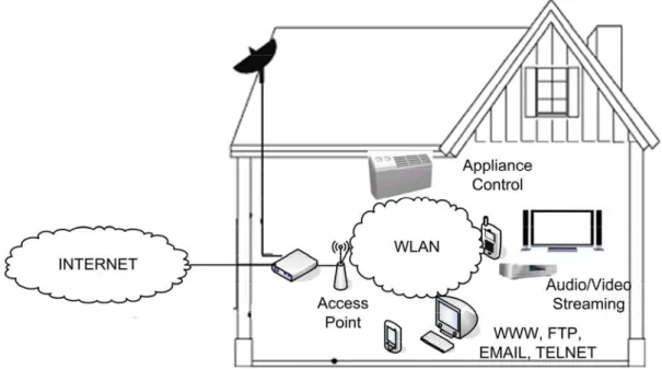
(13) Chapter 1 Introduction Home networks and their applications are now growing in popularity and are expected to provide family entertainment, security, contents, and e-commerce services. For example, consumers are getting interested in the integration of information appliances (IA) and consumer electronics (CE) that provides communication, control, security (such as monitoring or intrusion detection), and. sharing of digital contents. in home domain. There are several network options for digital home, such as the wireless local area network (WLAN), HomePlug [33], and HomePNA [34]. Among them, the WLAN is advantageous for easy installation, diminishing cost, and technical improvements, especially enhanced data rates [2][30]. As shown in Fig. 1, a WLAN integrates information appliances and digital home applications, such as video streaming from DVD players and remote control of air conditioners over WLAN. It is simultaneous the bridge between these home applications and the internet in a digital home environment. According to market surveys, users are more likely to adopt WLAN than Ethernet for constructing digital home environments [31].. 1.
(14) Fig. 1: The integration of digital home appliances using WLAN.. Video, audio, voice over IP (VoIP) and other multimedia applications are possible digital home applications and how to carry them over the WLAN becomes a key issue for WLAN-based home networks. However, real-time applications requires better performance with low mean packet delay, small misses of packet deadline, and low packet collisions; therefore it is crucial for the WLAN to provide sufficient quality of service (QoS) for real-time data in digital home environments [31]. There are diverse protocols and/or mechanisms in different layers to ensure QoS. These protocols include Session Initiation Protocol (SIP) in the application layer, RTP/RTCP in the transport layer, and MPLS, InterServ, and DiffServ in the network (IP) layer [30]. However, due to the characteristics of WLANs (high bit error rate, fading, etc.), they may still be confined by the underlying WLAN (data link and physical layer) and the QoS performance may be limited. Accordingly, it is important for WLANs to be equipped with appropriate QoS mechanisms for digital home applications. In this thesis, an integrated QoS solution for preventing the starvation problem, 2.
(15) which may cause undesirable impact on digital home applications such as http, telnet, and home appliance control applications, in IEEE 802.11e WLANs is proposed.. 3.
(16) Chapter 2 Preliminary To improve the QoS capabilities for WLANs, the IEEE 802.11 committee proposed the IEEE 802.11e specification [3], which provides QoS enhancements to the MAC layer and enables 802.11 WLANs to efficiently stream audio and video data. The IEEE 802.11e provides QoS functions by the following elements: . Hybrid Coordination Function (HCF). . Transmission Opportunity (TXOP). . Traffic Specification (TSPEC). In the following, we give a brief introduction to each.. 2.1 Hybrid Coordination Function (HCF) [3] As shown in Fig. 2, 802.11e is an extension to the legacy 802.11 standards to support diverse applications, including real-time applications, by MAC enhancements for QoS [3]. IEEE 802.11e introduces Hybrid Coordination Function (HCF) as the MAC scheme. While being compatible to legacy DCF and PCF, HCF combines both contention-free and contention-based channel access mechanisms and introduce traffic differentiation to provide QoS guarantees. The contention-based channel access mechanism in HCF is called Enhanced Distributed Channel Access (EDCA) while the counterpart is HCF Controlled Channel Access (HCCA), which is contention-free. These enhancements distinguish QoS enhanced stations (QSTAs) from non-QoS STAs (STAs), and QoS enhanced access point (QAP) from non-QoS AP (AP).. 4.
(17) Fig. 2: Protocol hierarchy of 802.11e [30].. 2.2 Transmission Opportunity (TXOP) [3] The fundamental concept of 802.11e channel access function is based on transmission opportunity (TXOP). A TXOP grants a particular QSTA the access to a channel at a defined point in time, for a defined maximum duration. In IEEE 802.11e, the HCF allocates the right to transmit through TXOPs granted to QSTAs. More specifically, a TXOP is a bounded time interval in which the QSTA is allowed to transmit a series of frames and a TXOP can only be assigned by HC. The TXOP value of a QSTA can be obtained in two ways. The first way is from a QoS+CF-Poll QoS frame during the CP or CFP (a “polled” TXOP); the other way is by a QSTA winning an instance of EDCA contention during the CP. In the first way, the entire TXOP is protected by the NAV set by the duration of the frame that contained the QoS+CF-Poll function. Meanwhile, TXOP is confined within TXOPLimit to prevent channel from being monopolized. Generally speaking, TXOP maximum shall not extend across TBTT (target beacon transmission time), dot11CFPMaxDuration (if in CFP), dot11MaxDwellTime (if using an FH PHY), dot11CAPLimit, or any other restrictions [30]. Any QoS data type frame of a subclass that includes CF-Poll contains a TXOP limit in its QoS control field. For the TXOP that comes from EDCA contention, the TXOP limit value shall be from the QoS parameter set in the most 5.
(18) recent Beacon frame. On the other hand, in the case of a polled TXOP a QSTA may initiate the transmission of one or more frame exchange sequences, with all such sequences nominally separated by a SIFS interval. The QSTA shall not initiate transmission of a frame unless the transmission, and any acknowledgement, or other immediate response expected from the peer MAC entity, are able to complete prior to the end of the remaining TXOP duration. As shown in Fig. 3, an 802.11e superframe is composed of CFP and CP, separated by a CF-End frame. It is initialized with a Beacon frame and CFP begins afterward. During CFP, a polled QSTA or STA may transmit frames within TXOP or any other constraints, such as CFPMaxDuration, as in the legacy 802.11. HC then terminates CFP by issuing CF-End and then a CP begins. During CP, a QSTA or STA may transmit frames by contenting for channel access after waiting for a backoff interval. Unlike the legacy 802.11, HC may also take over the channel in the control access phase (CAP), which is a temporary contention-free period during CP.. Fig. 3: A 802.11e superframe [3][30].. The enhanced mechanism in 802.11e relies on a set of new QoS frame types that allow the HC to send any combination of data, poll, and acknowledgement to a station 6.
(19) in a single frame. When the HC sends a poll to a QSTA, the QoS control field contains a TXOP limit value that specifies the duration of the granted TXOP [25][30].. 2.3 Traffic Specification (TSPEC) [3][30] To provide QAP the information of service requirements, QSTAs quantify their QoS requirements in the form of TSPEC (Traffic Specification) parameters. However, parameter values in TSPEC are objectives, not guarantees, and it may be unachievable for the MAC layer to provide the request bandwidth and/or service quality. A traffic specification always includes a user priority value, and optionally include quantitative objectives for, or limits on, traffic attributes such as MSDU (MAC service data unit) sizes and arrival rates, traffic characteristics such as constant vs. variable data rate, maximum delivery delay, and/or other MAC link options like acknowledgement policy. For the relationship between applications and these parameters, for a realistic instance, an AV service in SDTV (standard definition television) quality, the mean data rate is approximately 6 Mbps; while in HDTV (high definition television) quality, 24 Mbps is required [35].. 2.3.1 TSPEC frame format [3] Same as IEEE 802.11, there are three frame types in IEEE 802.11e: control, management, and data. In 802.11e, the format of a management frame is completely redefined to provide QoS functionalities. It contains fixed fields and extendable information fields. Information fields carry QoS parameters of different categories and are distinguished by Element ID, as shown in Fig. 4 For example, the information element with Element ID 12 is QoS parameter set element, containing EDCA TXOPLimit, CWmin[UP], and CWmax[UP] values; the information element with 7.
(20) Element ID 13 is TSPEC element specifying all TSPEC QoS parameters, as shown in Fig. 5.. Fig. 4: Information element format in management frame body in IEEE 802.11e [3].. Fig. 5: TSPEC element format in IEEE 802.11e [3].. As shown in Fig. 5, TSPEC element includes the following fields [3][25]: . The Inter-Arrival Interval field specifies the nominal inter-arrival interval, in units of TU (time unit), of MSDUs belonging to this traffic steam at the MAC SAP. Actual inter-arrival interval may differ from the value of this field and may not be a constant. This field provides a reference traffic specification.. . The Nominal MSDU size field specifies the nominal size, in octets, of MSDUs belonging to the TS (traffic stream) under this traffic specification.. . The Minimum Data Rate field specifies the lowest data rate, in units of 1 Kb/s, that is acceptable for transport of MSDUs belonging to this TS within the delay and jitter bounds under this traffic specification.. . The Mean Data Rate field specifies the nominal sustained data rate, in units of 1 Kb/s, for transport of MSDUs belonging to the TS within the delay and jitter bounds under this traffic specification.. 8.
(21) . The Maximum Burst Size field specifies the maximum data burst that may occur, in units of eight octets, for transport of MSDUs belonging to this TS within the delay and jitter bounds under this traffic specification.. . The Minimum TX Rate field specifies the minimum PHY rate, in units of 0.5 Mbit/s that is necessary for successful transport of this TS. A value of 0 indicates that any support rate is acceptable. This rate information is intended to ensure that TSPEC parameter values resulting from an admission control negotiation are sufficient to provide the required throughput for the traffic stream. In a typical implementation, an RS is admitted only if the defined traffic volumn can be accommodated at the specificaed rate within an amount of WM (wireless medium) occupancy time that the admissions control entity is willing to allocate to this TS.. . The Delay Bound field specifies the maximum amount of time in units of eight ms allowed to transport an MSDU belonging to this TS, measured between the time marking the arrival of the MSDU at the local MAC sublayer from the local MAC SAP and the time starting the successful transmission or transmission of the MSDU to the destination. A value of 0 indicates the maximum amount of time. allowed. to. transport. MSDUs. belonging. to. this. TS. is. dot11MaxTransmissionMSDULifetime, measured from the attempt to transmit the first fragment of the MSDU. . The Jitter Bound field specifies the acceptable maximum delay difference in units of TU in the transport of MSDUs belonging to this TS, with the delay in the transport of an MSDU measured between the time marking the arrival of the MSDU at the local MAC sublayer from the local MAC SAP and the time starting the successful transmission or retransmission of the MSDU to the destincation. A value of 0 indicates unspecified jitter bound. 9.
(22) As mentioned previously, in 802.11e, the HC is responsible for controlling the allocation of time on the medium through the use of polled TXOPs. The HC makes its decisions on TXOP allocation from TSPECs. TSPECs are sent by the QSTA, and the QAP may grant or deny a TSPEC request according to its algorithm.. 2.3.2 TSPEC mechanism [3][30] The TSPEC is the primary mechanism for communication of QoS parameters. QSTAs send TSPEC requests to the QAP in the form of an ADDTS QoS action frames. The QSTA requests TSPEC for both upstream (from QSTA to QAP) and downstream (QAP to QSTA) flows. The QAP then evaluates if there are available resources to meet the requested TSPEC. The QAP can respond by offering the QSTA an alternate TSPEC (probably with lower performance QoS parameters), or it may deny the TSPEC request completely. Even a TSPEC is established, it may still be deleted by the QSTA itself when its requirements have been changed or deleted by the QAP. Also, the QAP may unilaterally delete a QSTA's TSPEC if there are changes in the channel resources. Eventually, a TSPEC will time out if corresponding traffic does not take place within the timeout defined during the setup.. 10.
(23) Chapter 3 Existing Approaches In this chapter, we review several classical 802.11-based MAC protocols that provide QoS mechanisms. Issues, including their basic access methods, QoS capabilities, advantages, and drawbacks, are presented.. 3.1 EDCA [3] The Enhanced Distributed Channel Access (EDCA) of the IEEE 802.11e is a component of HCF in IEEE 802.11e. It is a contention-based channel access scheme and provides soft QoS guarantee, which means it may still fail, by categorizing traffic into access categories (ACs), as shown in Table 1, and each AC has its corresponding MAC parameters, which prioritize the channel accessing opportunity statistically.. 11.
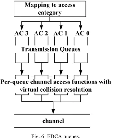
(24) Table 1: Mappings between priority and IEEE 802.11e AC [4]. Priority. Access Designation Category (AC) (informative). 1. 0. Background. 2. 0. Background. 0. 0. Best Effort. 3. 1. Video. 4. 2. Video. 5. 2. Video. 6. 3. Voice. 7. 3. Voice. EDCA enhances the original DCF by providing prioritized QoS, which supports priority based best-effort services, such as DiffServ. EDCA has been designed for support of prioritized traffic similar to DiffServ, whereas HCCA supports parameterized traffic similar to IntServ [30]. Multicast and broadcast frames are delivered by the QAP during either CP or CFP under EDCA or PCF, respectively. To provide traffic differentiation, 802.11e EDCA introduces the concept of traffic categories and is designed to provide traffic differentiation with 8 (from 0 to 7) different traffic categories (TCs), in distributed and contention-based mode. This mapping is rooted from IEEE 802.1d bridge specification. Compared to the 8 TCs, however, an 802.11e STA shall implement four access categories (ACs), from 0 to 3. Each queue of the AC corresponds to an individual prioritized transmission queue. In addition, there are contentions and virtual collision among ACs in 802.11e while contention always occur among STAs in the legacy 802.11, as illustrated in Fig. 6. Each AC queue has its own priority by different AIFS length, persistence factor (PF),. 12.
(25) CWmin and CWmax. Each AC contends for channel inside the STA. When collisions occur, only one of the contending ACs is capable of obtaining the channel access opportunity. In the IEEE 802.11e, such collisions among the contending AC is called “virtual collision” since it does not happen in physical channels. Meanwhile, even an AC wins its channel access opportunity, a collision in the physical channel with other (Q)STAs may still occur.. Fig. 6: EDCA queues.. The differentiation in priority between ACs is realized by setting different values for the AC parameters. The most important of which are listed below [30]: . Arbitrary Inter-Frame Space (AIFS): The minimum time interval between the wireless medium becoming idle and the start of transmission of a frame. Each of the AC has its own AIFS[AC], CWmin[AC], and CWmax[AC] instead of a unified DIFS, CWmin, and CWmax in the legacy 802.11. Compared to DIFS, AIFSN[AC] is an integer larger than zero and differs from one AC to another. As a result, a 13.
(26) AC’s AIFS (AIFS) is determined by the following:. AIFS[ AC ] = SIFS + AIFSN [ AC ] × Slot _ Time. (3.1). For each AC, the minimum value of AIFS is DIFS. . Contention Window (CW): A random number is drawn from this interval, or. window, for the backoff mechanism. In DCF, for each STA backoff time is one slot time multiplied by a random integer, drawn between CWmin and CWmax. By contrast, in EDCA for each AC of one QSTA, the random integer is drawn in [0, CWi] while CWi is in the range from CWmin [i] and CWmax[i]. Once a collision is detected, CW is increased in the following pattern: CWnew [ AC ] = (CWold [ AC ] + 1) × PF [ AC ] − 1. (3.2). , where PF is a traffic category dependent parameter, determining the “degree of increase” of the CW when a collision occurs. Binary backoff is one of the cases where PF equals 2. . TXOP Limit: It is the maximum duration for which a QSTA can transmit after. obtaining a TXOP. In 802.11e, it is an 8-bit field that is present in QoS data type frames with subtypes that include CF-Poll and specifies the time limit on a TXOP granted by a QoS(+)CF-Poll from an HC within a QBSS. In QoS data type frames with subtypes that include CF-Poll, the addressed QSTA is granted a TXOP that begins a SIFS period after this frame and lasts no longer than the number of 32-microsecond periods specified by the TXOP limit value.. When data arrives at the service access point (SAP), the 802.11e MAC first classifies the data with the appropriate AC, and then pushes the newly arrived MSDU into the appropriate AC transmit queue. MSDUs from different ACs contend for EDCA-TXOP internally within the QSTA. The internal contention algorithm calculates the backoff, independently for each 14.
(27) AC, based on AIFS, contention window, and a random number. The backoff procedure is similar to that in DCF, and the AC with the smallest backoff wins the internal contention. As illustrated in Fig. 7, the winning AC would then contend externally for the wireless medium. The external contention algorithm has not changed significantly compared to DCF, except that in DCF the deferral and backoff are constant for a particular PHY. 802.11e has changed the deferral and backoff to be variable, and the values are set according to the appropriate AC.. Fig. 7: External contention and backoff in EDCA [3].. However, according to [8][14], even EDCA provides significant traffic differentiation for QoS, a problem called “low priority traffic starvation” accompanies with traffic differentiation. This problem occurs when the number of high priority traffic increases, traffic in low priority AC is starved, meaning unable to access channels and throughput drops to zero, rather fast.. 15.
(28) 3.2 HCCA [3] HCF Controlled Channel Access (HCCA) is another component of HCF in IEEE 802.11e and intends to increase efficiency by reducing the contention on the medium. HCCA inherits some of the rules of legacy PCF and provides support for parameterized QoS. Similar to PCF, HCCA provides QoS polled access to the wireless medium and a hybrid coordinator (HC), which locates within a QAP and is responsible for traffic scheduling based on admitted TSPECs. Same as PCF, HCCA controls the iteration of CFP and CP by using Beacon and CF-End frames. The HC is responsible for controlling the allocation of time on the medium through the use of polled TXOPs. However, while PCF can only take effect in the contention-free period (CFP) between Beacon and CF-End frames, HCCA QoS polling, issued by an HC, can take place during both CFP and contention period (CP). Another difference is while TXOP does not exist in the legacy 802.11, HCCA TXOP is assigned to a QSTA by polling a QoS+CF-Poll frame. Accordingly, IEEE 802.11e defines new QoS frame types that allow the HC to send any combination of data, poll, and acknowledgement to a station in a single frame. When the HC sends a poll to a QSTA, the QoS control field contains a TXOP limit value that specifies the duration of the granted TXOP. In the HCCA mechanism, all QSTAs shall be able to respond to QoS+CF-Polls received from an HC.. All STAs and QSTAs inherently obey the medium access. rules of the HCF because these rules are based on the DCF. The central concept of HCCA is the controlled access phase (CAP), which is a bounded time interval and formed by concatenating a series of HCCA (polled) TXOPs. Scheduling of HCCA (polled) TXOP and formation of CAP are performed by the HC. As mentioned previously, by contrast with PCF, HCCA can theoretically operate during both CFP 16.
(29) and CP. However the 802.11e standard recommends using HCCA during CP only, and discourages its use during CFP. This is mainly due to the complexity in implementing polling used CF-Poll and QoS CF-Poll at the same time.. Fig. 8: An example CAP activity [3][30].. An example CAP activity is shown in Fig. 8. A QoS-Data frame is transferred between QAP and QSTA in both EDCA and HCCA. An HCCA-TXOP of a QSTA is granted by QoS CF-Poll or QoS Data+QoS-Poll frame. When a QSTA has nothing to transmit or in the last frame of its TXOP, QSTA issues a QoS-Null, indicating no more data to send. Meanwhile, a QSTA may request a TXOP, QAP responses with QoS CF-Ack or QoS-Data+CF-ACK. For scheduling in HCCA, HC has to decide which QSTA to allocate polled TXOPs. This involves the following considerations: [30] . Priority of the TS. . Required QoS for the TS. . Queue length for each AC. . Queue length per station. . Duration of TXOP available to be allocated. . Past QoS seen by the TS In addition, when a wireless station gets a TXOP by polling from the HC, the HC. does not specify a particular AC for the TXOP. Each QSTA makes its own decision to 17.
(30) allocate the polled TXOP to an AC.. 3.3 Distributed Deficit Round Robin (DDRR) [12] DDRR [12][24] is an MAC protocol that addressed starvation prevention for low priority traffic. It attempts to resolve unfair allocation of bandwidth between high and low priority traffic, as well as variance of throughput and delay, that are resulted from the unfairness of transmission opportunities and bandwidth allocations. The DDRR is based on Deficit Round Robin scheduling [13], which is a fair bandwidth allocation mechanism. In DDRR, traffic at each MS is categorized into classes with different QoS requirements. A traffic class i is allotted a service quantum Q bits every Ti seconds, depending on the throughput requirement. Thereof traffic classes requiring a higher throughput receive the service quantum at a faster rate. DDRR determines an appropriate IFS in order to balance both traffic differentiation and potential starvation. In short, DDRR employs a deficit counter and service quantum to determine IFS: IFS i j (t) = DIFS − α ×. DC i j (t) × Random( 1,β ) Q. (3.4). DCi j(t) = DCi j(t ′) +. Q × (t − t ′) Ti. (3.5). DCi j(t) = DCi j(t) − Frame_Size(t). (3.6). , and the deficit counter of traffic class i at station j at any given time is donated by. DCi j , and it is proportional to the bandwidth available to this traffic class at that time. The value of DCi j is increased continuously with time at a rate of Q bits every Ti seconds and is decreased by the size of the frame whenever a frame is transmitted. The value of DCi j is bounded between zero and. 18. DIFS − PIFS. α. × Q such that the.
(31) value of IFS i j is bounded between PIFS and DIFS. Accordingly, the largest value of IFS in DDRR is equal to DIFS, which makes DDRR backward compatible to the legacy IEEE 802.11. If DCi j of traffic class i falls below a minimum requirement, this traffic class have to wait until its DCi j becomes higher than the minimum requirement before the next transmission. In addition, as shown in (3.4), the backoff process is eliminated and replaced by random(1.0, β), where β > 1.. 3.4 Comparison To sum up, the legacy IEEE 802.11 contention-based DCF provides inadequate QoS functions for supports of real time traffic and traffic differentiation. The contention-free PCF is anticipated providing MAC service for real time applications by offering reduced collision rate and a central traffic scheduler that is responsible for traffic coordination within a BSS. However, according to the evaluations in [14][15][16], it still has relatively poor throughput, channel capacity, and high traffic overhead with the increasing number of high priority nodes. In addition, PCF has neither a specification for transforming an application’s QoS requirements into MAC parameters, nor how to carry and exchange these QoS requirements among stations. As a result, any solutions based on PCF have to provide scheduling functions or traffic differentiation algorithms for real time applications; therefore it lacks of compatibility. In contrast, the IEEE 802.11e EDCA provides traffic differentiation, traffic specification, and mechanisms to carry TSPEC. However, as described in section 3.1, EDCA suffers from the starvation problem of low-priority traffic while the channel is occupied by a large mount of high-priority traffic. Due to the characteristics of digital 19.
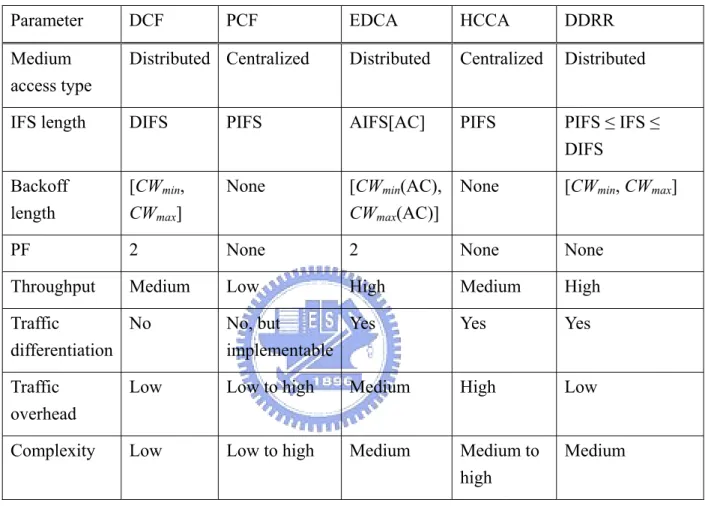
(32) home applications, such as carrying mixed traffic, this starvation prevention is critical when deploying WLAN as a home networking infrastructure.. Table 2: Comparison of various WLAN MAC mechanisms. Parameter. DCF. Medium access type. PCF. EDCA. HCCA. DDRR. Distributed Centralized. Distributed. Centralized. Distributed. IFS length. DIFS. PIFS. AIFS[AC]. PIFS. PIFS ≤ IFS ≤ DIFS. Backoff length. [CWmin, CWmax]. None. [CWmin(AC), CWmax(AC)]. None. [CWmin, CWmax]. PF. 2. None. 2. None. None. Throughput. Medium. Low. High. Medium. High. Traffic No differentiation. No, but Yes implementable. Yes. Yes. Traffic overhead. Low. Low to high. Medium. High. Low. Complexity. Low. Low to high. Medium. Medium to high. Medium. Table 2 compares various MAC mechanisms [1][3][12][15][24][25][30]. For the IFS length, DDRR provides a variable IFS to achieve channel access prioritization. For the same reason, EDCA provides different (CWmin(AC), CWmax(AC)) value for each AC while the other MAC mechanisms offer a constant (CWmin, CWmax). In addition, both EDCA and HCCA provide by-traffic traffic differentiation while DDRR can only offer by-station traffic differentiation. PCF, however, does not provide any traffic differentiation in its specification; it can be achieved by external scheduling mechanisms. 20.
(33) Also as shown in Table 2, the traffic can be coordinated by a centralized coordinator, such as PCF and HCCA; or a distributed approach, like DCF, EDCA, and DDRR. The centralized approach is more effective but suffers higher algorithm complexity and traffic overhead. By contrast, the distributed approaches provide traffic coordination using adjustment for IFS or CW. However, they are usually static approaches, or have difficulty making optimization dynamically.. 21.
(34) Chapter 4 Proposed Starvation Prevention for Low Priority Traffic Scheme 4.1 SPLPT Overview To improve the starvation problem of low priority traffic and to provide a QoS mechanism for digital home applications in WLANs, we propose an integrated 802.11e-based QoS scheme, namely Starvation Prevention for Low-Priority Traffic (SPLPT), which is an integration of EDCA and HCCA. SPLPT adopts the contention-based EDCA in normal cases; but it can also provide a compensation procedure for traffic that is about to starve by using a contention-free MAC mechanism, HCCA. SPLPT includes two parts: a QoS request procedure, which is identical to that in IEEE 802.11e, and a compensation procedure for starving traffic (CPST). Once EDCA allocates most of the channel resources for high priority traffic when the load is high, the CPST will be activated to avoid sacrificing the performance of low priority traffic when starvation is about to occur. Compared to the legacy IEEE 802.11 PCF, which was anticipated to provide contention-free MAC access for high priority (real time) traffic, SPLPT takes a different way to adopt contention-free MAC access for starving low priority traffic. The compensation procedure becomes particularly important when applications like. telnet, ftp, and http come under low priority (AC 0) in EDCA; and starvation may result in these applications in failure due to timeout when the WLAN is heavily. 22.
(35) loaded by high priority streaming applications. In this situation, SPLPT offers contention-free channel access opportunity for low priority traffic and prevents these applications from failure while minimizing the impact on high priority traffic. Note that the compensation procedure in SPLPT will not be activated if EDCA provides sufficient access opportunities for all traffic.. Fig. 9: Traffic stream life cycle in SPLPT [3]. 23.
(36) Fig. 10: SPLPT operation flow.. 4.2 QoS Request Procedure of SPLPT We adopted IEEE 802.11e HCCA as the contention-free MAC protocol for compensating low priority traffic in SPLPT. It is because SPLPT can be benefited from the IEEE 802.11e HCCA mechanism by its QoS information exchange specification based on TSPEC parameters. Another reason for adopting HCCA rather than 802.11 PCF is that HCCA can also operate during CP, which reduces complexity from implementing CF-Poll and QoS CF-Poll at the same time. Finally, HCCA is a must in 802.11e while PCF is only optional in the legacy 802.11. By using HCCA ensures that SPLPT is compatible to the IEEE 802.11e specifications. As shown in Fig. 9, low priority traffic nodes submit their QoS requirements in TSPEC format using ADDTS QoS action request [4] to the HC. According to [3], it is always the responsibility of the QSTA to initiate the creation of a TS, regardless of the direction 24.
(37) of each traffic. Initially a TS is inactive and a QSTA cannot transmit any QoS Data MPDUs using an inactive TS. While a successful TS setup is initiated, the TS becomes active, the parameters of the TSPEC characterizing the TS can be re-negotiated, initiated by the QSTA; and the result can be successful or failed. Also, when an active TS becomes inactive, a TS deletion is then initiated at the HC. It also becomes inactive following a TS timeout deleted at the HC [3]. While Fig. 9 is the traffic stream (TS) life cycle for a QSTA in SPLPT [3], Fig. 10 is the flowchart of a HC that implements SPLPT. When the HC receives the QoS request, it verifies the contents according to the status at that time. In our SPLPT implementation, HC takes the following considerations into the decision whether accepts the request or not: . Number of about to starve low priority traffic it is serving.. . The inter-arrival interval specified in the TSPEC format.. If there has been too much starving traffic such that the HC cannot handle anymore or the contents in traffic specification (TS) is a “greedy request,” for instance, a very short inter-arrival time, the HC will responsed with status code 4, as shown in Table 3 [3], indicating the TS has been rejected. Otherwise, a status code 0 is returned and the TS has been created. The starving traffic is modeled into TSPEC QoS parameters and feed them back to the HC through 802.11e MAC specifications. The HC is therefore capable of performing the compensation mechanism with reference to these QoS parameters. However, same as 802.11e specifications, the TSPEC parameters are objectives, not guarantees, and the HC may only give a permit of a minimum QoS for the low priority traffic in order not to cause obvious side-effects on the overall throughput or high priority traffic.. 25.
(38) Table 3: The TS action-specific status codes defined in [3]. Status Code. Result Code. Definition. 0. Action completed successfully. The TS has been created with the parameters contained in the action request frame.. 1. Unrecognized action. This should not occur.. 2. INVALID_PARAMTERS. No TS has been created because one or more parameters have invalid values.. 3. ALTERNATIVE. The TS has been created with the parameters contained in the response frame. These are not the same as the parameters in the request frame.. 4. REFUSED. The TS has not been created because the request cannot be honored at this time due to other QoS commitments.. As mentioned previously, the QSTA, which is collocated with an HC, may unilaterally delete a QSTA's TS if there are changes in the channel condition that reduces available bandwidth. Also, a TS will time out if corresponding traffic does not take place within the timeout defined during the setup.. 26.
(39) 4.3 Compensation Procedure for Starving Traffic (CPST) As shown in Fig. 10, when the inter-arrival time exceeds the threshold specified, indicating low priority traffic is about to starve, the low priority traffic is introduced into the HCCA compensation procedure for starving traffic (CPST) by the HC. Then, the HC calculates an appropriate TXOP for the traffic according to the specified TS and the HC’s current status. However, if the load of CPST exceeds a predefined threshold, the HC may still delete the TS previously granted in order to serve the starving traffic which has been granted. In our SPLPT implementation, the length of a HCCA queue is a constant. When the queue is full, meaning that HC is serving too many starving nodes, all of TS requests will be suspended until the compensation queue is available again. In this case, these nodes may still fall into starvation. The determination of a TXOP depends on both TS and the current traffic status. Due to the traffic status may subject to change, the HC may still fail to allocate a TXOP for a starving traffic even when its QoS requirement has just been accepted but the calculated TXOP is less than 0. In this case, the HC will not assign a TXOP in this iteration but adds a proper weight for this traffic and allocate another TXOP in the next iteration with higher priority. As shown in Fig. 10, this is a weighted queue procedure. Once the TXOP is decided, it should be passed to the corresponding QSTA by QoS+CF-Poll frames in the beginning of a CAP. When receiving the polled TXOP, a starving station begins to run CPST. The compensation procedure stays active until the TXOP reaches or be reset to zero. The HC may reset all low priority nodes’ TXOPs to zero when the load of high priority traffic is reduced; or the termination of the low priority traffic. As a result, these stations are forbidden to access channels and 27.
(40) can only transmit MAC frames by contenting for channels in EDCA.. 28.
(41) Chapter 5 Evaluation and Discussion In this chapter, the simulation environment is first described. Then, simulation results are evaluated and discussed. We compare SPLPT with the IEEE 802.11e EDCA and DDRR for the evaluation of starvation prevention.. 5.1 Simulation Environment In the simulation, we used Network Simulator 2 (ns-2) [20] with 802.11e extension developed by [21] as the simulation tool. In addition, to analyze ns-2 trace files, we used the tool developed by Jaroslaw Malek [22]. In order to simplify the analysis, we had only one high and one low ACs, as in [14], and the numbers of high and/or low priority nodes were based on the analysis for wireless home network applications in [27] . Parameters used in our simulation are referred from [5], and are shown in Table 4.. 29.
(42) Table 4: Simulation parameters [5] IEEE 802.11 Configuration. DIFS. 50 µs. PIFS. 30 µs. SIFS. 10 µs. aSlotTime. 20 µs. PF. 2. PSDU bit rate. 11 Mbps. PLCP preamble and header bit rate. 1 Mbps. AIFSN. 2 (High) / 7 (Low). CWmin. 15 (High) / 31 (Low). CWmax. 31 (High) /1023 (Low). TXOP Limit. 5 msec (High) / 0 msec (Low). CAP timer update time. 5120 µs. dot11CAPRate. 21 µs. dot11CAPMax. 5040 µs. Medium Configuration. BER. 1.3 E-5. Traffic Configuration. Average inter-arrival time. 0.001 (High) / 0.012 (Low). Average frame size. 1464 (High) / 1500 (Low). EDCA Configuration. HCCA Configuration. 5.2 Simulation Results and Discussion SPLPT starts its compensation procedure when the inter-arrival time falls behind the requirement specified in TSPEC and the compensation procedure is expected to allocate 5% of the maximum throughput for all low priority traffic.. 5.2.1 Case 1: Six low priority nodes In the case of six low priority nodes, the SPLPT compensation procedure activates when there are more than 8 high priority nodes, as shown in Fig. 11 and Fig. 12,. Before the compensation procedure takes action, SPLPT has the same behavior as 30.
(43) EDCA. During the activation of the compensation procedure, the throughput of SPLPT then drops from 3% to 7%, compared to that of EDCA. In comparison with DDRR, the throughput of SPLPT drops from 6% to 12%. Meanwhile we can observe that DDRR has better throughput than EDCA (3% ~ 5% improvement) but with higher variation. Though SPLPT reduces the throughput of high priority traffic, it has significant performance in starvation prevention. As shown in Fig. 12, compared to EDCA, the normailized throughput of low priority traffic has been enhanced from 0 % to 5 %. This is significant because digital home applications of low priority which can hereby escape from starvation and service failure.. Normailized throughput. 1 0.8 0.6 0.4 EDCA (H) SPLPT (H) DDRR (H). 0.2 0 1. 2. 3. 4. 5. 6. 7. 8. 9. 10. 11. 12. 13. 14. 15. Number of high priority nodes. Fig. 11: Normalized throughout of high priority traffic for the case of 6 low priority nodes.. 31.
(44) Normailized throughput. 1 0.8 0.6 0.4 EDCA (L) SPLPT (L) DDRR (L). 0.2 0 1. 2. 3. 4. 5. 6. 7. 8. 9. 10. 11. 12. 13. 14. 15. Number of high priority nodes. Fig. 12: Normalized throughput of low priority traffic for the case of 6 low priority nodes.. 5.2.2 Case 2: Twelve low priority nodes In the twelve low priority nodes case, the SPLPT compensation procedure is activated when there are 7 high priority nodes, as shown in Fig. 13 and Fig. 14. Fig. 13 is the throughput variation for high priority nodes. During the compensation procedure, the throughput of SPLPT drops from 4% to 12%, compared to that of EDCA. Compared to DDRR, the throughput of SPLPT drops from 6% to 14%. Likewise, we can observe that DDRR has better throughput than EDCA but with higher throughput variation than the case 1. SPLPT has indeed prevented starvation in this case as well. As shown in Fig. 14, compared to EDCA, the normalized throughput of low priority traffic has been enhanced from 0 % to 5 %. Again, low priority traffic can hereby escape from. 32.
(45) starvation and service failure.. 1. Normalized throughput. 0.8. 0.6. 0.4 EDCA (H) SPLPT (H) DDRR (H) 0.2. 0 1. 2. 3. 4. 5. 6. 7. 8. 9. 10. 11. 12. 13. 14. 15. Number of high priority nodes. Fig. 13: Normalized throughput of high priority traffic for the case of 12 low priority nodes.. 33.
(46) 1. Normalized throughput. 0.8. 0.6. 0.4 EDCA (L) SPLPT (L) DDRR (L) 0.2. 0 1. 2. 3. 4. 5. 6. 7. 8. 9. 10. 11. 12. 13. 14. 15. Number of high priority nodes. Fig. 14: Normalized throughput of low priority traffic for the case of 12 low priority nodes. As demonstrated in the simulation for throughput, EDCA provides efficient MAC service and traffic differentiation with significantly distinct throughput between high and low priority traffic. With a small number of high priority nodes, low priority traffic holds sufficient throughput. However, with the increasing number of high priority traffic nodes, we observed that the low priority traffic of EDCA began to starve rather fast and eventually all low priority traffic nodes were starved with almost zero throughput. In the simulation, low priority traffic was starved when there were more than 7 high priority nodes. This simulation result agrees with that in [14]. In the simulation we found DDRR provided better throughput and lower average MAC delay for high priority traffic than 802.11e and SPLPT. However, it had comparatively lower throughput and higher MAC delay than 802.11e and SPLPT. It is also noticeable that DDRR had significant variation in throughput and MAC access. 34.
(47) delay. In addition DDRR could not achieve “starvation prevention” in our simulation. To sum up, according to Fig. 12 and Fig. 14, SPLPT is capable of providing a static throughput for low priority when it is about to starve. In both simulated cases, compared to EDCA, the normalized throughput of low priority traffic was enhanced from 0 % to 5 %. This is important because applications of low priority can hereby escape from starvation and service failure.. 5.2.3 MAC delay at the starving point Fig. 15 and Fig. 16 illustrate the MAC delay among SPLPT, EDCA, and DDRR while they reach the starving point. The starving point is the numbers of high and low priority nodes when the traffic is about to be starve. Before reaching the starving point, SPLPT has the same performance as EDCA. In contrast, EDCA and DDRR may have a very high MAC delay due to starvation when exceeding the starving point. As shown in Table 5 and 6, SPLPT(H) (high priority traffic in SPLPT) has slightly longer MAC delay due to the delay resulted from the compensation procedure which serves the starving low priority traffic. However, SPLPT significantly reduces the MAC delay of low priority traffic. SPLPT(L) (low priority traffic in SPLPT) has the shortest average MAC access delay among three low priority traffic MACs because it guarantees HCCA contention-free access for low priority traffic when it is about to starve. However, with the increasing number of starving low priority traffic nodes, MAC delay rises significantly because SPLPT needs to allocate limited controlled access phases (CAPs). The length of CPST is limited in order to reduce the side-effects in high priority traffic performance. For high priority nodes, SPLPT(H) has higher MAC delay than DDRR(H) and EDCA(H) due to CAPs, while DDRR(H) has shorter average MAC delay than EDCA(H), but the difference between DDRR. 35.
(48) and EDCA is not much.. EDCA (H). 16. EDCA (L) SPLPT (H) SPLPT (L). 14. DDRR (H) DDRR (L). MAC delay (msec). 12 10 8 6 4 2 0 0. 1. 2. 3. 4 5 6 Simulation time (sec)). 7. 8. Fig. 15: MAC delay for the case of H = 8 and L = 6.. Table 5: Average MAC delay statistics of H = 8 and L = 6 MAC Mechanism. Average MAC Delay (ms). EDCA(H). 0.67. EDCA(L). 8.54. SPLPT(H). 0.93. SPLPT(L). 2.19. DDRR(H). 0.63. DDRR(L). 11.17. 36. 9. 10.
(49) EDCA (H) EDCA (L) SPLPT (H) SPLPT (L) DDRR (H) DDRR (L). 26. 24. 22. 20. 18. MAC dealy (msec). 16. 14. 12. 10. 8. 6. 4. 2. 0 0. 1. 2. 3. 4. 5. 6. 7. Simulation time (sec). 8. 9. 10. Fig. 16: MAC delay for the case of H = 8 and L = 12.. Table 6: Average MAC delay statistics of H = 8 and L = 12 MAC Mechanism. Average MAC Delay (ms). EDCA(H). 1.53. EDCA(L). 16.88. SPLPT(H). 2.07. SPLPT(L). 7.25. DDRR(H). 1.21. DDRR(L). 18.52. To sum up, as shown in Table 7, SPLPT provides an efficient starvation prevention mechanism than DDRR. In addition, it preserves both of the advantages of EDCA and 37.
(50) HCCA, including support for real time traffic and design flexibility.. Table 7: Comparison of SPLPT with classical WLAN MAC mechanisms. Parameter. EDCA. HCCA. DDRR. SPLPT (proposed). Throughput. High. Medium. High. Medium to high. Traffic Yes, by differentiation traffic. Yes, by traffic. Yes, by traffic. Yes, by traffic. Traffic overhead. Medium. High. Low. High. QoS support for real-time traffic. High. High. Medium. High. QoS specifications. None. All parameters Throughput only specified in TSPEC. All parameters specified in TSPEC. Starvation prevention. No. No, but Yes implementable. Yes and efficient. Complexity. Medium. Medium to high. Medium to high. 38. Medium. more.
(51) Chapter 6 Conclusions and Future Work 6.1 Concluding Remarks QoS management is one of the most important issues for WLAN digital home applications. The simulation has shown that SPLPT efficiently resolves the starvation problem of low priority traffic by slightly reducing the throughput of high priority traffic. Since digital home applications consist of a variety of traffic, starvation of low priority traffic may result in some applications in failure, which is unacceptable. Simulation results have also shown SPLPT shortens the MAC delay of low priority traffic by 3.9 and 5.1 times, respectively, compared to EDCA and DDRR. In addition, the throughput of low priority traffic is raised up from 0 % to 5 % of the maximum throughput to avoid starvation. Therefore, SPLPT can be effectively incorporated to an IEEE 802.11e-based MAC protocol for starvation prevention in digital home applications.. 6.2 Future Work In the SPLPT implementation, we assumed TSPEC was static and would not change after the ADDTS QoS Action frame was sent in order to simplify the simulation. Although such simplification did not affect the correctness of the performance evaluation, we will implement a complete traffic stream operation specified in [3] in order to further study a cross-layer QoS request solution that is an important issue worth studying. 39.
(52) Bibliography [1] IEEE Std 802.11b, IEEE Standard for Wireless LAN Medium Access Control (MAC) and Physical Layer Specifications: Higher-Speed Physical Extension in the 5GHz Band, 1999. [2] IEEE Std 802.11a, IEEE Standard for Wireless LAN Medium Access Control (MAC) and Physical Layer Specifications: Higher-Speed Physical Extension in the 2.4 GHz Band, 1999. [3] IEEE Draft Std 802.11e, Medium Access Control (MAC) Enhancements for Quality of Services (QoS), D4.4, Jun. 2003. [4] IEEE 802.11 WG, IEEE 802.11e/D5.0, “Draft Supplement to Standard for Telecommunications and Information Exchange Between Systems – LAN / MAN Specific Requirements – Part 11: Wireless Medium Access Control (MAC) and Physical Layer (PHY) Specifications: Medium Access Control (MAC) Enhancements for Quality of Service (QoS),” Aug. 2003. [5] C. Ottoamakorn and D. Bushmitch, “Resource Management and Scheduling for the QoS-Capable Home Network Wireless Access Point,” in Proc. of IEEE CCNC, Jan. 2004, pp. 7-12. [6] Sunghyun Choi, et al., “IEEE 802.11e Contention-Based Channel Access (EDCA) Performance Evaluation,” in Proc. IEEE IC, Anchorage, Alaska, USA, May 2003. [7] S. Mangold, Sunghyun Choi; G.R. Hiertz; O. Klein, B. Walke, “Analysis of IEEE 802.11e for QoS Support in wireless LANs,“ IEEE Wireless Communications, Volume: 10 , Issue: 6 , Dec. 2003, pp. 40-50.. 40.
(53) [8] S. Mangold, S. Choi, P. May, O. Klein, G. Hiertz, and L. Stibor. "IEEE 802.11e. Wireless LAN for Quality of Service," in Proc. of the European Wireless, volume 1, Florence, Italy, Feb. 2002, pp. 32-39. [9] N.H. Vaidya, P. Bahl and G. Gupta, “Distributed Fair Scheduling in a Wireless LAN,” in Proc. of Sixth Annual International Conference on Mobile Computing. and Networking, Boston, 2000, pp. 167-178. [10] J. L. Sobrinho and A. S. Krishnakumar. “Real-Time Traffic over the IEEE 802.11 Medium Access Control Layer,” Bell Labs Technical Journal, pp. 172–187, Autumn 1996. [11] J. L. Sobrinho and A. S. Krishnakumar, “Quality-of-Service in Ad Hoc Carrier Sense Multiple Access Networks,” IEEE JSAC, vol. 17, no. 8, pp. 1353-68, Aug. 1999. [12] Wason. Pattara-Atikom,. Sujita. Banerjee,. and. Prashant. Krishnamurthy,. “Starvation Prevention and Quality of Service in Wireless LANs,” in Proc. IEEE. Wireless Personal Multimedia Communications (WPMC), October 2002, pp. 915-924. [13] M. Shreedhar and G. Varhese, “Efficient Fair Queuing Using Deficit Round Robin,” IEEE/ACM Transcations on Networking, vol. 4, no. 3, pp.375-85, 1996. [14] Anders Lindgren. Andreas Almquist, and Olov Schelen, “Evaluation of Quality of Services Schemes for IEEE 802.11 Wireless LANs,” in Proc. of the 26th. Annual IEEE Conference on Local Computer Networks (LCN 2001),. Nov. 2001.. [15] Anders Lindgren, Andreas Almquist and Olov Schelén, “Quality of Service Schemes for IEEE 802.11 - A Simulation Study,” in Proc. of the Ninth. International Workshop on Quality of Service (IWQoS 2001), June 6-8, 2001. [16] Andreas Köpsel, et al., “A Performance Comparison of Point and Distributed Coordination Function of an IEEE 802.11 WLAN in the Presence of Real-Time 41.
(54) Requirements,” in Proc. of 7th Intl. Workshop on Mobile Multimedia. Communications, Oct. 23-26, 2000. [17] G. Anastasi, et al., “QoS Privoided by the IEEE 802.11 Wireless LAN to Advanced. Data. Applications:. a. Simulation. Analysis,”. http://www.gta.ufrj.br/~rezende/cursos/eel879/trabalhos/80211e/qos.pdf. [18] Oran Sharon and Eitan Altman, “ An Efficient Polling MAC for Wireless LANs," IEEE Trans. on Networking, Vol. 9, No. 4, pp. 439-451, Aug 2001. [19] B. Bianchi, “Performance Analysis of the IEEE 802.11 Distributed Coordination Function,” IEEE JSAC, vol. 18, no. 3, pp. 535-547, Mar. 2000. [20] The VINT Project., Network Simulator 2 – ns-2: Documentation, Available: http://www.isi.edu/nsnam/ns/. [21] S. Wiethölter and C. Hoene. “An IEEE 802.11e EDCA and CFB Simulation Model for ns-2,” Available: http://www.tkn.tu-berlin.de/research/802.11e_ns2/. [22] J. Malek. “Trace Graph: a Network Simulator ns-2 Trace Files Analyzer,” Available: http://www.geocities.com/tracegraph/ [23] H. Fattah and C. Leung, “An Overview of Scheduling Algorithms in Wireless Multimedia Networks,” IEEE Wireless Communications, pp. 76-83, Oct. 2002. [24] Wasan Pattara-Atikom, Prashant Krishnamurthy, and Sujata Banerjee, “Distributed Mechanisms for Quality of Services in Wireless LANs,” IEEE. Wireless Communications, pp. 26-34, Jun. 2003. [25] Antonio Grilo, Mario Macedo, and Mario Nunes, “A Scheduling Algorithm for QoS Support in IEEE 802.11e Networks,” IEEE Wireless Communications, pp. 36-43, Jun. 2003. [26] Sungyun Choi and Kang G. Shin, “A Unified Wireless LAN Architecture for Real-Time and Non-Real-Time Communication Services," IEEE/ACM Trans.. On Networking (TON), vol. 8, no. 1, pp. 44-59, Feb., 2000. 42.
(55) [27] Chiu Ngo, “A Service-Oriented Wireless Home Network,” in Proc. IEEE CCNC, Jan. 2004, pp. 618-620. [28] Wasan Pattara-Atikom, et al., “Distributed Mechanisms for Quality of Service in Wireless LANs,” IEEE Wireless Communications, pp. 26-34, Vol. 10, No. 3, Jun. 2003. [29] Aura Ganz and Anan Phonphoem, “Robust SuperPoll with Chaining Protocol for IEEE 802.11 Wireless LANs in Support of Multimedia Applications,” Wireless. Networks, pp. 65-73, 2001. [30] S. Chung and K. Piechota. (2004 Jul), “Understanding the MAC impact of 802.11e.. Silicon. and. Software. Systems,”. Available:. http://www.commsdesign.com/showArticle.jhtml?articleID=16502136. [31] Frank Ohrtmann, “Voice over 802.11,” Artech House, Feb. 2004. [32] Voice. over. Wi-Fi. Capacity. Planning,. Proxim.. Available:. http://www.proxim.com/learn/library/whitepapers/voice_over_wifi_capacity_plan ning.pdf. [33] HomePlug Powerline Alliance. http://www.homeplug.org. [34] Home Phoneline Networking Alliance. http://www.homepna.org. [35] QoS Control Technology in Wireless AV Communication System. Sharp. Technology. Journal,. Issue. 87.. Dec.. Avaliable:http://www.sharp.co.jp/corporate/rd/22/pdf/87-08.pdf.. 43. 2003..
(56)
數據
![Fig. 2: Protocol hierarchy of 802.11e [30].](https://thumb-ap.123doks.com/thumbv2/9libinfo/8388078.178565/17.892.277.614.149.328/fig-protocol-hierarchy-of-e.webp)
![Fig. 3: A 802.11e superframe [3][30].](https://thumb-ap.123doks.com/thumbv2/9libinfo/8388078.178565/18.892.132.759.492.979/fig-a-e-superframe.webp)
![Fig. 5: TSPEC element format in IEEE 802.11e [3].](https://thumb-ap.123doks.com/thumbv2/9libinfo/8388078.178565/20.892.141.762.401.518/fig-tspec-element-format-ieee-e.webp)
+7
![Table 1: Mappings between priority and IEEE 802.11e AC [4]. Priority Access Category (AC) Designation (informative) 1 0 Background 2 0 Background 0 0 Best Effort 3 1 Video 4 2 Video 5 2 Video 6 3 Voice 7 3 Voice](https://thumb-ap.123doks.com/thumbv2/9libinfo/8388078.178565/24.892.248.639.151.534/mappings-priority-priority-category-designation-informative-background-background.webp)
![Fig. 7: External contention and backoff in EDCA [3].](https://thumb-ap.123doks.com/thumbv2/9libinfo/8388078.178565/27.892.149.757.481.777/fig-external-contention-backoff-edca.webp)
![Fig. 8: An example CAP activity [3][30].](https://thumb-ap.123doks.com/thumbv2/9libinfo/8388078.178565/29.892.134.758.273.433/fig-an-example-cap-activity.webp)
![Fig. 9: Traffic stream life cycle in SPLPT [3]](https://thumb-ap.123doks.com/thumbv2/9libinfo/8388078.178565/35.892.137.756.374.902/fig-traffic-stream-life-cycle-splpt.webp)
相關文件
For the primary section, the additional teaching post(s) so created is/are at the rank of Assistant Primary School Master/Mistress (APSM) and not included in calculating the
` Sustainable tourism is tourism attempting to make a low impact on the environment and local culture, while helping to generate future employment for local people.. The
prevent cruelty and alleviate suffering, and through education to cultivate a deep respect for life in the community so that all living creatures may live.. together
In this chapter, a dynamic voltage communication scheduling technique (DVC) is proposed to provide efficient schedules and better power consumption for GEN_BLOCK
In this thesis, we have proposed a new and simple feedforward sampling time offset (STO) estimation scheme for an OFDM-based IEEE 802.11a WLAN that uses an interpolator to recover
Lecture 1: Introduction and overview of supergravity Lecture 2: Conditions for unbroken supersymmetry Lecture 3: BPS black holes and branes. Lecture 4: The LLM bubbling
Lecture 1: Introduction and overview of supergravity Lecture 2: Conditions for unbroken supersymmetry Lecture 3: BPS black holes and branes.. Lecture 4: The LLM bubbling
Moreover, for the merit functions induced by them for the second- order cone complementarity problem (SOCCP), we provide a condition for each sta- tionary point to be a solution of
