Third-Person Interactive Control of Humanoid
with Real-Time Motion Planning Algorithm
Shu-Wei Hsu
Tsai-Yen Li
Computer Science Department Computer Science Department
National Chengchi University National Chengchi University
[email protected] [email protected] Abstract - Interactive avatar control means a control
mechanism using AI techniques to improve user navigation efficiency as well as visual realism in a 3D virtual environ-ment. This paper reports a novel approach to enhancing intel-ligent navigation interface with a third-person control mecha-nism. We use the concept of CT-space roadmap to design a new motion planning algorithm that can generate collision-free motions for the upper-body of an avatar walking in a clut-tered virtual environment. We have designed a mechanism to allow motion generation and execution to occur in parallel such that collision-free motions can be generated in real time. We believe that this type of intelligent interface can enhance the efficiency of avatar navigation as well as improve the real-ism of the generated avatar motions. The same techniques can also be applied to the motion control of humanoid robots to avoid obstacles in real time.
Index Terms – Motion planning, avatar control, real-time planning, intelligent user interface, CT-space roadmap
I. INTRODUCTION
Due to the recent advances in computer graphics tech-nologies, interactive virtual environment, such as 3D on-line games, is becoming more and more popular. In a virtual world, the viewpoint or object that a user controls to navigate the scene is usually called avatar. The ways of controlling an avatar can usually be classified into two categories: first-person view and third-first-person view, as shown in Fig. 1. In first-person view, the scene is rendered from the viewpoint of the avatar while, in third-person view, the scene is rendered from a point usually above and behind the avatar. Control from third-person view is especially useful in applications (such as operation trainings) where physical appearing of the avatar is meaningful and essential. The techniques developed for this type of control can potentially be applied to a high-level control interface for directing a humanoid robot to move amongst obstacles.
In the literature, several researches have used motion planning techniques to assist user navigation in a virtual envi-ronment [12][7]. The work in [12] proposed to assist user navigation by generating a guided path closely followed by the avatar at run time. In [7] the proposed system allows a user to control the viewpoint freely until the viewpoint is ob-structed by obstacles. A detour path helping the user to escape the situation is then generated with a real-time motion planner. In addition, the concept of virtual force has also been adopted
to assist user navigation [15][8]. Instead of resolving an ob-structive situation, the objective of applying virtual force is to eliminate or reduce the occurrences of this situation. Both types of assisting mechanisms have been shown to be effec-tive in improving 3D navigation efficiency. However, most of the researches on interactive avatar controls only focus on the first-person navigation mode.
In this paper, we attempt to extend interactive avatar control to the third-person navigation mode. Controlling an avatar in this mode is much more complex than in the first-person mode because objects that need to be controlled and remain collision-free will be the whole body of the avatar in-stead of the viewpoint only. For example, when the arms of the avatar is going to collide with the obstacles in the envi-ronment when the avatar is moving forward, the most natural way for a human user to react to this situation is by raising his/her arms to avoid the collision. However, most of the mo-tions used in interactive applicamo-tions such as 3D games were captured as canned motions that cannot be modified easily in real time. Although it is feasible to generate these accommo-dating motions with a motion planner, the complexity of the motion planning problem in general makes the problem intrac-table for real time applications with interactive frame rate of 10fps. The goal of achieving both realism and efficiency be-comes jeopardy.
II. RELATED WORK
A. Intelligent 3D Control Interface
Several types of 3D control interface have been invented for the needs of different applications, especially for immer-sive environments. For non-immerimmer-sive environments, most early work focused on how to design an intuitive interface with limited degrees of freedom (DOF) to control a scene or an object with higher DOF [2][10]. Recently, a few researches have attempted to use the technologies developed in Artificial
(a) First-person view (b) Third-person view Fig. 1 Two different types of avatar controls
Appear in Proceedings of the IEEE International Conference on Intelligent Robots and Systems (IROS2006), 2006
Intelligence (AI) to design intelligent interface to assist user navigation. For example, using guided navigation, motion planning techniques, and virtual forces are all examples in this direction [12][7][8]. However, the mechanisms designed in these researches are all applied to the first-person control only. [12] has applied motion planning techniques to generate ava-tar gross motions but finer limb movements are not taken into account. [11] uses a two-stage planning strategy to generate global motion and finer upper body motion in two steps but the planning is not incorporated into the real-time loop of user interface control.
B. Motion Planning Algorithms
The techniques developed in this field of robot motion planning have been widely applied to other fields such as computer animation [4], intelligent user interface control [7] and bioinformatics. The basic motion planning problem is defined as follows. We assume that the Cartesian space which the robot exists in is called the workspace while the parameter space for describing the configuration of a robot is called figuration space, or C-space for short. The collection of con-figurations that keep the robot from colliding with obstacles in the environment is called freespace. The objective of motion planning is to generate a path in freespace connecting the user-specified initial and goal configurations.
Many efficient algorithms have been proposed to solve various types of motion planning problems. Among those de-signed for high dimensional C-space, the Probability Road-map Method (PRM) is one of the popular approaches. The PRM approach builds a roadmap by connecting randomly-sampled points in the freespace and tries to connect the initial and goal configurations to this roadmap (preprocessing phase) and search for a feasible path in this roadmap (query phase). Rapidly-exploring Random Tree (RRT) [6] can be regarded as one variation of PRM with a special sampling strategy. RRT-connect [5] is a single-shot planning algorithm that lets two RRT’s rooted at the initial and goal configurations, respec-tively, to grow alternatively and try to connect to each other whenever possible.
C. Humanoid Animation
When controlling an avatar from the third-person view, we need to generate humanoid animation in real time. Animat-ing realistic human characters has been an active research topic in computer animation. Most recent work takes the data/example driven approach utilizing motion capture data for realistic locomotion. This approach strives to accommo-date the captured motions to situated environments of various constraints with techniques such as motion warping [14]. However, only local variations of the original captured motion can be obtained.
Another approach to animating human figures, called procedural animation, defines the motions procedurally or generates the motion automatically. For example, [4] used a manipulation planning algorithm to generate the animation for upper body automatically. [9] used a two-level planning
ap-proach to generate locomotion for a human figure walking on uneven terrain. However, only lower body motion was con-sidered, and the planning is not incorporated into interactive control interface either.
III. SYSTEM OVERVIEW
A. Problem Description
The kinematics model of the human figure (denoted by R) used in our system is shown in Fig. 2. Note that since we focus on upper body in this work, only the pelvis and upper body are modeled. Nevertheless, R has thirteen DOF, which implies a thirteen-dimensional C-space. Searching in a thir-teen-dimensional space directly cannot be done in real time in general. Therefore, we take a decoupled approach as in many previous works by decomposing the human structure into four groups of DOF: root, waist, left arm, and right arm, as shown in Fig. 2. The four groups are denoted by a set J={root, waist, la, ra}. Therefore, the overall C-space C=(Croot, Cwaist, Cla,
Cra). Every group has its own C-space, Cj, where j∈J. The
dimensions for Croot, Cwaist, Cla, Cra are 3, 2, 4, and 4, respec-tively. A point qj in Cj is called a configuration of R in Cj, which is for a portion of the overall configuration q. In a coupled planning approach, the planning priorities of the de-composed subspaces are crucial. In this work, the order for determining the partial configurations is shown in Fig. 2. The root (pelvis) has the highest priority and is determined by a global path planner. The remaining of J, {waist, la, ra}, de-noted by J*, are determined by local motion planners. Since the focus of this work is on local motion planning, the sub-script x for any symbol Ωx in the rest of this paper refers to an element in J*.
In order to allow a user to control an avatar from third-person view, one has to solve two levels of planning problem: global path planning for the root and local motion planning for the upper body. Assume that the humanoid is simplified by an enclosing circle and the trajectory τroot for the root of the human hierarchy can be determined by a real-time path plan-ner such as the one proposed in [7]. Then the remaining task would be that for a given root trajectory, find a collision-free motion for the upper body compliant to the obstacles in the
(a) (b)
Fig .2 (a) Kinematics model of the avatar, T: translation, R: rotation (b) order for decoupled planning
Croot
Cwaist
environment. These motions have two characteristics: they are mostly subconscious secondary motions and they usually fol-low some motion patterns such as swaying arms alternatively and keeping the waist upright. In addition, all limb motions need to remain collision-free in all cases.
B. Basic Approach
Many previous works have succeeded in generating mo-tions automatically for humanoid robots or animated human characters to accommodate environmental obstacles [1][9]. However, due to the complexity of human motions, most of these methods cannot satisfy the real-time requirement of ap-plications such as interactive virtual environments. We pro-pose to use the concepts in roadmap-based planning, as illus-trated in Fig. 3, to speed up planning. First, we convert the frequently used motions represented by animation curves into activities graph for the specific parts of body. For example, arm swaying is a common motion pattern for the arms when a human is walking. Bending or rotating one’s waist and raising one’s arms are also common strategies that one may use to avoid collisions with obstacles.
Our objective is to generate local upper-body motions based on the given global trajectory of the pelvis. Since this trajectory is a function of time, the root location of the hu-manoid changes for every instance. Therefore, the search space for each group of body should be augmented with the time dimension and becomes the Configuration-Time space (CT-space)[3]. We further build a roadmap in the CT-space to facilitate the search as explained later. This roadmap is called CT-space roadmap. Unless a collision situation is detected, the search in the CT-space roadmap will follow the guidance of a goal function, which is a function that can return the de-sired configuration for each time instance. In other words, following the goal function and avoiding collisions are the soft and hard constraints of the underlying planning problem, respectively. The construction of roadmap and goal function will be described in the next section.
IV. BASIC COMPONENTS AND SYSTEM CONTROL FLOW
A. Avatar Activity Graph
Conceptually speaking, the animation curve is very simi-lar to motion library, and activity graph is a discrete version of animation curve Ax built in two steps. We first transform the commonly-used animation curves such as arm swaying and waist bending into a sequence of equally-paced configura-tions, Qx={qx1,qx2,…,qxk}, forming the basis of the nodes in an activity graph. There could be more than one animation curve contributing to the same activity graph. In the second
step, neighboring nodes in Qx are connected with edges to
form the activity graph Gx. Gx = (Vx, Ex), where Vx and Ex are the set of nodes and edges in Gx. Assume Vx={qx1,qx2…qxk}. Then Ex is defined as {(qxi,qxj)| d(qxi,qxj) < r}, where d(qxi,qxj) is the Euclidean distance between two nodes.
B. Goal Function and Key-frame Queue
In addition to being collision-free, the motions generated by the planner also need to be meaningful for that portion of the body. In other words, we have a desired motion pattern in mind that the planner needs to follow whenever possible. This desired motion pattern is described by a goal function GFx, which returns a goal configuration for a given time instance, gx=GFx(t). Therefore, the goal function defines a sequence of goals in the CT-space for the search to get closer to as long as the speed limit and collision constraints are not violated. This goal function could be a discrete description of the animation curves mentioned in the previous section. For example, keep-ing a constant value (straight line in CT-space) may be the most desired pattern for the waist when the humanoid is mov-ing. The arms may follow a sinusoidal motion pattern accord-ing to how the legs move.
In order to incorporate planning into motion execution, we have designed a key frame queue, denoted by Q, acting as the buffer for motion generation and execution. The planner and the interactive display system acts as the producer and consumer of the key-frame queue, respectively. The length of
Fig. 3 The concepts of goal function and CT-space roadmap
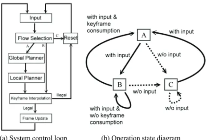
(a) System control loop (b) Operation state diagram Fig. 4 System control loop and operation state diagram
Q, |Q|, is denoted by n and is a system parameter determining the allowable planning time for each frame. Q is comprised of several parallel sub-queues generated in sequence. Q = {Qroot,
Qwaist, Qla, Qra }. According to Fig. 2(b), the global path for the root is generated first and inserted into Qroot. The result will constrain the subsequent local motions generated later. Suppose that m key frames have been created in the buffer and the interval between two key frames is Tinterval. Then the time of key frames available for display becomes m*Tinterval. These key frames in the queue will be consumed at a rate depending on the display efficiency of the machine.
C. System Control Flow
The way we incorporate planning into interactive control is by arranging the planner and the control interface to run alternatively. Fig. 4(a) illustrates the system control operation, in which three different loops (A, B, or C) may be chosen. Loop A is chosen for planning. For a given user input, a global collision-free path for a simplified geometry rooted at the pelvis is computed first. This path is taken as the input to the local motion planner to generate the upper body motions consisting of several key frames stored in the key frame
queue. When the process returns to the branching point, loop B will be chosen to display the planned motion by interpola-tion between two key frames according to the elapsed time. Before the generated motion is sent for display, a collision check is performed again to ensure that the configuration is still valid. If a collision does happen, a key frame is con-sumed, or the queue becomes empty, loop A will be chosen again to generate more key frames. In any cases, if the user stops controlling the interface, loop C will be chosen and the queue will be cleared until the next input comes. We can also define the loops as states in our system and connect them with triggering conditions as shown in Fig. 4(b).
V. LOCAL MOTION PLANNING
A. Search Space: CT-space Roadmap
As pointed out in the previous sections, the search space in the local planning problem is the so-called Configuration Time Space (CT-space). If the activity graph Gx is regarded as
an embedding of Cx, then augmenting the graph with the time
dimension forms the CT-space roadmap, GTx, which is similar to the concept of probabilistic roadmap in C-space. Note that since the root configuration changes over time, the obstacles in the CT-space will also change over time. In addition to the basic requirement of remaining collision-free during the search, a goal is specified by a goal function for each time slice as described in the previous section. Besides, two addi-tional constraints also need to be imposed. First, the search in CT-space needs to be strictly monotonic increasing in time because the time cannot be reversed. Second, we assume that the search proceeds on the connected nodes in the CT-space
roadmap only. Assume that at time ti, the search can move a
configuration qx∈Gx to one of its neighboring nodes, includ-ing the same configuration, in the next time slice, t(i+1). Due to
the maximal velocity constraint and time monotony, the nodes that can be reached from a specific source node form a Di-rected Acyclic Graph (DAG) of depth n, where n is the time span under consideration. We called this reachable region in GTx, GTx-DAG.
(a) (b)
(c) (d)
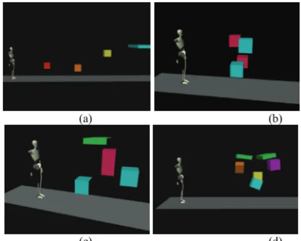
Fig. 6 Experimental scenes for effectiveness testing
Procedure CTRoadmap_Search(s, n) { 1. path ← MakeEmptyPath ( n ); 2. stack ←MakeEmptyStack (); 3. current ← null; 4. desired ← null; 5. t ← 0; 6. Push( s , stack)
7. while (stack is not EMPTY) { 8. current ← Pop(stack); 9. path[current.depth] ← current; 10. if (current.depth = n) 11. return path;
12. t ← GetNextTime(current.depth + 1)
13. desire ← GF(t); // get desired goal for the time slice 14. next ← GetCTN(target); // get all neighbors 15. SortPriority (next, desire); // sort next ascending 16. count ← 0;
17. while( next is not Empty) { 18. candidate ← Pop(next);
19. if (candidate dose not collide at time = t) { 20. count ← count+1; 21. Push(candidate, stack); 22. } 23. } 24. if(count = 0) { 25. new_node ← SearchNewNeighbor(target); 26. if(new_node does not collide at time = t) { 27. Push(new_node , stack); 28. Enhance(); 29. } 30. } 31. } 32. return failure 33. }
B. Search algorithm
For local motion planning, the objective is to find a colli-sion-free path of length n in GTx-DAG. If such a path exists, then there exists a legal local motion for the given global path.
We start the search from the initial node s in GTx-DAG with
the Depth-First Search (DFS) strategy. In any branch during the search, the node with a smaller distance to the configura-tion returned by the goal funcconfigura-tion is chosen as long as it is free. If none of the neighboring nodes is collision-free, the algorithm will first choose to expand the roadmap by adding new neighboring nodes within the region of user-specified radius r and rebuilt the connectivity locally. If this attempt fails as well, the search will backtrack to the unvisited nodes in previous time slides. The search may fail if all avail-able nodes have been visited or a maximal number of nodes have been reached. In this case, the planner will return failure.
The pseudocode of the search algorithm in our local mo-tion planner is shown in Fig. 5. The input to the procedure is a start configuration s and the length of the global path n. We use a stack to store the nodes that has been visited but not ex-panded further in the DFS process. In the main loop, the search pops up the node with the highest time stamp from the stack and explores its neighbors in the next time step. New legal neighbors will be pushed into the stack. If there are no valid neighbors, the system will start a local search (by SeachNewNeighbor procedure) to generate new legal neighbors. If a new neighbor is found, the roadmap will be updated locally with the Enhance routine.
VI. EXPERIMENTAL RESULTS AND DISCUSSION
We have used the Java language to implement the planer. For 3D collision detections, we have used the Java version of the V-Clip package [13]. As for the scene and humanoid mod-els, we have used the X3D/VRML browser implemented in Xj3D for 3D display of the virtual environment. Any avatar models satisfying the H-Anim 200x specification can be used in our virtual environment and controlled by our program. The machine for running the experiments is a P4 2.8G PC with 512MB memory and a NVIDIA FX5200 display card. A. Experiment Design
We have designed four different, yet simple, scenes, as shown in Fig. 6, to test the interactive avatar control proposed in this paper. For each scene, we use different sizes (3-7) of key-frame queues to examine their effects on the efficiency and effectiveness of the local planner. In order to control the
experiment variables in this experiment, we only allow the user to move forward or backward on a path where obstacles are placed along the way on purpose to test how the avatar can avoid these obstacles.
In these four virtual scenes, the difficulty of passing the obstacle areas increases gradually. For example, in scene A, four obstacles are placed sparsely to test the planning of each individual part separately. In scene B, the hand and shoulder will touch the obstacles simultaneously, and we use it to test if the decoupled planner will still work. Scene C is similar to scene B but the obstacles are placed apart with some dis-tances. The purpose of this scene is to test if the system can handle the case where collisions with different parts happen sequentially and with some overlaps. Scene D is the most dif-ficult one since the number of obstacles has been increased to six and they are placed in a way that the space for the avatar to pass through is very limited.
For each of the four scenes, we have done five experi-ments for five different sizes of key frame queues (ranging from 3 to 7), three “walkthrough” tests were performed with different seeds for the random number generator in the plan-ner. In the walkthrough test, the user attempts to control the avatar to pass through the obstacle regions in 30 seconds. If the avatar gets stuck with the obstacles in the way, the user may move the avatar back and forth to try other possible ways to pass the region. If the user cannot pass the region in the given time (30 sec.), the test is regarded as a failure.
During the experiments, two categories of data were corded. The first category contains the data related to end re-sult of how the avatar passes the obstacle regions such as the success rate for passing the regions in 30 seconds, number of successful trials at the first attempt, number of stuck situa-tions, and the time used to pass the region. The second cate-gory includes the total number of the calls to the local motion planner as well as the performance of the planner (real-time or not).
B. Experimental Results
The experimental results reported in Table 1 are taken from the average of successful trials. We use (scene, key frame queue size) to denote a specific experiment. For exam-ple, (A, 4) means the case of using scene A and a key frame queue of size 4. The animation snapshots shown in Fig. 7 are the successful motions generated by the planner for scenes D. Note that for (D, 3) to (D, 7), none of the first trials succeed. In contrast, for scenes A, B, and C, as long as the queue size is larger than 3, the user usually can pass the obstacle region at the first attempt or at a later trial in 30 seconds.
However, for scene D, a key-frame queue of as short as 3 does not yield any successful result. Increasing the queue size will help to increase the successful rate but will also make the performance of the planner no longer real-time (>10fps). In sum, with an appropriate queue size (4-6 in our environment), the obstacle regions for scene A, B, and C can be passed suc-cessfully even if it is not at the first trial.
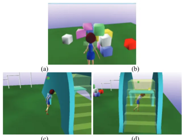
In addition to the four scenes shown in Fig. 7 for doing efficiency experiments, we have also tested the system with some other more realistic scenes. For example, in Fig. 8, we have shown an example scene in a playground. The avatar is under the user’s third person interactive control with a mouse. In the snapshot of Fig. 8(b)-8(d), we can see that the avatar can smartly avoid collisions with various obstacles by generat-ing local motions for the upper-body limbs, such as rotatgenerat-ing or bending waist, in real time. The average frame rate for con-trolling the avatar in this scene is 14.2fps.
VII. CONCLUSIONS
In this paper, we have extended the concept of interac-tive control to a 3D avatar. We have designed a third-person interactive avatar control system based on real-time motion planning techniques. With the help of configuration-time space roadmap, the system is capable of generating the mo-tions for the upper-body limbs to follow some desired motion patterns as well as to avoid environmental obstacles. We be-lieve that this work has pushed the research of real-time mo-tion planning further by providing a good applicamo-tion example that has enhanced the controllability and realism at the same time for intelligent user interface.
ACKNOWLEDGEMENT
This work was partially supported by National Science Council under contract NSC 94-2213-E-004-006.
REFERENCES
[1] G. Arechavaleta, C. Esteves, and J.P. Laumond, “Planning fine motions for a digital factotum,” in Proc. IEEE/RSJ Intl. Conf. on Intelligent
Ro-bots and Systems (IROS’04), pp.822-827, 2004.
[2] M. Chen , S.J. Mountford and A. Sellen, “A Study in Interactive 3D Rotation Using 2D Control Devices,” ACM SIGGRAPH Computer
Graphics, Vol.22, No.4, pp.121-129, 1988
[3] M. Erdmann and T. Lozano-Perez, “On Multiple Moving Objects,” AI Memo No. 883, Artificial Intelligence Laboratory, MIT, 1986.
[4] Y. Koga, K. Kondo, J.J. Kuffner and J.C. Latombe, "Planning Motions with Intentions," in SIGGRAPH '94: Proc. of the 21st Annual Conf. on
Computer Graphics and Interactive Techniques, p.395-408, 1994.
[5] J.J. Kuffner and S.M. LaValle, “RRT-Connect: An Efficient Approach to Sin-gle-Query Path Planning,” in Proc. IEEE Intl. Conf. on Robotics
and Automation, pp.995-1001, 2000.
[6] S.M. LaValle, “Rapidly-Exploring Random Trees: A New Tool for Path Planning,” Technical Report, Computer Science Dept., Iowa State Uni-versity, 1998.
[7] T.Y. Li, and H.K. Ting, “An Intelligent User Interface with Motion Planning for 3D Navigation,” in Proc. of the IEEE Virtual Reality Conf., p.177-184, 2000.
[8] T.Y. Li and H.C. Chou, "Improving Navigation Efficiency with Artifi-cial Force Field," in Proc. of IPPR Conf. on Computer Vision, Graphics,
and Image Processing, 2001.
[9] T.Y. Li, P.F. Chen and P.Z. Huang, "Motion Planning for Humanoid Walking in a Layered Environment." in Proc. of the IEEE Int. Conf. on
Robotics and Automation, pp.3421-3427, 2003.
[10] G. Neilson and D. Olsen, “Direct Manipulation Techniques for 3D Ob-jects Using 2D Locator Devices,” in Proc. of the Workshop on
Interac-tive 3D Graphics, pp.175-182, 1986.
[11] J. Pettre, JP. Laumond and T. Simeon, “A 2-Stages Locomotion Planner for Digital Actors,” in Proc. of the 2003 ACM SIGGRAPH Symp. on
Computer Animation, pp.258-264, 2003.
[12] B. Salomon, M. Garber, M.C. Lin, D. Manocha, “Interactive Navigation in Complex Environments Using Path Planning,” in Proc. of the Symp.
on Interactive 3D Graphics, pp.41-50, 2003.
[13] V-Clip Java port:http://www.cs.ubc.ca/~lloyd/java/vclip.html [14] A. Witkin and Z. Popovic, “Motion Warping,” in Proc. of the 22nd
Annual Conf. on Computer Graphics and Interactive Techniques,
pp.105-108, 1995.
[15] D. Xiao, R. Hubbold, “Navigation Guided by Artificial Force Fields,” in
Proc. of the SIGCHI Conf. on Human Factors in Computing Systems,
pp.179-186, 1998 TABLE I
EXPERIMENTAL DATA ON LOCAL MOTION PLANNER
3 4 5 6 7 3 4 5 6 7 < 30 sec. rate 100% 100% 100% 100% 100% 100% 100% 100% 100% 100% straight rate 0% 100% 100% 100% 100% 0% 100% 100% 100% 100% stuck times 1.3 0.0 0.0 0.0 0.0 12.0 0.0 0.0 0.0 0.0 passed time (sec.) 8.3 5.0 5.0 5.0 5.0 16.7 2.7 2.3 2.3 2.0 Total 40.0 28.0 27.7 26.7 27.0 78.3 15.0 13.7 13.0 12.3 Success rate 79.2% 90.5% 90.4% 90.0% 90.1% 60.9% 84.4% 85.4% 92.3% 100.0% Y Y Y Y Y Y Y Y Y Y 3 4 5 6 7 3 4 5 6 7 < 30 sec. rate 100% 100% 100% 100% 100% 0 67% 33% 67% 100% straight rate 0% 67% 100% 100% 67% 0% 0% 0% 0% stuck times 2.7 0.3 0.0 0.0 0.3 2.5 9.0 1.0 1.3 passed time (sec.) 8.0 3.3 3.3 3.3 9.0 7.5 10.0 12.5 17.3 Total 35.0 18.3 19.3 16.7 15.7 37.5 49.0 26.5 32.3 Success rate 61.9% 69.1% 79.3% 88.0% 95.7% 68.0% 65.3% 84.9% 78.4% Y Y Y Y N Y Y N N C RealTime Performance RealTime Performance Success Local Planning SCENE D SCENE A B
KeyFrame Queue Size
KeyFrame Queue Size Success Local Planning (a) (b) (c) (d)
Fig. 8: Snapshots of the digital actor avoiding collisions with the environ-mental obstacles under interactive user control