DESIGN AND FABRICATION OF A THREE-DIMENSIONAL
LONG-STRETCH MICRO DRIVE BY ELECTROPLATING
Chien-Tai Wu, Wen-Chuan Tai, Chen-Peng Hsu, Wensyang Hsu
Department of Mechanical Engineering National Chiao Tung University
1001 Ta Hsueh Road, Hsinchu, Taiwan, 30010
*[email protected]
ABSTRACT
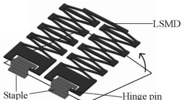
Although lots of works have been devoted to develop the microactuators or microstructures, few researches have been done on three-dimensional microactuators. Here the feasibility investigation on a three-dimensional electro-thermally driven long-stretch micro drive (LSMD) is proposed by integrating the LSMD and mechanical hinge mechanism. The LSMD (about 2000 µm × 500 µm) consists of two cascaded compliant structures in parallel. Each cascaded structure is formed by connecting several basic actuation units in series. The mechanical hinge is used to allow the LSMD to be lifted as a dimensional structure. One of the important issues in fabricating the three-dimensional microactuator is the conducting circuit to actuate the microactuator. Here the Ni electroplating process is used to fabricate the mechanical hinge structure and the LSMD, then the mechanical hinge itself can act as the conductive circuit easily.
From the LSMD simulation results, several design parameters are found to have significant influence on the output displacements. Larger out-stretching displacements are feasible by proper choice of design parameters. Preliminary fabrication results of nickel-made LSMD exhibit output displacement of 190 µm at input voltage of 3 volts. Fabrication results of nickel-made three-dimensional LSMD are also presented.
Keywords: Electro-thermal, three-dimensional, microactuator, hinge, electroplating
1. INTRODUCTION
By using a proper hinge structure, a three-dimensional micro device can be lifted. However most of the lifted MEMS components in previous literatures were microstructures, such as micro mirror [1], micro XYZ stage [2], since the electric connection in a three-dimensional micro sensor or microactuators is still a problem.
For microactuators, a single micro actuator usually can provide only limited output force and displacement. Therefore, proper integration of several basic actuators into an arrayed structure becomes an attractive way to magnify the output. However, lots of arrayed structure designs in microactuators can only magnify either output displacement or output force [3,4,5,6]. Only few published work could achieve magnification on both output force and displacement. The arrayed microactuators to magnify both output displacement and force are often called artificial muscles or muscle-like microactuators. Among these actuators with the silicon-based micromachining techniques, for instance, actuators with arrayed microstructures by electrostatic actuation [7,8] require more complicated fabrication process. In addition, arrayed actuators with electro-thermal actuation [9,10] have been reported with limited output displacements. For non-silicon-based micromachining methods, microactuators driven by piezoelectric [11,12], shape memory effect [13,14], and magnetic actuation principles [15] have been published. However, these non-silicon-based machined actuators were all in the millimeter to centimeter scale and still not feasible in batch fabrication process.
Here the feasibility investigation on a three-dimensional electro-thermally driven long-stretch micro drive (LSMD) is proposed. This design is realized by integrating the mechanical hinge and the LSMD. The LSMD is composed of two cascaded compliant structures in parallel. Each cascaded structure is formed by connecting several basic actuation units in series. When electrical potential is applied, the output displacement and force are generated from the
summation of all basic actuation units in each cascaded structure; therefore it can produce more displacement and force. In this paper the mechanical hinge and LSMD will be made of Ni by electroplating. Therefore, the input voltage can be applied to lift LSMD through metal hinge. Finite element simulation will also be conducted to evaluate the thermal and mechanical behaviors of the LSMD.
NOMENCLATURE
N Number of actuation units in each cascaded structure L Span of actuation beam
W Width of actuation beam T Thickness of Ni LSMD θ Bent beam angle D Width of constraint-bar
2.CONCEPT DESIGN
The concept design of this proposed device is shown in Fig. 1, where the LSMD can be lifted to out-of-plane position with the mechanical hinge structure. Figure 2(a) illustrates the design of the long-stretch micro drive which consists of two cascaded compliant structures in parallel. Each cascaded structure is formed by connecting several basic actuation units (Figure 2(b)) in series. As shown in Fig. 2(a), when electrical current is applied from anchor 1 to anchor 2 to form a close loop, the output displacement and force are generated from the summation of all basic actuation units in each cascaded structure. Since two cascaded structures are in parallel arrangement, the total output force can be doubled. Therefore, more basic actuation units in cascaded structures can effectively magnify the output displacements and forces of the micro drive in compact size. Each basic actuation unit is composed of two V-shaped bent beams (width W, bent angle θ) and one constraint-bar (width D), as shown in Fig. 2(b). When the bent actuation beams are subjected to joule heating, the bent beams expand and lead the actuation unit to stretch outward. It should be noted that the design of the bar is helpful in output magnification, where smaller expansion of the constraint-bar would lead to larger output displacement and force of the micro drive.
Figure 1: Schematic view of the proposed three-dimensional LSMD.
(a) (b)
Figure 2: (a) Design of the long-stretch micro drive (LSMD); (b) Schematic diagram of the basic actuation unit in out-stretching displacement and parameters definitions.
3.FINITE ELEMENT MODELING
Finite element simulations are conducted by using ANSYS 5.5 with electric-thermal analysis (3-D element-69) and thermal-structural analysis (3-D element-45). In preliminary study, the FEM model is constructed without hinge structures. Thermal conduction, convection, and nonlinear structural analysis are considered in the simulations. Therefore, the temperature distributions of the bent actuation beams are not uniform in the analysis. The effects of thermal radiations are not considered here due to the low operating temperatures of the LSMD (below 400°C). The material properties of nickel used in simulation are listed in Table 1.
Table 1. Material properties of nickel used in finite element simulation.
Material Properties Value
Modulus of Elasticity (GPa) 200
Density (Kg/m³) 9040
Coefficient of Thermal Expansion (10−6/ ºC) 12.8
Poisson Ratio 0.31
Thermal Conductivity (W/mK) 90.5 Specific Heat (J/Kg-K) 443.08
Resistivity (nΩ-m) 80
Convection Coefficient (W/m²-K) 50
Figure 3 shows the FEM model of LSMD with five basic actuation units in each cascaded structure. In electric-thermal analyses, electric potentials are applied across contact pad 1 and pad 2. The bottom sides of the contact pads are set as reference temperature to be zero to define thermal boundary conditions. Convection loads are applied on all surfaces of the model with constant convection coefficient value of 50. In nonlinear and large-deflection structural analyses, the bottom sides of the contact pads are fixed. The maximum temperatures of LSMD occur at the connection parts of actuation bent beams. The simulated maximum temperature is limited to below 400ºC. Besides, the maximum stresses are located at the ends of actuation beams attached to contact pads. Figure 4(a) and (b) show the simulated load-deflection curve and maximum temperatures of LSMD, at various input voltages, respectively.
Figure 3: FEM model of the LSMD used in simulations (L=1000 µm, N=5).
(a) (b)
Figure 4: Simulated (a) out-stretching displacements and (b) maximum elevated temperatures of Ni LSMD at various operating voltages.
3.1 Bent Beam Angle θθθθ
Figures 5 shows the steady-state outward displacements of the LSMD with five basic actuation units in each cascaded structure at various bent beam angles θ (0.2°~5.0°) under a constant operating voltage (3 volts). In general, LSMDs can exhibit longer displacements by smaller bent beam angles. However, the bent angles should not to be zero. Besides, small bent beam angles may cause buckling if the structural thickness is not thick enough to provide strong mechanical strength.
Figure 5: Out-stretching displacements of LSMDs (D=30 µm, W=8 µm, T=11 µm) with various bent beam angles at constant applied voltage (3 volts).
3.2 Constraint Bar Width D
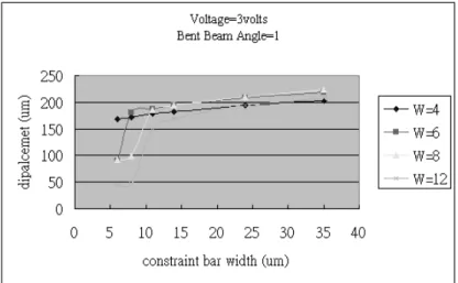
Figures 6 presents the simulated results of constraint-bar width on output displacement. Generally, constraint-bar provides clamping force on both ends of the actuation bent beams. Therefore, elongation of constraint-bar due to thermal expansion will depress output displacements of actuation bent beams. In simulations, it is found that a wider constraint-bar can enhance the output displacements. This is due to lower elevated temperatures of wider constraint-bar. However, wider constraint-bars will consume more thermal power and depress the maximum elevated temperatures that actuation beams can achieve at constant applied voltage. Therefore, constraint-bar width in the range of 25~35 µm is better for electro-thermal LSMD with bent beam widths ranging from 4 to 12 µm. A constraint-bar too wide only get limited improvements in output displacements but required more device area. The width below 15 µm exhibits poorest output displacements and should be avoided in design.
Figure 6: Out-stretching displacements of LSMDs (D=30 µm, θ=1°, W=4~12 µm, T=11 µm) with various constraint-bar widths at constant applied voltage (3 volts).
3.3 Bent Beam Width W
Figure 7 shows the simulated output displacements with various bent beam widths of LSMDs at constant applied voltage. The optimal bent beam width around 8 µm is found at the constant applied voltage mode. For narrower beam widths, the electrical resistances of LSMDs will be higher, therefore it will consume less electrical power and depress output displacements. On the contrary, for wider actuation bent beam, electrical resistances of LSMDs become smaller and get more electrical power, however the mechanical stiffness EI of the bent beams may increase too rapidly and depress output displacements.
Figure 7: Out-stretching displacements of LSMDs (D=30 µm, θ=1°, T=11 µm) under various bent beam widths at constant applied voltage (3 volts).
4. Fabrication process
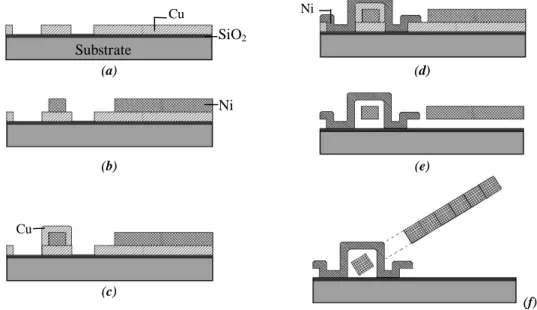
The fabrication process is outlined in Figure 8. First, a 0.5 Ӵm oxide layer is deposited on the wafer as the electrical isolation layer, followed is the 5 Ӵm Cu electroplating of the first sacrificial layer (Fig. 8(a)), and then the 11Ӵm thick Ni layer is electroplated, forming the LSMD and hinge pin (Fig. 8(b)). After that, a 5 Ӵm Cu layer is electroplated as the second sacrificial layer (Fig. 8(c)). Then, the 4Ӵm thickness Ni film is electroplated (Fig.8(d)) to form the staple. The following step is to release the sacrificial layer (Fig. 8(e)) in liquid ammonia with hydrogen peroxide (15 minutes), then followed by a rinse in deionized (DI) water and air drying. The LSMD is lifted up by the probe finally (Fig. 8(f)).
(a) (d)
(b) (e)
(c)
(f) Figure 8. Fabrication Process
Ni SiO2 Substrate Cu Cu Ni
5. PRELIMINARY FABRICATION RESULTS
The electroplating process is used to fabricate the thick LSMDs made of nickel. Owing to the thick electroplated nickel structure, the nickel LSMDs are successfully released by rinsing in IPA solutions and drying on the 120°C hotplate. Figure 9 shows the fabricated 11 µm thick nickel LSMD with 8 µm actuation bent beam width and 6 µm air gap under this. The measured output displacements of LSMDs are shown in Figure 10. The out-stretching displacements can achieve up to 190 µm at input voltage 3 V.
For the three-dimensional LSMD with metal mechanical hinge, Figure 11 shows the whole device before releasing. After releasing, excessive force in the lift-up process by the probe may destroy the cascaded structure as shown in Figure 12. Concerning the hinge part, Figure 13 and Figure 14 show the released SEM of the staple and the released mechanical hinge mechanism. It is observed that the 11 µm thick plates can be lifted up at about 90 degrees. At next step, LSMD and hinge mechanism will be integrated entirely.
(a) Before activation (b) After activation
Figure 9: The preliminarily fabricated 11 µm thick nickel LSMD with stretching displacements up to 190 µm at 3 volts (L=1000 µm, N=5,W=8 µm, D=30 µm)
0 1 2 3
Applied Voltage (Volts)
0.0 40.0 80.0 120.0 160.0 200.0 Disp lac e m e n ts ( m )
Bent Beam Width = 8um Bent Beam Angle = 1 Constraning Bar Width = 30 um L= 1000 um, N= 5
Figure 11: The three-dimensional LSMD before releasing. Figure 12: Lifted LSMD with hinge mechanism
Figure 13: The staple of hinge. Figure 14: Lifted microstructures with hinge mechanism.
6.CONCLUSIONS
The design, fabrication and finite element analysis of a three-dimensional electro-thermally driven long-stretch micro drive (LSMD) is proposed by integrating the LSMD and mechanical hinge, several design parameters, including bent beam angle, width of actuation beams, and constraining bar width as found to have strong influences on the output performances of the LSMD. So the metal-based surface micro machining has technique shown to be able to fabrication the LSMD and hinge mechanism successfully. Preliminary fabrication results of nickel-made LSMD exhibit output displacement of 190 µm at input voltage of 3 volts. Through the mechanical hinge made of nickel, the LSMD is possible to be a three-dimensional device with mobility in out-of-plane direction
ACKNOWLEDGMENTS
This work is supported by the National Science Council (Taiwan) under Grant NSC 90-2212-E-009-033. Authors also would like to express their appreciation to the SRC of National Chiao Tung University (Taiwan) for providing some fabrication facilities.
REFERENCES
1. Reid, J.R., Bright, V.M., Butler, J.T., ”Automated assembly of flip-up micromirrors” Sensors and Actuators A, 66, pp. 292-298, 1998.
2. Fan, L., Wu, M.C., Choquette, K.D., Crawford M.H.,”Self-Assembled Microactuated XYZ stages for optical Scanning and Alignment,”TRANSDUCERS’97 pp.16-19, June 1997.
3. Tang, W.C., Chong, T.U., Nguyen, H. and Howe, R.T., “ Laterally driven polysilicon resonant microstructures,”
Sensors and Actuators A, 20, pp. 25-32, 1989.
4. Comtois, J. and Bright, M., “ Surface micromachined polysilicon thermal actuator arrays and applications,” 7th
IEEE Solid State Sensor and Actuator Workshop (Hilton Head Island, SC, June 1996), pp. 174-7, 1996.
5. Chu, Larry L., Hetrick, Joel A. and Gianchandani, Y. B., “ Compliant microtransmissions for rectilinear electrothermal actuators,” Tranducers’01, Eurosensors XV, 11th International Conference on Solid-State Sensors and Actuators, Munich, Germany, 2001.
6. Park, J.S., Chu, L.L., Oliver, A.D. and Gianchandani, Y. B.,” Bent-beam electrothermal actuators---part II: linear and rotary microengines,” J. Microelectromechanical systems, Vol. 10, No. 2, pp.255-62, June 2001.
7. Esashi, M., Yamaguchi, M., Kawamura, S. and Minami, K., “ Control of distributed electrostatic microstructures,”
J. Micromech. Microeng., Vol. 3, pp.90-95, 1993.
8. Yadon, L.N., Jacobson, J.D., Goodwin-Johansson, S.H., Bobbio, S.M. and Bartlett, C.A., “ Integrated force arrays: theory and modeling of static operation,” J. Microelectromechanical systems, Vol. 4, No. 3, September 1995 9. Judy, J. W., Tamagawa, T. and Polla, D. L., “ Surface micromachined linear thermal microactuator,” Proc. IEEE
pp. 629-632, 1990
10. Ananthasuresh, G.K. and Moulton, T., “ Micromechanical devices with embedded electro-thermal-compliant actuation,” Sensors and Actuators A, 90, pp.38-48, 2001
11. Claeyssen, F. and Letty, R.L., “ Piezoactuators and piezo motors for high strokes/precise positioning applications,”
Proc. Actuator 98 Conf., Pub Messe Bremen, Germany, pp. 170-73, 1998.
12. Claeyssen, F., Letty, R.L., Barillot, F., Lhermet, N., Fabbro, H., Guay, P. and Yorck, M., “ Mechanisms based on piezo actuators,” Proc. Actuator 2000 Conf., Pub Messe Bremen, Germany, pp. 456-59, 2000.
13. Mineta, T., Mitsui, T., Watanabe, Y., Kobayashi, S., Haga, Y. and Esashi, M., “ Batch fabricated flat meandering shape memory alloy actuator for active catheter,” Sensors and Actuators A, 88, pp. 112-120, 2001.
14. Kohl, M. and Skrobanek, K.D., “ Linear microactuators based on shape memory effect,” Sensors and Actuators A, 70, pp. 104-11, 1998.
15. Frank, T. and Schilling, C., “ The development of cascadable microdrives with muscle-like operating behaviour,”