高效能且可組態之子字組平行化乘加器設計
99
0
0
全文
(2) 高效能且可組態之 子字組平行化乘加器設計 High-Performance Reconfigurable Sub-Word Parallel Multiplier-Accumulator Design. 研 究 生:林宏光. Student: Hung-Kuang Lin. 指導教授:黃俊達 博士. Advisor: Dr. Juinn-Dar Huang. 國立交通大學 電子工程學系. 電子研究所. 碩士論文. A Thesis Submitted to Department of Electronics Engineering & Institute of Electronics College of Electrical & Computer Engineering National Chiao Tung University in partial Fulfillment of the Requirements for the Degree of Master in Electronics Engineering & Institute of Electronics July 2006 Hsinchu, Taiwan, Republic of China. 中華民國九十五年七月.
(3) 高效能且可組態之 子字組平行化乘加器設計 研究生:林宏光. 指導教授:黃俊達 博士. 國立交通大學 電子工程學系. 摘. 電子研究所. 要. 本論文提出一個高效能乘加器的設計方法。此乘加器除支援子字 組平行化功能之外,還能執行混模運算並具較有彈性的子字組設定。 我們提出了一個新的子字平行部份乘積陣列及一個創新的子字平行 部份乘積簡化樹以實現子字組平行化。為了利用原本的乘加器硬體, 子字組平行化乘加器僅需增加微量的延遲及些許的面積。我們提出的 乘加器可動態重組、可合成、可重覆使用且可驗證。我們實做並比較 我們的設計及先前的設計。實驗數據顯示,無論在設計延遲、所佔面 積、所耗功率,我們的方法在理論上及實務上都改善並且勝過舊方法。. I.
(4) High-Performance Reconfigurable Sub-Word Parallel Multiplier-Accumulator Design. Student: Hung-Kuang Lin. Advisor: Dr. Juinn-Dar Huang. Department of Electronics Engineering & Institute of Electronics National Chiao Tung University. ABSTRACT This thesis presents the design methodology of a high-performance reconfigurable multiplier-accumulator (MAC) capable of supporting sub-word parallelism (SWP) and additional features such as mixed-mode operation and flexible sub-word combination and mode assignment scheme. In order to perform SWP on the proposed scalar MAC, a new SWP partial product array and a novel speed-optimized SWP partial product reduction tree are proposed. With slight delay and some area overhead, the SWP MAC utilizes essentially the same hardware as the proposed scalar MAC. The whole design is dynamically reconfigurable, fully-synthesizable, reusable, and verifiable. The proposed designs and previous relevant works are implemented and compared. Experimental results demonstrate that the proposed SWP MAC design theoretically and practically improves and outperforms previous works in terms of critical path delay, area cost, and power consumption.. II.
(5) ACKNOWLEDGMENT 誌. 謝. 能完成這份論文,首先我要感謝指導教授黃俊達老師。老師除 了授業及解惑專業知識之外,也教導我許多做研究及做事的方法與態 度,這些都對我的未來有裨益。另外感謝 ACAR 實驗室同學翊展、 孝恩、維聖、士祐,你們在各方面給的建議與幫助讓我這兩年研究生 涯過得充實而不孤單;碩一學弟哲霖、之暉、南興,碩一點五吉祥物 詠翔學長,你們是阿達實驗室的快樂泉源,謝謝你們讓我愛上 LAB317B 這小空間;特別感謝碩零學弟建德在這個研究議題上給我 的大量支援。謝謝交大電子 92 級的老同學們在工作上給的建言;謝 謝建中 329 班及蘆中 326 的一干老朋友們,看到大家都很努力讓見賢 思齊。也向其他默默支持我的朋友們說聲感謝。謝謝遠在美國的文玉 長時間的擔待,妳的支持是我的最大動力。最後且最重要地,感謝家 人的關懷。爺爺及奶媽是我的精神支柱;姊姊一直以來的支持及鼓 勵,讓我一生受用;感謝父母親二十多年來的撫養及付出,沒有您們 就不會有我與這份論文,我會努力讓您們開心。 我願將這份論文獻給支持我的大家。我愛你們!. III.
(6) CONTENTS Abstract (Chinese) .................................................................................. I Abstract (English) ................................................................................. II Acknowledgment ................................................................................. III Contents ................................................................................................ IV List of Tables ...................................................................................... VII List of Figures ................................................................................... VIII Chapter 1. Introduction ....................................................................... 1. Chapter 2. Previous Works ................................................................. 4. 2.0 Overview ……………………………………………………………………… 4 2.1 Prerequisites …………………………………………………………………... 4 2.1.1 Simple Multiplication & Booth's Algorithm ………………………...….... 4 2.1.2 Acceleration of Multiplication Flow ………………………………....…... 6 2.1.3 Modified Booth's Algorithm (MBA) ………………………………..….... 7 2.2 Related Works ……………………………………………………………...…. 9 2.2.1 Partial Product Generation (PPG) …………………………………...….... 9 2.2.2 Three-Dimensional-Method (TDM) PPRT …………………………...… 14 2.2.3 High-Speed Adders ……………………………………………………... 16 2.2.4 Sub-Word Parallelism (SWP) …………………………………………... 20 2.3 Summaries of Previous Works …………………………………………….… 26. IV.
(7) Chapter 3. Proposed MAC Designs .................................................. 27. 3.0 Overview ……………………………………………………….………...….. 27 3.1 Scalar MAC (SMAC) Design ……………………………………………..… 27 3.1.0 Specification ………………………………………………………….… 27 3.1.1 Scalar Partial Product Generation (SPPG) …………………………...…. 28 3.1.2 Scalar Partial Product Reduction Tree (SPPRT) …………………….….. 31 3.1.3 Scalar Carry-Propagate Adder (SCPA) ……………………………….… 33 3.1.4 Summaries of the Proposed Scalar MAC Design …………………….. 33 3.2 Sub-Word Parallel MAC (SWP MAC) Design………………….…………… 34 3.2.0 Specification ……………………………………………….…………… 34 3.2.1 Sub-Word Parallel MAC Execution Flow ……………………………… 35 3.2.2 Sub-Word Parallel PPG (SWPPG) ……………………………………… 36 3.2.3 Sub-Word Parallel PPRT (SWPPRT) …………………………………… 43 3.2.4 Sub-Word Parallel CPA (SWCPA) ……………………………………… 46 3.2.5 Summaries of the Proposed SWP MAC Design ...……………………… 49. Chapter 4. Experimental Results ...................................................... 50. 4.0 Overview …………………………………………………………………...... 50 4.1 Implementation …………………………………………..………………….. 50 4.2 Discussion of Experimental Results ………………………………………… 51 4.2.0 Overview ………………………….…………………………………….. 51 4.2.1 Delay Comparison ………………………………...….………………… 52 4.2.2 Area Comparison …………………………………….…………………. 55 4.2.3 Power Comparison …………………………………...…………………. 58. V.
(8) Chapter 5. Application Notes ............................................................ 60. 5.0 Overview ………………………………………………………………… 60 5.1 Functionality Enhancement ………………………………….……………… 60 5.1.1 Multiply-Accumulate (MAC) Operation ………………….……………. 60 5.1.2 Multiply-Negate (MAN) Operation ………………………..…………… 62 5.1.3 Unsigned Operation ………………………………………….….……… 65 5.1.4 Mixed-Mode Operation ……….……………………………...………… 67 5.2 Overflow/Underflow Check for FXP Numbers …………………...………… 69 5.2.1 Fixed-Point (FXP) Representation ……………………………………… 69 5.2.2 Maintaining Precision & Accuracy …………………………...………… 70 5.2.3 Saturation & Overflow/Underflow for Integers ………………………… 71 5.2.4 Rounding of Fractions …………………………………………….…..… 77 5.3 Reconfigurable Parameters Setup …………………………………....……… 78. Chapter 6. Conclusions ...................................................................... 82. Future Works ........................................................................................ 83 Bibliography ......................................................................................... 84. VI.
(9) LIST OF TABLES Table 2.1. Selection table of modified Booth’s algorithm ………………....………... 8 Table 2.2. Truth table of standard encoding …………………………….......…….... 10 Table 2.3. Truth table of compact encoding …………………………....................... 10 Table 2.4. Truth table of race-free encoding ……………………….....................…. 11 Table 2.5. Truth table of LSB_new and hot2 …………………..…………............… 14 Table 3.1. Specification of the proposed SMAC design ………………................… 27 Table 3.2. Specification of the proposed SWP MAC design ………….....………… 35 Table 3.3. Possible sub-word combinations of the proposed SWP MAC design ...... 35 Table 3.4. Truth table of sign encoding bits and sign bits of PPs ………………..… 41 Table 4.1. Environment setup for experiments …………………………………..… 51 Table 4.2. Critical path delay comparison ……………………………………….… 52 Table 4.3. Delay overhead on performing SWP …………………………………… 54 Table 4.4. Area cost comparison …………………………………………………… 55 Table 4.5. Area overhead on performing SWP ………………………………..…… 57 Table 4.6. Power consumption comparison ………………………………………... 58 Table 4.7. Power-delay characteristic comparison …………………………….…… 59 Table 5.1. Pseudo MAC instruction types and notations ………………………...… 72 Table 5.2. Pseudo MAC instruction examples ……………………………………... 72 Table 5.3. Some available modes for pseudo MAC instructions …………………... 73 Table 5.4. Possible saturation conditions using the exampling architecture ………. 76 Table 5.5. Interface of the proposed design ………………………………………... 79 Table 5.6. Possible sub-word combinations of the proposed SWP MAC design ….. 80 Table 5.7. Configuration example of KILL signal ……………………………….... 80 Table 5.8. Configuration example of MODE signal ……………………………….. 81 VII.
(10) LIST OF FIGURES Fig. 2.1. Simple multiplication flow ………………………………………………… 5 Fig. 2.2. Multiplication flow in three steps ………………………………………….. 7 Fig. 2.3. Execution flow of MBE multiplication ……………………...…………….. 9 Fig. 2.4. The MBE encoder and decoder in [9] ………………………….................. 11 Fig. 2.5. Sign encoding and hot-one modification …………………………………. 13 Fig. 2.6. The concept of TDM ……………………...……………………………… 15 Fig. 2.7. An 8-bit carry-select adder example ……………………………………… 17 Fig. 2.8. Architecture of a 32-bit hybrid parallel-prefix/carry-select Ling adder ….. 18 Fig. 2.9. Architecture of a 32-bit scalar Fong adder ……………………………….. 19 Fig. 2.10. Logic operators used in Fong adder …………………………………….. 20 Fig. 2.11. A simplified PPA for 32 × 32 multiplication in different modes ………... 22 Fig. 2.12. Shared Segmentation PPA for 32×32 multiplication in different modes ... 24 Fig. 3.1. Execution flow of the proposed Scalar MAC design …………………….. 28 Fig. 3.2. Decoding mcand 1000 in different modes when MBE selects -2x ……….. 30 Fig. 3.3. FA cell used in the proposed SPPRT …………………………………… 32 Fig. 3.4. The proposed scalar architecture …………………………………………. 34 Fig. 3.5. Execution flow of the 32-bit proposed SWP MAC design ……………….. 36 Fig. 3.6. A 32-bit example of masking and multiplexing on the multiplier ……....... 37 Fig. 3.7. Detailed view of the 32-bit proposed SWPPA with a selection example … 39 Fig. 3.8. SW combinations of the 32-bit proposed SWP MAC design …………….. 42 Fig. 3.9. Breaking the FA carry-chain for SWP in SWPPRT ………………………. 44 Fig. 3.10. FA with carry-in masking used in [10] ………………………………….. 45 Fig. 3.11. FA with carry-out masking used in the proposed design ………………... 45 Fig. 3.12. A simple 64-bit SWP adder ……………………………………………… 47 VIII.
(11) Fig. 3.13. Architecture of a 32-bit Fong adder with reconfigurability ……………... 48 Fig. 5.1. Execution flow of two approaches to completing MAC operation ………. 61 Fig. 5.2. MAN flow of method A …………………………………………………... 62 Fig. 5.3. MAN flow of method B …...……………………………………………… 63 Fig. 5.4. MAN flow of method C …………………………………………………... 64 Fig. 5.5. An exampling PPA for MAN/MAS operations using method C …………. 65 Fig. 5.6. Adding a PP to perform unsigned operation ……………………………… 66 Fig. 5.7. A representation problem on negation of unsigned numbers …………….. 67 Fig. 5.8. Dynamic range comparison among signed, unsigned, and mixed-mode … 68 Fig. 5.9. A PPA supporting MAN/MAS, unsigned/mixed-mode operation ………... 69 Fig. 5.10. Effect with or without saturation when overflow/underflow occurs ……. 74 Fig. 5.11. Three different rounding schemes ………………………………………. 78. IX.
(12) CHAPTER 1 INTRODUCTION Multiply-accumulate (MAC) computation is one of the most frequent operations in DSP applications. A multiplier followed by an accumulator to integrate into a multiplier-accumulator (MAC) unit characterizes a DSP processor. A series of MAC operations has an arithmetic form like coefficient-data, inner product, or matrix computation, and which serves as the core operation in many DSP algorithms such as convolution, finite impulse response (FIR), fast Fourier transform (FFT), discrete cosine transform (DCT), and so many other DSP algorithms also demand extensive MAC operations. Multiplication (MUL), a basic essential arithmetic operation, is regarded as a special case of MAC operation processed in the same MAC unit [1], [2], [3]. Improvements in MAC design therefore significantly benefit the performance of the whole DSP processor according to Amdahl’s law. A high performance DSP processor desires a high speed MAC unit with reduced area, low power, and high computational throughput, decided by the specification. To facilitate a high speed MAC design, an architecture using radix-4 modified Booth encoding (MBE) [4] and Wallace partial product reduction tree (PPRT) [5] associated with a high speed carry-propagate adder (CPA) is prevalent. To increase the computational throughput, sub-word parallelism (SWP), a form of single-instruction-multiple-data (SIMD), helps by processing all sub-words (SWs) in parallel and hence providing a performance boost especially for multimedia applications that often require lower-precision operands [6]. Considering the short time to market of a product required in the very era of system-on-a-chip (SoC), a synthesizable, reusable, and verifiable silicon intellectual 1.
(13) property (SIP) with flexible user reconfigurability is popular and utilizes the design reuse concept to help accelerate system integration [7]. Some MAC designs improve the delay of CPA by prudently calculating the signal arrival time of each operand bit, and use the delay profile to configure a faster adder scheme [8], [9]. This indicates the adder scheme highly depends on the chosen cell library and thus usually not suitable for reusable designs. The previous SWP MAC designs are not speed optimized: the architecture in [6] does not use MBE, resulting more partial products to be accumulated and considerably increasing the latency. A modified Booth-encoded (MBE) MAC architecture in [10], [11] completes SWP using a technique called “shared segmentation” to arrange the partial product array (PPA); however, it forces a regular connection scheme for full-adders (FAs) in the Wallace PPRT, producing lower performance. In addition, the previous designs have a limited functionality either in data format or in SW flexibility. This thesis presents a synthesizable, reusable, and verifiable high-performance reconfigurable MAC design. The proposed SWP MAC design is obtained, with slight effort and small area overhead, by performing SWP on the proposed scalar design which comprises a high performance MBE, a speed optimized PPRT, and a high speed CPA. The proposed scalar design supports not only the signed operation but also the unsigned and a special mixed-mode operation which forces the multiplicand to be signed and multiplier to be unsigned. Mixed-mode operation provides a larger dynamic range for DSP applications. The proposed scalar design also has better performance in most cases compared with previous scalar MAC designs. As for SWP, the proposed SWP MAC utilizes a novel SWP PPA to advance the performance of SWP PPRT, and takes advantage of a new concept of carry-out masking to facilitate a speed optimized SWP PPRT. Concerning the CPA, a high-performance Fong adder 2.
(14) with SWP capability is integrated into the proposed scalar and SWP designs. The proposed scalar design is superior to related works in most cases while the proposed SWP MAC design not only outperforms previous works in terms of delay, area, and power consumption but also features a more flexible SW combination and mode assignment scheme. The remainder of this thesis is organized as follows: Chapter 2 briefly describes the previous works that are most relevant to the proposed designs. Chapter 3 details the design methodology of the proposed MAC designs and theoretically compares with previous works. Chapter 4 demonstrates and discusses the experimental results. Chapter 5 explains some important application notes concerning the utilization of the proposed designs. Chapter 6 concludes this thesis. Future works and bibliography are also provided afterward.. 3.
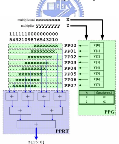
(15) CHAPTER 2 PREVIOUS WORKS 2.0 Overview In this chapter, we review some important previous work relevant to the proposed MAC architecture. Section 2.1 recalls fundamentals and algorithms of multiplication; Section 2.2 concisely describes some related works, theorems, and techniques; Section 2.3 summarizes the previous works and highlights the differences to be described in the next chapter.. 2.1 Prerequisites 2.1.1 Simple Multiplication & Booth’s Algorithm Traditional binary multiplication flow is essentially the same as done in decimal multiplication: Logic AND operation is performed on a single bit of the multiplier with each bit of multiplicands; the temporal result, a partial product (PP), always equals the multiplicand itself or zero; the least-significant-bit (LSB) of the PP is aligned to the multiplier bit used. Consequently, if an m-bit by n-bit multiplication is executed, there will be n PPs each with m significant bits. After zero-extending or sign-extending each PP to the most and the least significant ends, an m-bit by n-bit rectangular partial product array (PPA) is formed. Accumulating all PPs produces the final multiplication result. Fig. 2.1 shows the simple multiplication flow of an 8-bit by 8-bit multiplication. Roughly speaking, the number of the significant bits used (x-bit in PPA of Fig. 2.1) is proportional to the amount of hardware required [12].. 4.
(16) The flow above is somewhat redundant when a series of zeros shows in the multiplier; it can be further improved. In 1951, Booth introduces a binary multiplication algorithm on the grounds of the add-and-shift concept [12]: the consecutive bits in multiplier affect the generation of partial products. This algorithm is based on two’s complement system and thus performs signed multiplication. The fact that shifting alone is faster than addition followed by shifting makes Booth’s multiplication faster than traditional ones. Although Booth’s algorithm, also referred as radix-2 Booth’s algorithm, is not directly applied to modern arithmetic circuits, it serves as a basis in understanding the radix-4 version of this algorithm – modified Booth’s algorithm (MBA) [3]. Note that both simple multiplication and Booth’s algorithm produce a number of n PPs where n is the bit width of the multiplier, as the eight PPs shown in Fig. 2.1.. Fig. 2.1. Simple multiplication flow.. 5.
(17) 2.1.2 Acceleration of Multiplication Flow The completion of multiplication involves two basic operations – partial product generation (PPG) and their accumulation. Consequently, reducing the number of PPs or accelerating their accumulation helps speed up multiplication [1]. The MBA for reducing the number of PPs will be detailed in the next section. Accumulation of all PPs implies a series of addition. In theory, we can use a series of carry-propagate adders (CPAs) to accumulate all PPs; the number of addition required is in proportion to the number of PPs. This naïve method is impractical because the delay of a CPA is considerable, let alone the number of PPs grows with the bit width of the multiplier. A better architecture for connecting CPAs exploits some parallelism; this is how we demonstrate in Fig. 2.1. However, the number of the CPA levels still relates to the number of the PPs, incurring longer delay. As a result, the partial product reduction tree (PPRT) is often utilized. There are plenty of algorithms dedicating to construct a PPRT [5], [14], [15]. One of the most popular constructions of PPRT is the Wallace Tree [5]: use full-adders (FAs), or say (3:2) counters [3], as the building blocks to perform carry-save addition (CSA). It does not work out the addition result at the middle levels of the tree; instead, it just saves each level’s carry-out and sum information of CSAs, avoiding the carry propagation which takes a long time. A PPRT, Wallace Tree included, often reduces many rows of PPs until only two rows remain; after summing these two final PPs using a CPA (carry-out demands 1-bit left shift), the product is obtained. A PPRT speeds up multiplication; multiplication flow is hence frequently sliced into three phases – partial product generation, partial product reduction tree, and carry-propagate adder. Fig. 2.2 exhibits the flow.. 6.
(18) Fig. 2.2. Multiplication flow in three steps.. 2.1.3 Modified Booth’s Algorithm (MBA) As mentioned previously, the PPG is dependent with the pattern of multiplier, and the number of PPs is in proportion to the bit width of the multiplier. A PPG that creates a fewer number of PPs will allow the partial product summation to be faster and use less hardware. Given an n-bit multiplier, simple multiplication or Booth’s algorithm encodes and ignores/eliminates one multiplier bit for n times, and hence obtains n PPs. In 1961, MacSorley presents a radix-4 Booth’s algorithm based on the concept of original Booth’s algorithm and is refereed to as modified Booth algorithm (MBA) [4]. Due to the property of radix-4 system, two bits of multiplier are ignored after each encoding, and hence the number of PPs is reduced. Thanks to the property, 7.
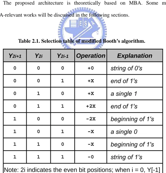
(19) modified Booth’s encoding (MBE) generates fewer PPs, and is especially useful if groups of consecutive zeros and ones shown in the multiplier. Table 2.1 lists the corresponding behavior for all possible conditions of an encoding triplet [1]. MBA decreases the latency of multiplication through reduction of the number of the PPs and thus the reduction of the levels in the PPRT. A modified Booth encoded/recoded (we use “encode” in the remaining content) multiplier also consists of three parts: a modified Booth encoder (MBE) associated with the arrangement/alignment of partial product array (PPA) to do PPG, a lower PPRT to accumulate PPs to two, and a fast CPA to sum for the product. Fig. 2.3 displays the execution flow of modified Booth encoded multiplication. The proposed architecture is theoretically based on MBA. Some most MBA-relevant works will be discussed in the following sections.. Table 2.1. Selection table of modified Booth’s algorithm.. Y2i+1. Y2i. Y2i-1. Operation. Explanation. 0. 0. 0. +0. string of 0's. 0. 0. 1. +X. end of 1's. 0. 1. 0. +X. a single 1. 0. 1. 1. +2X. end of 1's. 1. 0. 0. -2X. beginning of 1's. 1. 0. 1. -X. a single 0. 1. 1. 0. -X. beginning of 1's. 1. 1. 1. -0. string of 1's. Note: 2i indicates the even bit positions; when i = 0, Y[-1] is assume to be zero 8.
(20) Fig. 2.3. Execution flow of MBE multiplication.. 2.2 Related Works 2.2.1 Partial Product Generation (PPG) Partial product generation is divided into two parts - decoding the multiplicand in correspondence with the encoding of multiplier done by an MBE, and the arrangement and alignment on the MBE outputs to form the PPA. Concerning the MBE, [16] presents a comparison of energy dissipation among standard, compact, and race-free encoding schemes of an MBE. The race-free. 9.
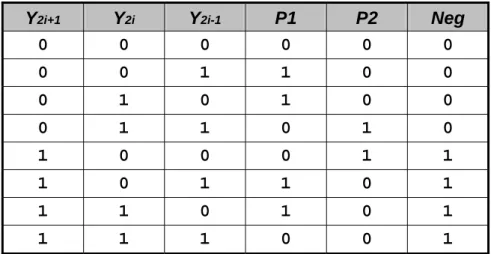
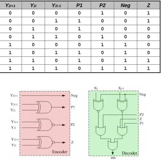
(21) scheme encoded MBE consumes least power because it balances the delay of internal signals and thus avoids glitches/sparks in the circuits. In [9] the race-free MBE is further optimized in terms of timing and area. The spirit of this implementation is to intentionally use “wrong” encoding signals at middle gate levels and corrects the error at final level. The temporal “wrong” logic enables more logic optimization compared to other encoding schemes, leading to a decrease in delay, reduction of area, and less consumption of power. Table 2.2, 2.3, and 2.4 list the truth table of standard, compact, and race-free MBE schemes, respectively. Fig. 2.4 shows the improved encoder and decoder of the MBE in [9]. Table 2.2. Truth table of standard encoding. Y2i+1 0. Y2i 0. Y2i-1 0. P1 0. P2 0. Z 1. M1 0. M2 0. 0. 0. 1. 1. 0. 0. 0. 0. 0. 1. 0. 1. 0. 0. 0. 0. 0. 1. 1. 0. 1. 0. 0. 0. 1. 0. 0. 0. 0. 0. 0. 1. 1. 0. 1. 0. 0. 0. 1. 0. 1. 1. 0. 0. 0. 0. 1. 0. 1. 1. 1. 0. 0. 1. 0. 0. Table 2.3. Truth table of compact encoding. Y2i+1 0. Y2i 0. Y2i-1 0. P1 0. P2 0. Neg 0. 0. 0. 1. 1. 0. 0. 0. 1. 0. 1. 0. 0. 0. 1. 1. 0. 1. 0. 1. 0. 0. 0. 1. 1. 1. 0. 1. 1. 0. 1. 1. 1. 0. 1. 0. 1. 1. 1. 1. 0. 0. 1. 10.
(22) Table 2.4. Truth table of race-free encoding. Y2i+1 0. Y2i 0. Y2i-1 0. P1 0. P2 1. Neg 0. Z 1. 0. 0. 1. 1. 0. 0. 1. 0. 1. 0. 1. 0. 0. 0. 0. 1. 1. 0. 1. 0. 0. 1. 0. 0. 0. 1. 1. 0. 1. 0. 1. 1. 0. 1. 0. 1. 1. 0. 1. 0. 1. 1. 1. 1. 1. 0. 1. 1. 1. Fig. 2.4. The MBE encoder and decoder in [9].. When MBA is used, the PPs are treated as signed numbers since three negative MBE outputs may be selected as listed in Table 2.1. This suggests sign extension be applied to every PP to ensure a correct result; however, sign extension needs to take considerable extra logic. To deal with, in [17], [18], [19], a technique called sign-encoding (SE) or sign-generation is provided and [12] gives this technique a general description. The concept of SE is depicted in Fig. 2.5 at the MSB end: It begins to presume all PPs are negative and hence one-extension is applied as shown in Fig. 2.5a. Since the extended ones are fixed in position, accumulating all extended 11.
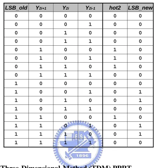
(23) ones in advance produces {1,1} in front of the first PP and {1,0} for others, as shown in Fig. 2.5b. To correct the presumption, add one to the LSB of each sign-extension string, resulting in the logic in Fig. 2.5c. As a whole, SE exploits the predictability of sign-extension, and cleverly protects from the redundant extension bits simply for correctly representing a sign number. It takes only two or three SE bits, {p,n,n} for the first PP and {1,p} for others, in front of the original MSB of each PP where n stands for the original sign of each PP; p, the negation of n. We simulate a multiplier with or without using SE. While SE is used, the power consumption of the PPG and PPRT is saved up to one-third of that without using SE; the improvment rate grows as the bit width increases. Another problem arises when MBE selects a negative output. Since MBA treats the operands as signed numbers in two’s complement (TC) format, if a negative output is selected, we have to negate/two’s-complement the bit stream, implying a two’s complementer for negation is required. To complete the operation, the ones, also called hot-ones [19], are needed to be added after inverting (one’s complementing) the bit stream. It’s a waste to let these ones solely for TC be one of the PPRT inputs. Fortunately, due to MBA this can be prevented since the least significant bit (LSB) position of the present PP should align two bits far from the LSB of the preceding PP; two bits space {h,h} is saved and can be utilized to locate the hot-one from the preceding PP as shown in Fig. 2.5a at the LSB end. The hot-one may also left shift one bit if MBE selects 2x or -2x from the encoding table, but this takes no effort since two bits space are reserved. In case a random-valued multiplier is being encoded, the hot-one bit may show up in either left or right h position. This irregularity will increase the PPRT latency [9]. In [9], the authors also propose a skill – we refer it to “hot-one modification” in this paper– to regulate the LSB end of all PPs. Observing the fact that the hot-one 12.
(24) logic relates the LSB logic of the present PP as shown in Fig. 2.5b, a truth table as listed in Table 2.5 can be built; the new logic equation of two signals LSB_new and hot2 can be expressed as:. LSB _ newi = xLSB ⋅ ( y 2 i − 1 ⊕ y 2 i ) hot 2 = y 2 i + 1 ⋅ y 2 i - 1 + y 2 i ⋅ y 2 i − 1 + xLSB ⋅ y 2 i + xLSB .. (2.1). It arranges all hot-one bits to the left h positions (hot2) accompanied with the probable modification on the preceding LSB (LSB_new). As a result, Fig. 2.5c exhibits the arranged, shorter, parallelogram-shaped, more regular PPA to be accumulated in the PPRT.. Fig. 2.5. Sign encoding and hot-one modification. 13.
(25) Table 2.5. Truth table of LSB_new and hot2. LSB_old 0. Y2i+1 0. Y2i 0. Y2i-1 0. hot2 0. LSB_new 0. 0. 0. 0. 1. 0. 0. 0. 0. 1. 0. 0. 0. 0. 0. 1. 1. 0. 0. 0. 1. 0. 0. 1. 0. 0. 1. 0. 1. 1. 0. 0. 1. 1. 0. 1. 0. 0. 1. 1. 1. 0. 0. 1. 0. 0. 0. 0. 0. 1. 0. 0. 1. 0. 1. 1. 0. 1. 0. 0. 1. 1. 0. 1. 1. 0. 0. 1. 1. 0. 0. 1. 0. 1. 1. 0. 1. 0. 1. 1. 1. 1. 0. 0. 1. 1. 1. 1. 1. 0. 0. 2.2.2 Three-Dimensional-Method (TDM) PPRT In [8], Oklobdzija et al present a three-dimensional method (TDM) to build a speed optimized Wallace PPRT. The main idea of this speed optimization can be briefly depicted as Fig. 2.6: In Fig. 2.6a, a common logic implementation of an FA is shown. Without loss of generality, assuming a NAND gate delay to be 1 and an XOR gate delay to be 2, the delay of each input-to-output path can be calculated as shown in Fig. 2.6b. The longest path is from input a or input b to output sum; sum, therefore, is referred to as the “slow output” in contrast with the “fast output”, cout. cin is the “slow input” since it can wait for a slow output. Connecting a “slow output” to a signal requiring a “fast input” (e.g., a) produces the critical path! Take a two-level PPRT for example, the latency of the left configuration in Fig. 2.6c is. 14.
(26) more balanced since it connects the “fast output” cout to a “fast input” b, while the regular configuration on the right side always connects sum to b, creating a critical path. Exploiting the concept to balance the uneven delay of all paths is the spirit of TDM.. Fig. 2.6. The concept of TDM.. 15.
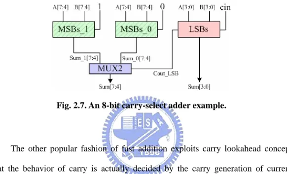
(27) TDM requires the delay information of each cell used in the PPRT and then three-dimensionally constructs a speed optimized PPRT using the cells available. The thought of regulating the PPA in [9] stems from the fact that TDM is also implemented in their work. Irregularity of PPA diminishes the optimization of PPRT in accordance with TDM [9]. Since the TDM takes cell delay information as inputs, the optimized PPRT is cell-dependent and thereby library-dependent. Generally speaking, TDM is a sorting algorithm; we can implement a generator coded in high-level languages to facilitate the generation of the speed optimized PPRT. Later in [20], Oklobdzija et al. prove that TDM is truly optimized, not just improved.. 2.2.3 High-Speed Adders To complete fast multiplication, it must take a fast PPG, a speed optimized PPRT, and also a high-speed adder. In general, fast addition concerns the fast generation of carries or correct prediction of the behavior of carries. In this section, two fast addition schemes – carry-select addition and prefix addition – are introduced with conceptual description. Fig. 2.7 demonstrates an 8-bit example of a carry-select adder (CSKA) or a conditional-sum adder (CoSA): an operand is partitioned into several blocks (bit width can be fixed or variable). Instead of waiting carry-out from the block LSBs, a CSKA or CoSA duplicates blocks of MSBs, and calculates the sum of the two blocks in parallel by presuming the carry-in bit to be one or zero, respectively. Since the carry-in must be either one or zero, the correct answer can be selected from one of the two MSBs blocks. A two-to-one multiplexer (MUX2) can simply use the. 16.
(28) carry-out from the LSBs block as the selection signal to pick the correct answer. This scheme is fast because every block in Fig 2.7 processes in parallel, so for the 8-bit example, the critical path is the addition time of the LSBs block plus a MUX2 selection time. However, since duplicated hardware is used, the area approximately doubles the normal case that uses only one MSBs block.. Fig. 2.7. An 8-bit carry-select adder example.. The other popular fashion of fast addition exploits carry lookahead concept that the behavior of carry is actually decided by the carry generation of current inputs or carry propagation of previous carry generation or carry-in. This makes it possible to anticipate the carry. The anticipatory signals are faster because they pass fewer gates, but it takes many more gates to anticipate the proper carry [21]. This concept can be further generalized to parallel prefix computation which observing that block-level generate/propagate signals can also be grouped using prefix operators [3]. Various parallel prefix addition schemes exist such as Brent-Kung [22] and Han-Carlson [23]. In general, the more the parallel-prefix operators are used, the faster the addition completes; however, the actual speed depends on implementation details. A high performance addition scheme on the grounds of Ling addition [24] is presented in [25]. It reduces one logic level over the original Ling Adder in theory 17.
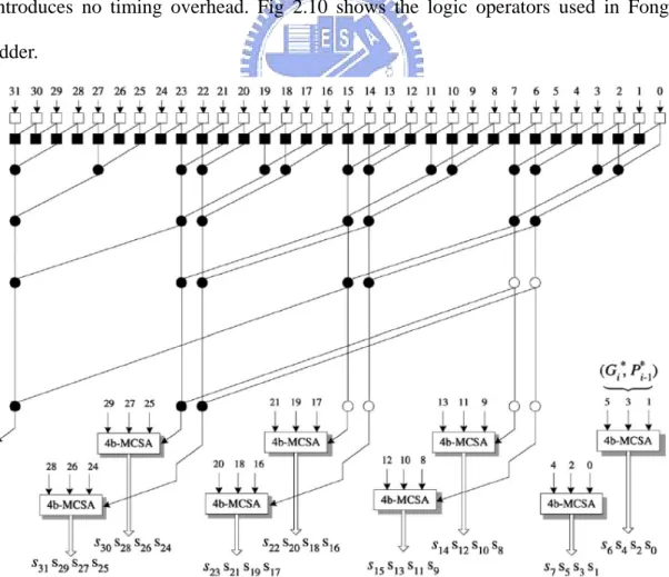
(29) and also minimizes the fan-out of each prefix operator while implemented. In [26] the area is further reduced by fully exploiting the idea of hybrid addition. As a result, considering both in theory or implementation, a high-speed, area-minimized, hybrid Ling adder, which is called “Fong adder” for the remaining context, is presented in [26]. Fig. 2.8 shows a 32-bit architecture of the speed improved hybrid Ling adder [25]: The fan-out of each logic operator is properly taken care of and some modified carry-select adders (MCSAs) are used – the hybrid part – to obtain the result. Fig. 2.9 shows the architecture of a 32-bit Fong adder: Compared to [25], MCSAs with large area are replaced with simple carry select adders (SCSAs) and a ripple-carry adder (RCA), resulting a smaller area cost. This is done by implementing some logic operators working in parallel with prefix operators in each level and hence introduces no timing overhead. Fig 2.10 shows the logic operators used in Fong adder.. Fig. 2.8. Architecture of a 32-bit hybrid parallel-prefix/carry-select Ling adder. *This figure is a direct copy of Fig. 8 in [25] 18.
(30) Fig. 2.9. Architecture of a 32-bit scalar Fong adder. *This figure is a direct copy of Fig. 30 in [26]. Fig. 2.10. Logic operators used in Fong adder.. 19.
(31) 2.2.4 Sub-Word Parallelism (SWP) The utilization of parallel processing leads to a boost in performance. It is a key feature among modern multimedia extensions and DSP processors [6]. A direct implementation of parallel processing is to duplicate hardware such as dual-MAC architecture in ADI-Blackfin® series [27] or quad-MAC architecture in TI-C6000® family [28] DSP processors to increase throughput. However, if given a 16-bit fixed-point (FXP) DSP processor designated for multimedia applications, the original 16-bit datapath is a waste and consumes unwanted power when lower-precision data such as 8-bit pixels are under processing. Duplicating hardware usually damages the hardware utilization rate. Sub-word parallelism (SWP) or sub-word parallel processing serves as a solution to improve hardware utilization rate and increases throughput by exploiting parallel processing concept. Viewed as a form of Single-Instruction-Multiple-Data (SIMD), SWP is a technique to divide an operand (hardware) into multiple lower-precision ones, conditionally uses the whole or part of the hardware, and thereby raises the hardware utilization rate without introducing significant overhead. For example the same 16-bit scalar hardware can simultaneously process two 8-bit data and hence double the throughput. In order for clear and precise explanation, we refer the terms SWP, vectorizing, slicing, segmenting, and partitioning to the same concept as described above, and sub-words (SWs), vectors, slices, segments, and elements are the same product after performing SWP. The term scalar represents a status without utilizing SWP. SWP concept is of great performance help [29], [30], and SWP datapath units are hence developed. If all units are sub-word parallelized, both scalar and SWP operations can be executed and the computing ability will magnificently increase. 20.
(32) compared to a scalar only architecture. For example, [31], [32], [10], and [26], all propose an SWP adder architecture. Concerning our work, the SWP multiplier requires an SWP PPG, an SWP PPRT, and also an SWP CPA. The major difference between the scalar and the SWP architecture lies in the existence of the invisible “boundaries” between SWs. As for multiplication, involving PPs accumulation, the carry-out behavior of each SW should be manipulated. In this section, two SWP PPG methods are explained; SWP accumulation will be discussed and compared with the proposed design together in Chapter 3. A non-Booth encoded multiplier architecture [6], based on Baugh-Wooley algorithm [33], finds that most bits in the signed PPA overlap those in the unsigned PPA. Concerning SWP, it arranges the PPAs of different SWP modes as shown in Fig. 2.11: Observing that most bits in 8-bit SWP PPA P0, P1, P2,and P3 in Fig. 2.11c are identical to those of 16-bit PPA P0 and P1 in Fig. 2.11b, or 32-bit scalar PPA P0 in Fig. 2.11a, it indicates most bits in different SWP modes can share with one another. The only effort is on each SW boundary and on managing fields of zeros (Z8 or Z16). Since the architecture is not modified Booth encoded, it has more PPs and has worse performance in terms of speed; however, a non-MBE architecture usually consumes less power [36]. This MUL/MAC architecture can further functionally integrate the sum-of-square operation into the same PPA without much overhead [34], resulting in a sub-word parallel multiplication and sum-of-square unit (SPMSSU) [35].. 21.
(33) Fig. 2.11. A simplified PPA for 32 × 32 multiplication in different modes. 22.
(34) A 64-bit fixed-point (FXP) vector MAC architecture capable of supporting multiple precisions is presented in [10] and [11]; it can perform one 64 × 64, two 32 × 32, four 16 × 16, or eight 8 × 8 bit signed/unsigned MAC operations using essentially the same hardware of a scalar 64-bit modified Booth encoded MAC. These papers also compare different SWP PPA methods and propose one called shared segmentation. The shared segmentation method exploits substantially the same concept as done in [6] (described in the preceding paragraph). Most bits in a vector mode overlap with those in another mode, producing similar SWP PPA as Fig. 2.11. It also designs an SWP Wallace PPRT using a special FA at SW boundaries and an SWP CPA using 4-bit CLA blocks. Fig. 2.12 depicts a detailed 32-bit PPA example of the shared segmentation method: Fig. 2.12a, Fig. 2.12b, and Fig. 2.12c illustrates the PPA in 32-bit (scalar), 16-bit, and 8-bit vector mode, respectively. Fig. 2.12d displays the PPs overlap among vector modes; it’s clearly shown in the figure that many bits take no effort on selection. It implies there’s no need to use a 32-bit, a 16-bit and an 8-bit MBEs to generate three PPs and use three-to-one multiplexers (MUX3s) for selection; All that’s required is the 32-bit MBE output associated with some multiplexing at 16-bit and 8-bit vector boundaries. It just takes some timing and area overhead to “vectorize” a scalar MAC using shared segmentation method. However, this architecture limits the SW combination and places restrictions on constructing the vector PPRT. The vector CPA in this work can also be improved. As a result, the proposed SWP PPA resembles and improves the shared segmentation PPA described in this section.. 23.
(35) 24.
(36) Fig. 2.12. Shared Segmentation PPA for 32×32 multiplication in different modes.. 25.
(37) 2.3 Summaries of Previous Works The multiplication flow of a scalar MBE multiplier can be partitioned into three steps – PPG, PPRT, and CPA. For PPG, a race-free encoding scheme which outperforms other schemes in terms of timing, area, and power consumption is proposed. Sign encoding that prevents sign extension, and hot-one modification that integrates LSB with hot-ones both make the PPA more regular. PPRT often uses levels of FAs to perform carry-save addition, and TDM is an algorithm that helps construct a speed optimized PPRT. The number of PPs after the PPRT is reduced to two. A CPA is used to sum the two PPs to obtain the final product. SWP increases throughput and provides a performance boost in multimedia extensions or DSP processors. Without much overhead, SWP can be applied to MUL/MAC unit by rearranging PPA and the support of SWP accumulation. The proposed scalar and SWP designs improve and innovate while utilizing some previous works. We’ll describe the proposed designs in more detail in the next chapter.. 26.
(38) CHAPTER 3 PROPOSED MAC DESIGNS 3.0 Overview In this chapter, the design methodology of the proposed MAC designs is elaborated. Section 3.1 presents the scalar version of the proposed MAC design: as described in Chapter 2, the MAC unit consists of three parts – PPG, PPRT, and CPA. Based on the scalar MAC architecture, Section 3.2 enunciates the sub-word parallel (SWP) version of the proposed MAC. The differences, improvements and innovations are compared or highlighted in each section and briefly summarized in Section 3.3.. 3.1 Scalar MAC (SMAC) Design 3.1.0 Specification A high performance scalar MAC design which multiplies the N-bit multiplicand (mcand) by the N-bit multiplier (mlier) with/without accumulating a 2N-bit accumulator (accu) is proposed. It supports signed/unsigned/mixed-mode operation. Table 3.1 lists the specification of the proposed SMAC. Fig. 3.1 shows the proposed SMAC execution flow. To be noted, the carry-out of final result is also provided. Table 3.1. Specification of the proposed SMAC design.. Operation: m_out = accu + mcand × mlier (mode) Bit Width of mcand 8/16/32/64 Bit Width of mlier 8/16/32/64 Bit Width of accu 16/32/64/128 Bit Width of m_out 16/32/64/128 Available modes 01:Signed/00:Unsigned/1?:Mixed-mode 27.
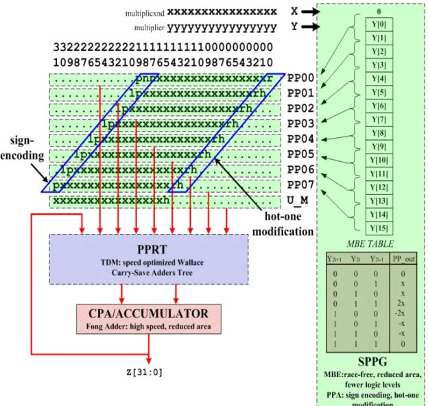
(39) Fig. 3.1. Execution flow of the proposed Scalar MAC design.. 3.1.1 Scalar Partial Product Generation (SPPG) The first phase of SPPG, modified Booth encoding (MBE), is to encode the triplets chosen from the multiplier and then decodes the multiplicand with respect to MBA selection table (Table 2.1). The proposed scalar design favors the race-free concept in [16] that diminishes the energy dissipation, and benefits from the implementation in [9] which saves one logic level and reduces area. A special operating mode, mixed-mode, is integrated into the proposed scalar design. It forces the multiplicand and the accumulator to be signed, the multiplier to be unsigned, and produces a signed result after operation. Mixed-mode operation has a larger dynamic range, and will be explained in detail in Section 5.4. However, the MBE scheme in [9] only applies to signed operands. To support unsigned/mixed-mode operation, some modification must be performed on the MBE. 28.
(40) By specification, both unsigned and mixed mode treat mlier, the multiplier, as an unsigned number; however, due to two’s complement (TC) format natively utilized in MBA, the MSB of mlier is the negatively weighted sign bit. It implies N+1 bits are required in TC format to fully represent an N-bit unsigned number by forcing the (N+1)th bit, the new MSB and sign bit, to a zero. Owing to the existence of the extra zero, an always positive PP is generated to support unsigned/mixed-mode operation. This is why an N-bit DSP processor with an (N+1)-bit MAC unit supporting unsigned multiplication is frequent. Briefly speaking, two methods are used to generate the extra PP. The first method uses MBE to generate by assuming {0,0,m} as the extra encoding triplet where m stands for the MSB of mlier, resulting in a PP equal to zero or mcand since the extra triplet is always {0,0,0} or {0,0,1}. The other method uses a similar concept by observing when unsigned/mixed-mode is asserted, a multiplexer with a string of zeros and mcand as two inputs and m as the control signal can select the extra PP. The result should be identical with the first method. As a result, both methods help unsigned/mixed-mode operation while neither of them influences on signed operation since the MBE selection of the extra signed-extended triplet {m,m,m} or the selection of MUX2s always equals zero. Section 5.1 will detail the way to support unsigned and mixed-mode operation. Using either method, the logic of the extended triplet {s,s,m} or the extended bit s is dependent with m, the MSB of mlier, and the assigned mode under execution. If naming mode[1] as mix (1: mixed-mode; 0: signed/unsigned mode) as well as mode[0] as tc (1: signed-mode; 0: unsigned-mode), the logic of s is derived as:. s = m ⋅ tc ⋅ (~ mix) . (3.1). 29.
(41) In the proposed SPPG, the first method is utilized; besides, signed encoding is also integrated into the MBE, resulting in an N-bit-input and (N+2)-bit-output MBE. Fig 3.2 demonstrates why the output PP requires two-bit extension: assume a 4-bit operand, 1000, is the mcand, and the current encoding triplet is {1,0,0} (-2x); it indicates the negation of mcand followed by one-bit left shift is to be performed. Due to the need of one-bit left shift, a 5-bit temporary data is required, as shown in the second and third rows in the figure. The bit in bit position 5 is used to save the correct sign that may shift out 5-bit data boundary. If the operating mode is different, this saved bit may differ even if LSBs are the same. Moreover, this bit is also useful for sign encoding. Six bits are hence required for correct representation. However, the logic of the extended two bits relates to the operating mode, two 2-input AND gates (AND2) are needed at the most significant two bits of the mcand to generate these two extended bits. These AND2s are added in the decoder in Fig. 2.4 while there’s no logic change on the remaining LSBs. This modification increases a little delay and is still area reduced.. Fig. 3.2. Decoding mcand 1000 in different modes when MBE selects -2x.. 30.
(42) The second phase of SPPG, arranging scalar partial product array (SPPA), is to properly arrange the PPs generated from MBE. Two techniques, sign encoding (SE) and hot-one modification, are used to arrange the proposed SPPA. As mentioned in Section 2.2.1, SE is done by replacing the sign-extension bits with {p,n,n} for the first PP and {1,p} for others, where n stands for the sign bit of the PP and p = ~n. This technique reduces the number of sign-extension bits to two or three and then considerably saves the area and power consumption as bit width grows. Hot-one. modification. aligns. the. hot-one. bits,. obtained. by. two’s. complementing of the preceding PP, all to the left position (hot2) with a slight logic change on the LSB of the preceding PP. It makes the LSB end of the PPA shorter and regular. Both techniques help the proposed SMAC create a narrower-width SPPA which occupies less area, consumes less power, and assists the speed optimization of TDM PPRT. The proposed SPPG is architecturally similar to the PPG in [9].. 3.1.2 Scalar Partial Product Reduction Tree (SPPRT) Three-dimensional method (TDM) [8] is utilized to construct the proposed SPPRT with the architecture of Wallace Tree. A full-adder (FA) is the basic cell to build levels of CSAs. Fig. 3.3 shows the FA cell used in the proposed SPPRT. Concerning TDM, it takes the delay information of each cell used in the tree. Instead of using logic cells like XOR, AND, and OR to build an FA, the SPPRT directly uses the standard high speed FA cell provided by the cell library. This helps not only simplify the generation algorithm but also estimate the delay more accurately. All that is required is to look up in the cell library databook [37] for the delay of six. 31.
(43) paths in an FA (a-to-sum, b-to-sum, cin-to-sum, a-to-cout, b-to-cout, and cin-to-cout). A simple software generator is developed to connect the FAs in the SPPRT using TDM. TDM can be further optimized if the arrival time of each input bit of PPRT is given. It implies that this optimization is cell library dependent and hence and is hard to be reusable. Considering the proposed design, it is easy to obtain reusability. Although the delay information is cell library dependent, to look it up and send it into the software generator to rebuild another SPPRT is effortless since only a standard FA cell is used. However, it’s not suitable to use the whole input signal delay profile to build the SPPRT since the synthesizer may generate different SPPG netlist each time the timing constraint varies. The ever-changing delay profile makes the PPRT not speed optimized and perhaps not reusable. As a remedy, logic optimization is left for the synthesizer to make. Since the delay profile is unpredictable and eventually a kind of estimation, the proposed scalar design simply assumes all signals arrive to the SPPRT simultaneously, leading to a reusable TDM SPPRT.. Fig. 3.3. FA cell used in the proposed SPPRT.. 32.
(44) 3.1.3 Scalar Carry-Propagate Adder (SCPA) Both adders in [8] and [9] exploit the input operand delay profile to configure a hybrid adder scheme to accelerate addition and reduce area. This again is cell library dependent and hence is hardly reusable. For the proposed scalar design, architectural optimization using delay profile is not recommended. Each bit of two operands of the SCPA hypothetically leaves the SPPRT and arrives at the same time. Fong adder [26] is implemented as the SCPA. The architecture of a 32-bit Fong adder has been shown in Fig. 2.9. There are three main reasons that Fong adder is utilized. First, it outperforms most other adders in terms of delay while it minimizes area cost compared to similar architectures. Second, the carry-out bit is provided so as to perform overflow/underflow check. Last but not least, Fong adder also supports SWP that meets our requirement with only a slight delay and area overhead. The proposed SWP scheme is described in Section 3.2.. 3.1.4 Summaries of the Proposed Scalar MAC Design Fig 3.4 displays the proposed scalar architecture. It is partitioned into SPPG, SPPRT, and SCPA. In SPPG, a race-free encoding scheme is utilized with a high-speed and area-reduced MBE implementation supporting signed, unsigned, and mixed-mode operation. Sign encoding and hot-one modification are applied on the proposed SPPA. In SPPRT, a speed optimized reusable PPRT exploiting TDM is built. As for SCPA, Fong adder is used. Note the figure actually shows the multiplier design. It can easily perform MAC operation simply by feeding the multiplication result into SPPRT as another PP. The proposed SWP design utilizes essentially the same hardware of the proposed scalar design. The way to perform SWP is described in the next section.. 33.
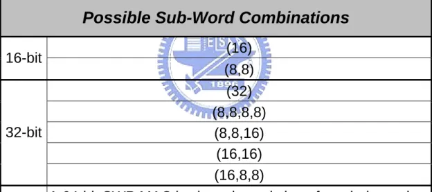
(45) Fig. 3.4. The proposed scalar architecture.. 3.2 Sub-Word Parallel MAC (SWP MAC) Design 3.2.0 Specification A high performance sub-word parallel MAC (SWP MAC) design based on the SMAC architecture is proposed. Table 3.2 lists the specification of the SWP MAC. Kill signals separate SWs and each SW independently processes in its unique mode. Table 3.3 lists the possible sub-word combinations. The detailed SWP reconfiguration scheme is provided in Section 5.3.. 34.
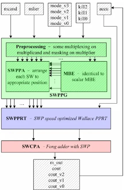
(46) Table 3.2. Specification of the proposed SWP MAC design.. Operation: m_out = accu + mcand × mlier (mode)(kill) Bit Width of mcand Bit Width of mlier Bit Width of accu Bit Width of m_out Bit Width of a Basic SW Bit Width of Each Kill Bit Width of Each Mode Available mode. 8/16/32/64 8/16/32/64 16/32/64/128 16/32/64/128 Input:8/Output:16 1 2 01:Signed/00:Unsigned/1?:Mixed-mode; independence among all sub-words. Table 3.3. Possible sub-word combinations of the proposed SWP MAC design.. Possible Sub-Word Combinations (16) (8,8) (32) (8,8,8,8) 32-bit (8,8,16) (16,16) (16,8,8) A 64-bit SWP MAC is viewed consisting of two independent 64-bit 32-bit SWP MACs; it has 5×5=25 possible combinations 16-bit. 3.2.1 Sub-Word Parallel MAC Execution Flow Fig 3.5 shows the execution flow of the proposed SWP MAC: it is still partitioned into three main parts – SWPPG, SWPPRT, and SWCPA. To apply SWP, some modification should be made in each part – mostly lies in the preprocessing of SWPPG. SWPPG is described in Section 3.2.2; SWP accumulation is divided into. 35.
(47) SWPPRT and SWCPA and explained in Section 3.2.3 and 3.2.4, respectively.. Fig. 3.5. Execution flow of the 32-bit proposed SWP MAC design.. 3.2.2 Sub-Word Parallel PPG (SWPPG) The proposed SWPPG has an identical MBE scheme as used in scalar PPG. The difference lies in the preprocessing on the input operands and the arrangement of the sub-word parallel partial product array (SWPPA). The additional logic for SWP processes mostly in parallel with the SPPG; this enhancement incurs only a. 36.
(48) slight timing overhead and some area overhead. Operand preprocessing consists of two parts – masking and multiplexing on the multiplier and multiplexing on the multiplicand. Fig 3.6 shows a 32-bit example of masking and multiplexing on the multiplier: The bottom SW_0 is the 32-bit multiplier in scalar mode. There is a zero assumed to the right of the LSB for the use of first encoding triplet while there are two s0 bits, for the use of unsigned/mixed-mode operation, extended to the left of MSB where s0 is generated according to Eq. (3.1). These bits are necessary to complete MBE operation. When SWP modes are under execution, the assumed zero and the extend s bits should be appended to each SW as done in scalar mode. For instance in the top row of Fig.3.6, zeros are assumed at mlier[-1], mlier[7], mlier[15], and mlier[23], and s bits are extended to the left of each SW’s MSB. This modification results in 3-bit overlap between SWs, and some bits differ among SWP modes. Therefore mode-dependent multiplexing (selection) or zero-masking are required at these bit positions.. Fig. 3.6. A 32-bit example of masking and multiplexing on the multiplier.. To take an example, the fifth encoding triplet in 32-bit or 16-bit mode is mlier[9:7]; in 8-bit mode, mlier[7] should be masked to a zero, resulting a {mlier[9:8],0} encoding triplet. This demonstrates the necessity of zero-masking. 37.
(49) between SW boundaries. Concerning multiplier multiplexing, it is important to note that the overlapped triplets {s0,s0,mlier[7]} between SW_0 and SW_1 in 8-bit mode for the use of unsigned/mixed-mode correction, is not sent to the MBE; instead, the correction PP is generated, simply using an 8-bit MUX2. This multiplexing eliminates the ambiguity in selecting which triplet to MBE. The MSB of SW_0, mlier[7] in this case, is the selection signal of the MUX2, i.e. when mlier[7] equals 1-bit one, mcand[7:0] as correction PP for SW_0 is required. The same idea can be applied to each SW boundary, avoiding using some 8-bit or 16-bit MBEs to generate correction PPs. All this is required is the scalar 32-bit MBEs. As for preprocessing on multiplicand, the proposed SWPPA arranges PPA of each SW similar to what has been explained in Section 2.2.4. Some bits overlap and remain the same among different SWP modes while some bits, especially bits at SW boundaries, vary and require mode-dependent multiplexing (selection). The difference is in sign encoding (SE) bits plus one bit saved for the sign of PP and the hot-one modification bits. Fig. 3.7 shows the detailed view of the 32-bit proposed SWP PPA: Fig 3.7a shows the SWP PPA in scalar mode in which we can see 17 PPs including accumulator; SE bits and hot-one modification bits are also shown. Fig 3.7b displays the SWP PPA in 16-bit mode: the SE bits and the sign-bit of PP08 shares those of scalar PP08 while the hot-one modification bits don’t share; in contrast, PP01 has a same hot-one modification bits while it differs in SE bits and the sign-bit. Fig 3.7c depicts the 8-bit SWP PPA. Clearly, it tells that the difference mainly lies at SW boundaries. Fig 3.7d exemplifies the selection of PP01 among different modes. Although there exists three modes, only three bit positions actually require a 3-to-1 multiplexer (MUX3) for selection; some take AND2s or MUX2s while some do not demand any selection. As a note, even in the 64-bit proposed SWP design, the proposed SWP PPA requires still MUX3s for worst-case positions. 38.
(50) 39.
(51) Fig. 3.7. Detailed view of the 32-bit proposed SWPPA with a selection example. 40.
(52) Therefore the preprocessing on multiplicand concerns the generation of SE bits, sign bits of PPs, and hot-one modification bits of each SW and their selection among modes. Table 3.4 lists the truth table of SE bits and sign bits of PPs used in the proposed SWP design. Table 2.5 and Eq. (2.1) have shown the logic of hot-one modification bits. These bits are generated in parallel with scalar MBE without introducing any timing overhead since their logic is not as complicated as an MBE. The area overhead, as demonstrated in Fig. 3.7d, is not huge since most bits share those in the scalar PPA.. Table 3.4. Truth table of sign encoding bits and sign bits of PPs.. tc. Y2i+1. Y2i. Y2i-1. 0. 0. 0. 0. 0. 0. n. s. m=0. m=1. m=0. m=1. 0. 0. 0. 0. 0. 0. 1. 0. 0. 0. 0. 0. 1. 0. 0. 0. 0. 0. 0. 0. 1. 1. 0. 0. 0. 1. 0. 1. 0. 0. 1. 1. 1. 0. 0. 1. 0. 1. 1. 1. 1. 1. 0. 1. 1. 0. 1. 1. 1. 1. 0. 1. 1. 1. 0. 0. 0. 0. 1. 0. 0. 0. 0. 0. 0. 0. 1. 0. 0. 1. 0. 1. 0. 1. 1. 0. 1. 0. 0. 1. 0. 1. 1. 0. 1. 1. 0. 1. 0. 1. 1. 1. 0. 0. 1. 0. 1. 0. 1. 1. 0. 1. 1. 0. 1. 0. 1. 1. 1. 0. 1. 0. 1. 0. 1. 1. 1. 1. 0. 0. 0. 0. tc: 1:signed/0:unsigned; Y: multiplier; m: MSB of SW; s: sign of corresponding PP; n: SE bit. 41.
(53) Thanks to this SWP PPA, the proposed architecture offers more flexible SW combination schemes than previous works if both SWPPRT and SWCPA also support. The SWP combination scheme is controlled by the pre-decoded input kill signals. The pre-decoding is performed in parallel with the scalar MBE and thereby does not incur timing overhead. Fig. 3.8 shows the SWP schemes of the 32-bit proposed SWP design: Each kill signal conditionally enables/disables the carry-chain. Three kill signals provide 8 SW combinations; however, if {kill2,kill1,kill0} equals {0,0,1}, {1,0,0}, or {1,0,1}, the middle 16-bit SW obtains a fault PPA since the corresponding PPA has never been generated in this region. Fig. 3.8a to Fig. 3.8e shows the possible five SW combinations; Fig. 3.8f displays an invalid SW combination scheme. For 64-bit design using the proposed architecture, two 32-bit SW halves process in parallel, offering a total of 25 (5×5) different SW combinations.. Fig. 3.8. SW combinations of the 32-bit proposed SWP MAC design.. 42.
(54) The proposed SWP design is characterized by SWP mode assignment as well; each SW has its own operating mode. To take an example, if a 32-bit SWP operates in 8-bit SWP mode as sketched in Fig. 3.8b, the four SWs don’t have to perform the same signed/unsigned/mixed-mode MAC operation at the same time. Instead, each SW assigns its unique mode signal, and a total of 81 (3×3×3×3) different SW mode assignment schemes are allowed. Moreover a central mode signal assigned to all SWs, as used in [10], introduces high fan-out, and which consequently requires buffer insertion. SWP mode assignment ameliorates high fan-out. Although this modification increases some input ports and places some restrictions on mode assignment, it provides reconfigurability and flexibility for the proposed design. Compared to the 64-bit proposed design, [10] offers only four SW combinations and all SWs should operate in a same central mode, and mixed-mode is not supported.. 3.2.3 Sub-Word Parallel PPRT (SWPPRT) To add SWP in the scalar PPRT, the behavior of carries traversing SW boundaries requires careful manipulation. On the whole, it involves carry-killing (blocking, breaking, disabling, etc) at SW boundaries on each level in the SWPPRT. Both the proposed SWPPRT and the VPPRT in [10] exploit Wallace CSA Tree, using an FA as the basic building block. It implies both designs judiciously manage the carry-out or carry-in of FAs to conditionally break the carry-chain. For example, Fig. 3.9 sketches an image at a SW boundary: Assuming FA_0 is at the MSB of SW_0 and FA_1 is at the LSB of SW_1, there are two ideas to break the carry-chain – ignoring the carry-in of FA_1 or disabling the carry-out of FA_0. It implies new FA cells are required, without glue logic, for the use at SW boundaries.. 43.
(55) Fig. 3.9. Breaking the FA carry-chain for SWP in SWPPRT.. The first idea is utilized in [10]. Considering an FA used at the LSB of SW_1, the signal cin receives the FA carry-out from MSB of the previous SW_0, and hence requires masking on cin using the signal kill. Fig 3.10 shows the FA with carry-in masking used in [10]. This method does not create a new critical path since the paths cin to sum and cin to cout are fast as shown in Fig. 2.6a. Combining cin with kill using NAND2 incurs no significant delay since the extra gate is in parallel with others. This claim is somehow misleading because it implicitly assumes the delays of all signals are balanced and thereby an FA is always assumed to have its longest path latency all the time. This is often not the case with the real circuit since uneven delay among paths do exist, facilitating the speed optimization using TDM [8]. If using the FA scheme at SW boundaries, in Fig. 3.9 cout of FA_0 “must” connect to cin of FA_1 and sum of FA_0 “must” connect to a or b of FA_1. This restricted scheme creates a longer critical path going through all sum signals and all a/b signals since it eliminates the use of TDM to optimize the delay. Furthermore, on the middle levels of Wallace CSA Tree, a lack in cin signals for connection of cout signals is possible and other FA cells may be required.. 44.
(56) Fig. 3.10. FA with carry-in masking used in [10].. The proposed design utilizes a different idea. Since uneven path latency does exist in the proposed SPPRT, TDM can still be utilized. Generally speaking, the more a flexible signal connection is available, the more the speed of a PPRT is optimized. The proposed SWPPRT concerns conditionally disabling the carry-out as shown in Fig. 3.9. A possible realization of FA with carry-out masking used at the MSB of SW_0 is shown in Fig. 3.11.. Fig. 3.11. FA with carry-out masking used in the proposed design. 45.
(57) Whenever kill is asserted, cout must be zero. This modification does not add extra delay to the original FA critical path; however it creates some longer paths compared to the scalar PPRT. It thereby slightly reduces the SPPRT performance since the original FA cells at each MSB of SWs should be replaced by new cells. This method allows flexible FA connection; TDM is thus still feasible. The proposed SWPPRT outperforms the VPPRT in [10] in theory since TDM speed optimization can still be applied. The SWPPRT has nearly the same performance as the SPPRT. Delay information of the new FA cell is required for TDM; for simplicity, we assume the new FA cell has identical delay information with the original FA cell. To configure the SW combination scheme, SWPPRT requires identical kill signals fed into SWPPA. If properly assigned and connected at SW boundaries, the SWPPRT supports equivalent SW combinations as configured in SWPPA.. 3.2.4 Sub-Word Parallel CPA (SWCPA) There are various SWP adder schemes. The basic idea again is to break the carry-chain across SW boundaries. An easy approach to breaking the carry-chain is to conditionally insert one-bit zero between SWs to both operands. This annihilates the carry-chain. When a carry is required, a 1-bit one is simply inserted between SWs to either operand, serving as propagate signal without affecting the result. This approach is less relevant to the adder architecture; however, the delay overhead is considerable as bit width grows. If taking consecutive 16 bits as a basic adder block size, a 32-bit SWP adder requires one inserted bit; a 64-bit adder, three; a 128-bit adder, seven. This enlarges the bit width of the CPA to a number unequal to the power of two, and which deteriorates the performance of CPA since in most architectures the block size usually equals the power of two. Fig 3.12 sketches a simple 64-bit SWP adder scheme. The kill signal controls the annihilate or propagate behavior of the carry. 46.
(58) Fig. 3.12. A simple 64-bit SWP adder.. AN SWP adder using 4-bit carry-lookahead generator (CLG) is implemented in [10]. Similar to the SWP method in VPPRT, an AND2 is added to mask the carry-in of the CLG without additional delay. This CLA logic is expressed as:. cout 0 = g 0 + p 0 ⋅ cin ⋅ (~ kill ) cout1 = g1 + g 0 ⋅ p1 + p 0 ⋅ p1 ⋅ cin ⋅ (~ kill ) cout 2 = g 2 + g1 ⋅ p 2 + g 0 ⋅ p1 ⋅ p 2 + p 0 ⋅ p1 ⋅ p 2 ⋅ cin ⋅ (~ kill ) g[3 : 0] = g 3 + g 2 ⋅ p3 + g1⋅ p 2 ⋅ p3 + g 0 ⋅ p[3 : 0] = p 0 ⋅ p1 ⋅ p 2 ⋅ p3, (3.2) where g[3:0] and p[3:0] stand for 4-bit CLG generate and propagate signal from bit 0 to bit 3, respectively. This adder enjoys the merits of a scalar CLA without large overhead. As for Fong adder exploited in the proposed SCPA, it also enhances for SWP with minor area and timing overhead because extra operators for breaking the carry-chain are added only at boundary bit positions and work in parallel with the original operators as shown in Fig. 3.13. Fong adder is capable of supporting flexible SW combinations with a basic block size. Concerning the proposed SWP MAC design, we choose a size of 16 bits for lowest granularity. The break signals in Fong adder control the behavior of carries across SW boundaries, and thus configure the SWP scheme. The logic of break signals are identical to kill signals used in the proposed. 47.
數據
+7
相關文件
Fermat’s “little” theorem (p. 487) suggests the following primality test for any given number N:.. 1: Pick a number a randomly from {
– Zero flag – destination equals zero – Sign flag – destination is negative – Carry flag – unsigned value out of range – Overflow flag – signed value out of range. • The
A floating point number in double precision IEEE standard format uses two words (64 bits) to store the number as shown in the following figure.. 1 sign
A floating point number in double precision IEEE standard format uses two words (64 bits) to store the number as shown in the following figure.. 1 sign
Understanding and inferring information, ideas, feelings and opinions in a range of texts with some degree of complexity, using and integrating a small range of reading
Understanding and inferring information, ideas, feelings and opinions in a range of texts with some degree of complexity, using and integrating a small range of reading
• To introduce the use of the LPF as a tool for planning the school English Language curriculum; and
Understanding and inferring information, ideas, feelings and opinions in a range of texts with some degree of complexity, using and integrating a small range of reading
• • Linear Mode : Provide Wild Mass Range Linear Mode : Provide Wild Mass Range – – Protein MW determination Protein MW
