高性能離子感應電晶體之可靠度研究及應用
107
0
0
全文
(2) 高性能離子感應電晶體之可靠度研究及應用 Reliability Investigation and Application of High Performance Ion-Sensitive Field Effect Transistors. 研 究 生:趙 高 毅. Student:Kuo-Yi Chao. 指導教授:張 國 明博士. Advisor:Dr. Kow-Ming Chang. 國 立 交 通 大 學 電子工程學系 電子研究所 博 士 論 文. A Dissertation Submitted to Institute of Electronics College of Electrical Engineering and Computer Science National Chiao Tung University in partial Fulfillment of Requirements for the Degree of Doctor of Philosophy in Electronics Engineering. September 2007 Hsinchu, Taiwan, Republic of China. 中華民國九十六年九月.
(3) 高性能離子感應電晶體之可靠度研究及應用. 研究生:趙高毅. 指導教授: 張國明 博士. 國立交通大學 電子工程學系暨電子研究所 博士論文. 摘要 本論文提出使用二氧化鋯(ZrO2)作為離子感應場效電晶體(ISFET)之感 應層,並嘗試去調控溫度與製程參數對ISFET的影響,當我們可以得到一個穩定 的感測靈敏度則因為漂移效應所造成的水合深度就可獲得,當我們瞭解漂移效應 後,我們提出兩種方法來解決此種負面效應。 在第二章中先描述離子感應場效電晶體(ISFET)的理論跟模型,例如,表 面鍵結分離模型、Gouy-Chapman 理論、Gouy-Chapman-Stern 理論、與漂移理論。 在第三章的研究裡,氧化鋯成功的應用在離子感應場效電晶體(ISFET)裡, 成為酸鹼感測層,再利用 HP4156A 以定電流量測方式後,可得到相當高的反應 範圍,其感測靈敏度介於 56.7~58.3 mV/pH 之間。這裡所使用的氧化鋯薄膜是 使用直流濺鍍方式所沈積的,此薄膜對氧化層跟矽晶都具有相當好的吸附特性, 當感測環境加入 1 莫耳體積濃度的氯化鈉容液以後,感應靈敏度會有些微的減 少,不過還是具有相當好的線性度及 52.5 mV/pH 的靈敏度。 在論文的第四章中,我們利用參考場效電晶體(REFET)來控制溫度跟製程 差異的影響,當我們利用參考場效電晶體(REFET)校正輸出訊號後,就可以得 i.
(4) 到一個相當穩定的的感應靈敏度並可以得到以二氧化矽為感測層的離子感應場 效電晶體(ISFET)的初始本質漂移(intrinsic drift),更進而定義出因為漂移影 響所造成的水合層厚度。從實驗的結果來看,用二氧化矽感測層所做成的離子感 應場效電晶體(ISFET)水合深度大約為 50 奈米,而實驗當中所測出來的感測 反應也很穩定,大約處於 28~32 mV/pH 之間,使用這方法可以很簡單的找出水 合深度,這將對探討漂移效應的真正機制有所助益。 當我們暸解漂移現象以後,我們就試著設計兩種方法來減少這個效應,其中 一種方法是在第五章,在這章節當中,我們提出漂移跟閘極電壓的關係,從而設 計出一種簡單且便宜的方法來解決漂移問題。我們利用參考電極來施加不同的定 電壓在感測層上面,就可以很明顯的看出閘極的飄移電壓跟應力電壓的強烈相關 性,當閘極電壓控制在 0.5 伏特,就可以使得以二氧化矽為感測層的離子感應場 效電晶體之飄移電壓從原來的十小時飄移 56.12 mV 變為 2.94 mV,其改善百分 率高達 94.8%。又當閘極電壓被控制在-1 伏特的時候,就可以使得以二氧化鋯為 感測層的離子感應場效電晶體(ISFET)之飄移電壓從原來的十小時飄移-57.94 mV 變為 0.76 mV,其改善百分率高達 98.7%。 另一個解決方法提出於本論文的第六章中,其方法為利用參考感應場效電晶 體(REFET)來減少飄移效應,首先是利用銨電漿去處理一個以二氧化鋯為感應 薄膜的離子感應場效電晶體(ISFET),以得到一個簡單且跟互補金屬氧化電晶 體相容的參考感測場效電晶體(REFET)來量測酸鹼性。這是一個獨創且具有很 高的可塑性,可以整合離子感應場效電晶體(ISFET)到化學微系統,應用於生 物體分析或整合到單晶片系統當中。當我們利用 4156A 以定電流量測方式時, 可以同時得到離子感應場效電晶體(ISFET)、參考感應場效電晶體(REFET) 及兩者間的差值感應靈敏度。這個以二氧化鋯為感測層的離子感應場效電晶體 (ISFET)具有很高的離子感測能力,其範圍介於 56.7~58.3 mV/pH 間,其變異 度為 3%,又參考感應場效電晶體(REFET)具有較小的離子感測能力,其範圍 介於 27.6~29 mV/pH 間,其變異度為 5%。當我們使用離子感應場效電晶體/參 ii.
(5) 考感應場效電晶體(ISFET/REFET)差值電壓對的時候,可以得到一個非常穩定的 差值感應靈敏度,其範圍介於 29.1~29.3 mV/pH 間,其變異度為 0.7%。這個結 果告訴我們,這個研究不僅使得離子感應場效電晶體(ISFET)可以整合到微系 統當中,也可以增加感應靈敏度的穩定性。. iii.
(6) Reliability Investigation and Application of High Performance Ion-Sensitive Field Effect Transistors. Student: Kuo-Yi Chao. Advisor: Dr. Kow-Ming Chang. Department of electronics Engineering & Institute of Electronics National Chiao Tung University. Abstract This dissertation proposes to use zirconium oxide as a membrane of ion-sensitive field effective transistor (ISFET), and to control the effects of temperature and process deviation. When a stable sensitivity and intrinsic drift of SiO2 gate ISFET can be found, the thickness of hydration layer that is introduced by the drift effect will be found, too. After we understand the drift effect, we also propose two methods to solve the unwanted effect. In Chapter 2, theories and models of ISFET are described, including site-dissociation model, Gouy-Chapman theory, Gouy-Chapman-Stern theory, and drift model. Chapter 3 describes the application of the zirconium oxide (ZrO2) membrane as a pH-sensitive layer for ISFETs. It exhibited an excellent response range of 56.7~58.3 mV/pH from the fixed current measurement using HP4156A. The ZrO2 membrane. iv.
(7) prepared by direct current (DC) sputtering was used as a pH-sensitive film that showed good surface adsorption with oxide and silicon. The pH sensitivities slightly decreased in 1 M NaCl solution; however, the device showed a perfect linear response of 52.5 mV/pH. In Chapter 4, a reference field effective transistor (REFET) is used to control the effects of temperature and process deviation. After the calibration of REFET, a very stable sensitivity and intrinsic drift of SiO2 gate ISFET can be obtained. It can be used to define the thickness of hydration layer that is introduced by the drift effect. Results of this study will show that the thickness of hydration is about 50 nm in SiO2 membrane ISFET. It exhibits a stable response of 28~32 mV/pH from the fixed current measurement by HP4156A. This method is a really simple way to find the thickness of hydration layer, and it will be useful in the study of the real mechanism in drift effect. When we understand the phenomenon of drift, we try to design two methods to reduce this effect. One is in Chapter 5. A simple and cheap way to solve the drift problem is presented which describes the relation of drift and gate voltage. Constant various gate voltages are biased in sensing layers with reference electrode. It obviously shows a strong relation of gate drifts and gate stress voltages. When the gate voltage is controlled as 0.5 V, the drift voltage of SiO2 gate ISFET will decrease from 56.12 to 2.94 mV in ten hours measurement. The improvement of drift voltage reaches 94.8%. When the gate voltage is controlled as -1 V, the drift voltage of ZrO2 gate ISFET will also decrease from -57.94 to 0.76 mV. The improvement of drift voltage reaches 98.7%. Another one in Chapter 6 of the thesis is using REFET to reduce the drift effect. A simple CMOS compatible REFET for pH detection by post NH3 plasma surface treatment of a ZrO2 membrane ISFET has been developed. It is a novel study that has v.
(8) latent capacity to integrate the ISFET devices into a chemical micro system for in vivo analysis or become a part of lab-on-a-chip. With the fixed current measurement by HP4156, we can get not only the individual sensitivities of ISFET and REFET, but also the differential sensitivities of ISFET/REFET pair. The ZrO2 membrane ISFET exhibits an excellent response of 56.7~58.3mV/pH with deviation of 3% and the REFET shows a small response of 27.6~29 mV/pH with a deviation of 5%. Using this ISFET/REFET differential pair, we can get a very stable differential sensitivities of 29.1~29.3 mV/pH with a small deviation of 0.7%. This result indicates that the research not only makes the ISFET integrate into a micro system in a simple way possible, but also increases the stability of sensitivity.. vi.
(9) Acknowledgement 一轉眼,幾年的時間就過了,期間交錯著無數的酸甜苦辣,不過一路走來總 算是水到渠成,也算是不負所望,對於多年來,從碩士到博士一路悉心照料的指 導教授張國明博士,心中充滿無數的感激。由於老師自由的寬宏指導方式,因而 增加了學生的思考力與創造力,也由於老師的淵博學識,因而提供了學生無數的 建議與幫助,更難能可貴是,老師總是諄諄教誨學生待人處事的態度,也培養學 生積極樂觀的態度,讓學生受益良多。另外,桂正楣教授在這段時間內亦提供學 生大量的協助與關心,在此,學生由衷的感謝兩位教授多年來的包容照顧。 在研究的日子裡,總需要各式各樣的協助與幫忙,特別感謝實驗室的學長楊 知一、鄧一中、鄭兆禎、鍾元鴻、楊文誌、王敬業、游凱翔、陳在泩,同學朱俊 宜、林俊銘,學弟郭俊銘、林昆鋒、張知天、吳鼎文、傅傳旭、吳冠增、黃俊皓、 許信佑、周庭韋、黃明欽、林佳鴻、陳敬昱、鄧至剛、室友王律堯及不勝枚舉的 實驗室成員,因為有你們的貢獻與協助,使得此研究可以順利進行,也因為你們 的存在,為我的研究生崖添加大量的色彩。另外,對於 NDL、奈米中心、及系 辦的職員亦多所感謝,謝謝你們多年來的熱心服務。 最後當然要感謝最重要的人,就是生我、養我、育我、教我的父母及兄姐, 沒有你們過去的培育、付出,就不會有今天的我,對於女友一路的陪伴及鼓勵亦 是我往前走的原動力,僅以此文致謝所有我身邊的人。. vii.
(10) Contents Abstract (Chinese). i. Abstract (English). iv. Acknowledgement. vii. Contents. viii. Table Captions. xii. Figure Captions. xiii. Chapter 1 Introduction 1.1 ISFETs…………………………………………………………………..…...1 1.2 ChemFETs and ENFETS……………………………..……………......…….2 1.3 REFETs………………………………………………………………..……..3 1.4 Applications…………………………………………………………..……...4 1.5 Outline of the Thesis………………………………………………..………..4 1.6 References………………………………………………………………..…..7. Chapter 2 Theory and Principle 2.1 ISFET’s Model…………………………….…………………………….….14 2.2 The Site-Dissociation Model………………………………………………..16 2.3 The Gouy-Chapman Theory…………………………...……………………19 2.4 The Gouy-Chapman-Stern Theory……………………………...…………..20 2.5 Site-Dissociation and Gouy-Chapman-Stern Model……………………..…20 2.6 Physical Model for Drift…………………………………………………....21 2.7 References…………………………….…………………………...………..25. viii.
(11) Chapter 3 Characteristics of Zirconium Oxide (ZrO2) Gate Ion-Sensitive Field-Effect Transistors 3.1 Backgrounds and Motivation………………………………………...……..32 3.2 Experimental Procedure……………………………………………..….…..33 3.2.1 Device Fabrication………………...…………………………....…….33 3.2.2 Packaging and Measurement………………………………..…...……34 3.3 Results and Discussion……………………………………………..……….34 3.3.1 ID-VDS Characteristics of ZrO2 Gate ISFETs……………..…..……….34 3.3.2 pH Sensitivity of ZrO2 Gate ISFET……………..……………………35 3.3.3 Ratio of Width to Length in Channel Affecting ZrO2 Gate ISFET…...35 3.3.4 Drift of ZrO2 Gate ISFET……………………………...…………..…35 3.3.5 pH Sensitivity of ZrO2 Membrane ISFET in 1 M NaCl Solution…….36 3.4 Conclusions………………………………………………...…………….…36 3.5 References ……………………………………………………………….…37. Chapter 4 Drift Characteristics with Sensing Oxide Thickness Modulation by Co-fabricating ISFET and REFET 4.1 Backgrounds and Motivation…………………………………….................49 4.2 Experimental Procedure……...……………………………………….…….50 4.2.1 Device Fabrication……………….……………………….……….….50 4.2.2 Packaging and Measurement………………………..…………….…..51 4.3 Results and Discussion……………………………………………….….….51 4.3.1 pH Sensitivity of the ISFET/REFET………...………………………..51 ix.
(12) 4.3.2 Drift of the SiO2 Gate ISFET……...……………………….…………52 4.4 Conclusion……………………………………….……………………….…52 4.5 References…………………………………………………………….…….54. Chapter 5 Ultra-Low Drift Voltage by Using Gate Voltage Control in Oxide-Based Gate ISFET 5.1 Backgrounds and Motivation……………………………………….………62 5.2 Experimental Procedure…………………………………………………….63 5.2.1 Device Fabrication………………………..…………………………..64 5.2.2 Packaging and Measurement……………….……………..…….…….64 5.3 Results and Discussion………………………………………………….…..65 5.3.1 ID-VDS Characteristics of the ISFET Devices…………..……………..65 5.3.2 pH Sensitivities of the ISFETs………….…………………………….65 5.3.3 Drift of ISFET………………………………………………..……….66 5.4 Conclusion……………………………………………….…………...……..67 5.5 References…………………………………………………………………..68. Chapter 6 A Simple CMOS Compatible REFET for pH Detection by Post NH3 Plasma Surface Treatment of ISFET 6.1 Backgrounds and Motivation…………………………………………...…..77 6.2 Experimental Procedure………………………………………………..…...78 6.2.1 Device Fabrication……………………..………………………….….78 6.2.2 Packaging and Measurement…………………...……………….……78 6.3 Results and Discussion………………………………………………….….79 6.3.1 The pH Sensitivity of the ZrO2 Gate ISFET………………………….80. x.
(13) 6.3.2 The pH Sensitivity of the ZrO2 Gate REFET……………...…………80 6.4 Conclusion………………………………………………………….……....81 6.5 References……………………………………………………………..…....82 Chapter 7 Conclusions and Future Prospects 7.1 Conclusions………………………………………….….…………..………88 7.2 Future Prospects……………………………………………….………..…..89. xi.
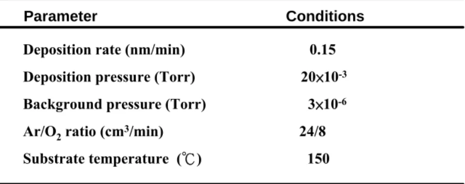
(14) Table Captions. Chapter 2 Table 2-I Sensitivities and test range for the different sensing membranes………...…27. Chapter 3 Table 3-I Growth conditions for film deposition using sputtering system…………...39. xii.
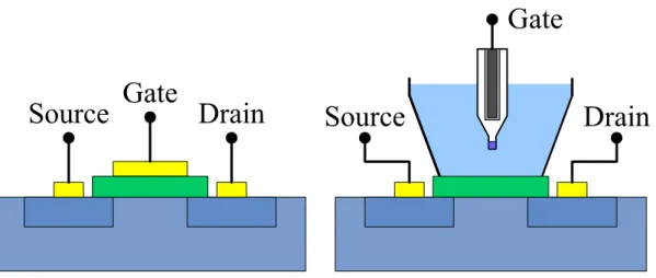
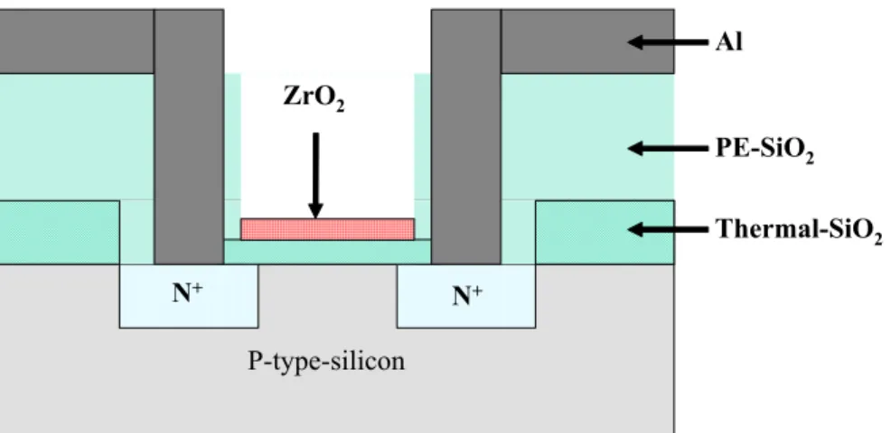
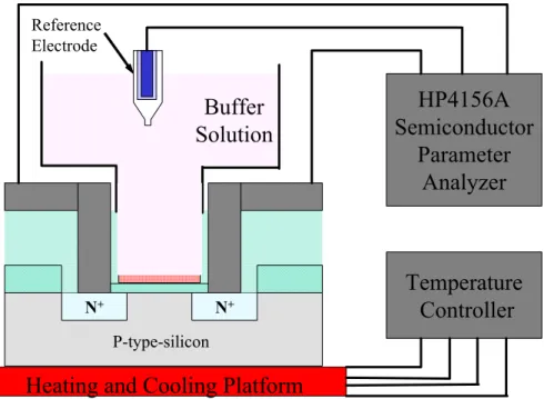
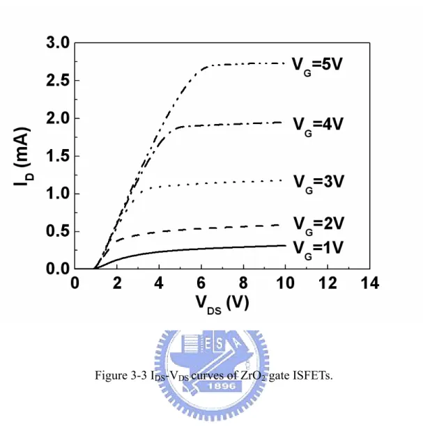
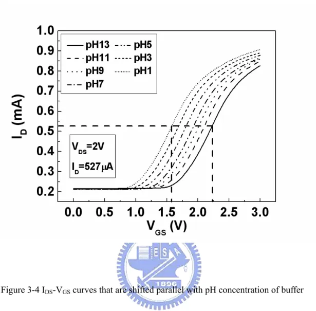
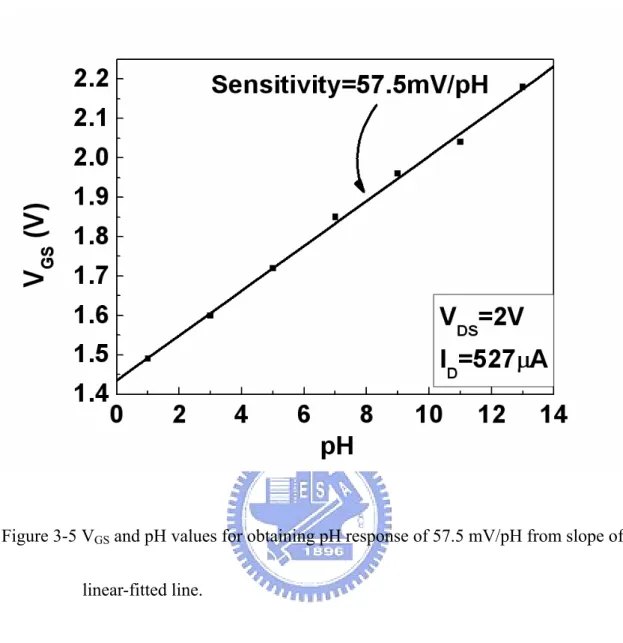
(15) Figure Captions Chapter 2 Figure 2-1 The similarities and differences between MOSFET and ISFET devices. It can be seen that the reference electrode, the aqueous solution and the phenomena occurring at the oxide-solution interface must be accounted for instead of ΦM/q…………………………………………………………...28 Figure 2-2 Potential profile and charge distribution at an oxide electrolyte solution interface (After Siu et al., Ref. 2)………………………………………...29 Figure 2-3 Schematic representation of site-dissociation model……………………..30 Figure 2-4 Series combination of the (a) initial (b) hydrated insulator capacitance…31. Chapter 3 Figure 3-1 Schematic diagram of ZrO2 gate ISFET fabricated by MOSFET technique……………………………………………………………….40 Figure 3-2 Setup of measurement using HP4156A semiconductor parameter analyzer and temperature controller…………………………….………………….41 Figure 3-3 IDS-VDS curves of ZrO2 gate ISFETs……………………………………...42 Figure 3-4 IDS-VGS curves that are shifted parallel with pH concentration of buffer solutions, and in nonsaturation region with VDS = 2 V…………………..43 Figure 3-5 VGS and pH values for obtaining pH response of 57.5 mV/pH from slope of linear-fitted line…………………………………………………………..44 Figure 3-6 Sensitivities of three devices having different ratios of width to length…45 Figure 3-7 Drift of 5.82 mV during 7 h measurement in which a drift of 0.831 mV/h is obtained…………………………………………………………………..46 Figure 3-8 Long-term drift of about 85 mV during 200 h measurement in which a drift. xiii.
(16) of 0.425 mV/h is obtained………………………………………………..47 Figure 3-9 VGS and pH values in 1M NaCl solution for obtaining pH response of 52.5 mV/pH from slope of linear-fitted line………………………………...…48. Chapter 4 Figure 4-1 The schematic diagram of the SiO2 gate ISFET which is fabricated by the MOSFET technique………………………………………………………56 Figure 4-2 The set up of measurement with the HP4156A semiconductor parameter analyzer and temperature controller………………………………...……57 Figure 4-3 (a) The IDS-VGS curves of SiO2 gate ISFET devices (50 nm)………….....58 (b) The IDS-VGS curves of Ta2O5 gate ISFET devices (30 nm)…………...58 Figure 4-4 The VGS to pH values that can obtain the pH response by the slope of the linear fitted line. (a)33.15 mV/pH of SiO2 gate ISFET devices (50 nm). (b) 55.66 mV/pH of Ta2O5 gate ISFET devices (30 nm)…………………….59 Figure 4-5 Drifts in ISFET and REFET during 7 hours……………………………...60 Figure 4-6 Delta drifts of SiO2 gate ISFET devices………………………………….61. Chapter 5 Figure 5-1 Series combinations of (a) initial, (b) hydrated without gate voltage control, and (c) hydrated with gate voltage control……………………………….69 Figure 5-2 Fabricated processes of ISFET which is a CMOS compatible technique..70 Figure 5-3 Setup of measurement Using HP4156A semiconductor parameter analyzer and temperature controller………………………………………………..71 Figure 5-4 (a) ID-VDS curves of SiO2 gate ISFETs…………………………………...72 Figure 5-4 (b) ID-VDS curves of ZrO2 gate ISFETs…………………………………...72 Figure 5-5 (a) ID-VGS curves of SiO2 gate ISFETs…………………………………...73 xiv.
(17) Figure 5-5 (b) ID-VGS curves of ZrO2 gate ISFETs…………………………………...73 Figure 5-6 (a) Sensitivity of SiO2 gate ISFETs………………………………………74 Figure 5-6 (b) Sensitivity of ZrO2 gate ISFETs……………………………………...74 Figure 5-7 (a) Drift of SiO2 gate ISFET with time…………………………………...75 Figure 5-8 (b) Drift of ZrO2 gate ISFET with time…………………………………..75 Figure 5-9 Relation of drift voltages and gate stress voltages……………………….76. Chapter 6 Figure 6-1 The schematic diagram of the ZrO2 gate ISFET that is fabricated by the MOSFET technique………………………………………………………84 Figure 6-2 The set up of measurement with the HP 4156A Semiconductor Parameter Analyzer and Temperature controller…………………………………….85 Figure 6-3 (a) The IDS-VGS curves that are shifted in parallel with the pH concentration of the buffer solutions, and in the non-saturation region with VDS = 2V………………………………………………………………....86 Figure 6-3 (b) The VGS to pH values that can obtain a median pH response of 57.5 mV/pH by the slope of the linear fitted line……………………………...86 Figure 6-4 The sensitivities to post NH3 plasma treatment time output characteristics of the ISFET(W/O Plasma), REFET(W/ Plasma) and ISFET/REFET pair (Differential Sensitivities) devices with VDS= 2V and drain current at 527 μA……………………………………………………………………87. xv.
(18) Chapter 1 Introduction 1.1 ISFETs In the literature relating to ion-selective field-effective Transistors (ISFETs), the 1970’s paper of Bergveld is cited as the first paper [1]. The ISFET is introduced as a new device that combines the chemical-sensitive properties of glass membranes with the characteristics of the metal-oxide-semiconductor field-effect transistors (MOSFET) device. ISFET is a special type of MOSFET without a metal gate, in which the gate is directly exposed to the buffer solution. When there is a change in the surface potential between the gate insulator and the electrolyte, the electric field at the insulator semiconductor interface will be changed and the channel conductance that affects the drain current will also be modulated. Since the channel conductance and drain current can be modulated, we may measure the changes by applying a fixed source to drain voltage or a constant source to drain voltage current and different output gate voltages. By these methods, we can plot a standard linear line between gate voltages and various pH values, and a standard linear line can be taken to measure an unknown acid or an alkaline solution. Compared with the conventional method, ISFET has some advantages such as small size, short-response time, low cost, and complementary metal-oxide-semiconductor (CMOS) compatible processes. The development of ISFET has been on going for more than 35 years, and the first sensitive membrane used is silicon dioxide (SiO2), which showed an unstable sensitivity and a large drift. Subsequently, Al2O3, Ta2O5, SnO2, TiN, a-WO3, indium tin oxide (ITO), and ZrO2 were used as pH-sensitive membranes to achieve a higher pH response and a more stable drift voltage [2~9]. Also some explanations of the mechanisms of operation of the ISFETs [10-16] are appearing. The physical-chemical 1.
(19) models to be used with semiconductor-based devices simulation problems are developed [17-22]. Initially developed for pH detection, ISFETs were also proposed for biomedical, agriculture, environmental, general analytical applications, and food industry [23-34]. However, further improvements and investigations of ISFET performances are needed to promote their use in microsystems for specific applications. Difficulties arise not only from technological issues, but also from the lack of considering first-order mechanisms such as the effects of drift, hysteresis, and temperature. These limiting operating conditions are particularly relevant in respect of possible applications of ISFET-based microsystems in industrial control and monitoring of processes (e.g. biofermenters for biotechnological applications) or where temperature cannot be a controlled parameter. In this study, a simple and cheap way to solve the drift problem is presented which describes the relation of drift and gate voltage. Constant various gate voltages are biased in the sensing layer with reference electrode. It obviously shows a strong relation of gate drift and gate stress voltages. A great improvement of drift voltage can be achieved by using gate voltage controlling method.. 1.2 ChemFETs and ENFETs The classes of chemical sensors that use the FET as an underlying amplification method are called ChemFETs. A variety of ChemFET structures have been proposed and demonstrated. However, the most common class of ChemFETs in both commercial and research uses is the ISFET. The ISFET is characterized by the absence of an explicit gate material; the insulating layer in the FET structure is used as the chemically sensitive layer instead. When the insulator layer is sensitive to enzymes and the gate layer is missing from the FET structure, the resulting ChemFET structure is typically called an enzyme selective FET (ENFET). All ChemFET based 2.
(20) structures work on the basic principle of measuring surface charge changes at the interface between the insulator layer and the overlying layer. Changes in surface charges result in changes in the work function that are in turn, measured as a change in transistor threshold voltage.. 1.3 REFETs A conventional reference electrode (e. g. Ag/AgCl electrode) is always used in the measurement system. If we want to integrate the ISFET devices into a chemical micro system for in vivo analysis or become a part of lab-on-a-chip, the huge conventional reference electrode will be the biggest challenge. For this reason, there are several approaches that have been investigated to solve this problem. One method to solve this problem is co-fabricated an Ag/AgCl electrode with ISFET, including a gel filled cavity and a porous silicon plug [35]. But this solution has a leakage path from reference electrode to solution that will reduce the device lifetime. Another method is applying a differential measurement between an ISFET and an identical FET, which does not react on the ion concentration to be measured, called REFET. This method is deposition on top of the ISFET’s surface one layer, which is an ion-unblocking membrane that is an insulating polymeric layer exhibiting independence on ionic strength. A commonly used material for ion-unblocking layer in REFET is polyvinylchloride (PVC) [36-37]. The REFET with PVC sensitive membrane has a smaller sensitivity of about 20mV/pH, but it will add some processes to fabricate a REFET and is not compatible with integrated circuit (IC) technology. The ZrO2 prepared by dc sputtering process as a pH-sensitive membrane for ISFET is first developed in our laboratory. In this work, we report a simple CMOS compatible REFET by post NH3 plasma surface treatment on ZrO2 gate ISFET. The 3.
(21) electrical characteristics and pH response of the ZrO2 gate ISFET is studied by the standard MOSFET measurement with HP 4156A. Without any unblocking layer to be deposited, the REFET also shows a very low sensitivity of about 28.3 mV/pH. With such ISFET/REFET differential pair, the conventional reference electrode can be replaced by a solid platinum electrode, which can fabricate in the same chip. By this way, a high integration of ISFET with IC fabricating can be realized in the future.. 1.4 Applications There are a wide range of applications for sensors requiring the detection of concentration gradients of metabolites such as oxygen, carbon dioxide, and glucose. Some of the biological applications for sensing the extra cellular gradient of metabolic products include the study of disease, such as diabetes, cancer, and mitochondrial diseases, such as age-dependent infertility in women and Alzheimer’s disease, cell and tissue differentiation, cell and tissue storage, cell life cycle and processes, and developmental biology [38-62].. 1.5 Outline of the Thesis In Chapter 1, the ISFET, REFET, ChemFET, and ENFET are briefly described as new ion sensors which represent the combination of the technologies of a MOSFET. It represents a new approach to obtain the chemical characteristics using electrical devices. In Chapter 2, theories and models of ISFET are described. Such as site-dissociation model, Gouy-Chapman theory, Gouy-Chapman-Stern theory, and drift model are all described here. In Chapter 3, the zirconium oxide (ZrO2) membrane has been successfully applied as a pH-sensitive layer for ion-sensitive field-effect transistors (ISFETs). It 4.
(22) exhibited an excellent response range of 56.7~58.3 mV/pH from the fixed current measurement using HP4156A. The ZrO2 membrane prepared by direct current (DC) sputtering was used as a pH-sensitive film that showed good surface adsorption with oxide and silicon. The pH sensitivities slightly decreased in 1 M NaCl solution; however, the device showed a perfect linear response of 52.5 mV/pH. In Chapter 4, we used a reference field effective transistor (REFET) to control the effects of temperature and process deviation. After the correction of REFET, we can get a very stable sensitivity and intrinsic drift of SiO2 gate ISFET and define the thickness of hydration layer that is introduced by the drift effect. According to the result of this study, the thickness of hydration is about 50 nm in SiO2 membrane ISFET. It exhibits a stable response of 28~32 mV/pH from the fixed current measurement by HP4156A. This method is a really simple way to find the thickness of hydration layer, and it will be useful in the study of the real mechanism in drift effect. In Chapter 5, a simple and cheap way to solve the drift problem is presented which describes the relation of drift and gate voltage. Constant various gate voltages are biased in sensing layers with reference electrode. It obviously shows a strong relation of gate drifts and gate stress voltages. When the gate voltage is controlled as 0.5 V, the drift voltage of SiO2 gate ISFET will decrease from 56.12 to 2.94 mV in ten hours measurement. The improvement of drift voltage reaches 94.8%. When the gate voltage is controlled as -1 V, the drift voltage of ZrO2 gate ISFET will also decrease from -57.94 to 0.76 mV. The improvement of drift voltage reaches 98.7%. This may result from the gate electric field affecting the ions to diffusive into the gate insulator. By this way, we can commercialize the ISFET with a very low drift rate in a simple way. In Chapter 6, a simple CMOS compatible REFET for pH detection by post NH3 5.
(23) plasma surface treatment of a ZrO2 membrane ISFET has been developed. It is a novel study that has latent capacity to integrate the ISFET devices into a chemical micro system for in vivo analysis or become a part of lab-on-a-chip. With the fixed current measurement by HP4156, we can get not only the individual sensitivities of ISFET and REFET, but also the differential sensitivities of ISFET/REFET pair. The ZrO2 membrane ISFET exhibits an excellent response of 56.7~58.3mV/pH with deviation of 3% and the REFET shows a small response of 27.6~29 mV/pH with a deviation of 5%. Using this ISFET/REFET differential pair, we can get a very stable differential sensitivities of 29.1~29.3 mV/pH with a small deviation of 0.7%. This result indicates that the research not only makes the ISFET integrate into a micro system in a simple way possible, but also increases the stability of sensitivity. In chapter 7 of the thesis, some conclusions and recommendations of future works are described.. 6.
(24) 1.6 References [1] P. Bergveld, “Development of an ion sensitive solid-state device for neurophysiological measurements,” IEEE Trans. Biomed. Eng. vol. 17, pp. 70–71, 1970. [2] S. D. Moss, C. C. Johnson, and J. Janata, “Hydrogen calcium and potassium ion sensitive FET transducers,” A preliminary report, IEEE Trans. Biomed. Eng. vol. 25 pp. 49–54, 1978. [3] H. K. Liao, J. C. Chou, W. Y. Chung, T. P., and S. K. Hsiung, “Study on the interface trap density of the Si3N4/SiO2 gate ISFET,”. Proceedings of the Third. East Asian Conference on Chemical Sensors, Seoul, South Korea, pp. 394–400, November 1997. [4] L. T. Yin, J. C. Chou, W. Y. Chung, T. P., and S. K. Hsiung, “Study of indium tin oxide thin film for separative extended gate ISFET,” Mater. Chem. Phys. vol.70 pp. 12-16, 2001. [5] P. Gimmel, B. Gompf, D. Schmeiosser, H. D. Weimhofer, W. Gopel, and M. Klein, “Ta2O5 gates of pH sensitive device comparative spectroscopic and electrical studies,” Sensors and Actuators B vol. 17 pp. 195–202, 1989. [6] J. C. Chou and J. L. Chiang, “Study on the amorphous tungsten trioxide ion-sensitive field effect transistor,” Sensors and Actuators B vol. 66 pp. 106-108, 1998. 7.
(25) [7] T. matsuo and M. Esashi, “Methods of ISFET fabrication” Sens and Actuators vol. 1 pp. 77-96, 1981. [8] J. C. Chou and J. L. Chiang,” Ion sensitive field effect transistor with amorphous tungsten trioxide gate for pH sensing ” Sens and Actuators B vol. 62 pp. 81-87 2000. [9] K. M. Chang, K. Y. Chao, T. W. Chou, and C. T. Chang,”Characteristics of Zirconium Oxide Gate Ion-sensitive Field-Effect Transistors” Japanese Journal of Applied Physics vol. 46 No. 7A pp. 4334-4338, 2007. [10] A. G. Revesz, “On the mechanism of the ion sensitive field effect transistors,” Thin Solid Films vol. 41, pp. 643–647, 1997. [11] P. Bergveld, N. F. de Rooij, and J. N. Zemel, “Physical mechanisms for chemically sensitive semiconductor devices,” Nature vol. 273, pp. 438–443, 1978. [12] W. M. Siu and R. S. C. Cobbold, “Basic properties of the electrolyte-SiO2–Si system: physical and theoretical aspects,” IEEE Trans. Electron Devices ED vol. 26 , pp. 1805–1815, 1979. [13] L. Bousse, N.F. de Rooij and P. Bergveld, “Operation of chemically sensitive field-effect sensor as a function of the insulator–electrolyte interface,” IEEE Trans. Electron Devices ED vol. 30 , pp. 1263–1270, 1983. [14] A. van den Berg, P. Bergveld, D. N. Reinhondt, and E. J. R. Sudholten, “Sensitivity control of ISFETs by chemical surface modification,” Sens. Actuators vol. 8 , pp. 129–148, 1985. [15] C. D. Fung, P. W. Cheung, and W. H. Ko, “A generalized theory of an electrolyte–insulator–semiconductor. field-effect 8. transistor,”. IEEE. Trans..
(26) Electron Devices ED vol. 33, pp. 8–18, 1986. [16] R. E. G. van Hal, J. C. T. Eijkel, and P. Bergveld, “A novel description of ISFET sensitivity with buffer capacity and double-layer capacitance as key parameters,” Sens. Actuators B vol. 24–25, pp. 201–205, 1995. [17] G. Massobrio, M. Grattarola, G. Mattioli, and F. Mattioli, Jr., “ISFET-based bio-sensor modeling with SPICE,” Sens. Actuators B vol. 1, pp. 401–407, 1990. [18] S. Martinoia, G. Massobrio, and M. Grattarola, “An ISFET model for CAD applications,” Sens. Actuators B vol. 8, pp. 261–265, 1992. [19] M. Grattarola, G. Massobrio, and S. Martinoia, “Modeling H+-sensitive FETs with SPICE. IEEE Trans,” Electron Devices, ED vol. 39, pp. 813–819, 1992. [20] G. Massobrio, S. Martinoia, and M. Grattarola, “Use of SPICE for modeling silicon-based chemical sensors,” Sens. Mater. vol. 62 , pp. 101–123, 1994. [21] S. Martinoia and G. Massobrio, “A behavioral macromodel of the ISFET in SPICE,” Sens. Actuators B vol. 62, pp. 182–189, 2000. [22] C. W. Mundt and H. T. Nagle, “Applications of SPICE for modeling miniaturized biomedical sensor systems,” IEEE Trans. Biomed. Eng. BME vol. 47, pp. 149–154, 2000. [23] B. Palan, F. V. Santos, J. M. Karam, B. Courtois, and M. Husak, “New ISFET sensor interface circuit for biomedical applications,” Sens. Actuators B vol. 57, pp. 63–68, 1999. [24] S. Ingebrandt, C. K. Yeung, W. Staab, T. Zetterer, and A. Offenhausser, “Backside contacted field effect transistor array for extracellular signal recording,” Biosens. Bioelectron. vol. 18, pp. 429–435, 2003. [25] M. Albareda-Sirvent, A. Merkoci, and S. Alegret, “Thick-film bio-sensors for pesticides produced by screen-printing of graphite–epoxy composite and biocomposite pastes,” Sens. Actuators B vol. 79, pp. 48–57, 2001. 9.
(27) [26] S. J. Birrell and J. W. Hummel, “Real-time multi ISFET/FIA soil analysis system with automatic sample extraction.” Comput. Electron. Agric. vol. 32, pp. 45–67, 2001. [27] J. Artigas, A. Beltran, C. Jimenez, J. Bartroli, and J. Alonso, “Development of a photopolymerisable membrane for calcium ion sensors. Applications to soil drenage waters.” Anal. Chim. Acta vol. 426, pp. 3–10, 2001. [28] A. Poghossian, A. Baade, H. Emons, and M. J. Schoning, “Application of ISFET for pH measurements in rain droplets,” Sens. Actuators B vol. 76, pp. 634–638, 2001. [29] J. Artigas, C. Jimenez, C. Dominguez, S. Minguez, A. Gonzalo, and J. Alonso, “Development of a multiparametric analyser based on ISFET sensors applied to process control in the wine industry,” Sens. Actuators B vol. 89, pp. 199–204, 2003. [30] P. Bergveld and A. Sibbald, “Analytical and Biomedical Applications of ISFETs,” Elsevier, Amsterdam, Netherlands, 1988. [31] A. J. Cunningham, “Introduction to Bioanalytical Sensors,” Wiley Interscience, 1998. [32] U.E. Spichiger-Keller, “Chemical Sensors and Biosensors for Medical and Biological Applications,” Wiley, New York, 1998. [33] U. Bilitewski and A. Turner (Eds.), “Biosensors in Environmental Monitoring,” Taylor & Francis, London, Philadelphia, 2000. [34] M. Grattarola, G. Massobrio, Bioelectronics Handbook, “Mosfets, Biosensors, and Neurons,” McGraw-Hill, New York, USA, 1998.. [35] R. L. Smith and D. C. Scott, “An integrated sensor for electrochemical. 10.
(28) measurements,” IEEE Trans. Biomed. Eng. BME vol. 33 pp. 83-90, 1986. [36] M. Chudy, W. Wroblewski, and Z. Brzozka, “Towards REFET,” Sensors and Actuators B vol. 57 pp. 47-50, 1999. [37] P. A. Hammond, D.R.S. Cumming, and D. Ali, “A single-Chip pH Sensor Fabricated by a Conventional CMOS Process,” Proceeding of IEEE Sensors vol. 1 pp. 350-355, 2002. [38] M. J. Muehlbauer, E. J. Guilbeau, B. C. Towe, and T. A. Brandon, “Thermoelectric enzyme sensor for measuring blood glucose,” Biosens. Bioelectron., vol. 5, pp. 1–12, 1990. [39] W. J. Whalen, “Some problems with an intracellular pO electrode,” Adv. Exp. Med. Biol., vol. 50, pp. 39–41, 1974. [40] R. T. Kennedy, L.M. Kauri, G. M. Dahlgren, and S.-K. Jung, “Metabolic oscillations in beta-cells,” Diabetes, vol. 51, pp. S152–S161, 2002. [41] S. K. Jung,W. Gorski, G. A. Aspinwall, L. M. Kauri, and R. T. Kennedy, “Oxygen microsensor and its application to single cells and mouse pancreatic islets,” Anal. Chem., vol. 71, pp. 3642–3649, 1999. [42] Q. Zhang, P. Wang, J. Li, and X. Gao, “Diagnosis of diabetes by image detection of breath using gas-sensitive LAPS,” Biosens. Bioelectron., vol. 15, pp. 249–256, 2000. [43] D. L. Keefe, “Aging and infertility in women,” Med. Health, vol. 80, pp. 403–405, 1997. [44] N. R. Sims, “Energy metabolism, oxidative stress and neuronal degeneration in Alzheimer’s disease,” Neurodegeneration, vol. 5, pp. 435–440, 1996. [45] Y.-S. Torisawa, T. Kaya, Y. Takii, D. Oyamatus, M. Nishizawa, and T. Matsue, “Scanning electrochemical microscopy-based drug sensitivity test for a cell 11.
(29) culture integrated in silicon microstructures,” Anal. Chem., vol. 75, pp. 2154–2158, 2003. [46] D. E. Woolley, L. C. Tetlow, D. J. Adlam, D. Gearey, R. D. Eden, T. H. Ward, and T. D. Allen, “Electrochemical monitoring of anticancer compounds on the human ovarian carcinoma cell line A2780 and its adriamycin- and cisplatin-resistant variants,” Exp. Cell Res., vol. 273, pp. 65–72, 2002. [47] B. Liu, S. A. Rotenberg, and M. V. Mirkin, “Scanning electrochemical microscopy of living cells: different redox activities of nonmetastatic and metastatic human breast cells,” in PNAS, vol. 97, pp. 9855–9860, 2000. [48] B. Liu, W. Cheng, S. A. Rotenberg, and M. V. Mirkin, “Scanning electrochemical microscopy of living cells part 2. Imaging redox and acid/basic reactivities,” J. Electroanal. Chem., vol. 500, pp. 590–597, 2001. [49] W. Feng, S. A. Rotenberg, and M. V. Mirkin, “Scanning electrochemical microscopy of living cells. 5. Imaging of fields of normal and metastatic human breast cells,” Anal. Chem., vol. 75, pp. 4148–4154, 2003. [50] C. Cai, B. Liu, and M.V. Mirkin, “Scanning electrochemical microscopy of living cells. 3. Rhodobactersphaeroides,” Anal. Chem., vol. 74, pp. 114–119, 2002. [51] B. D. Bath, E. R. Scott, J. B. Phipps, and H. S. White, “Scanning electrochemical microscopy of iontophoretic transport in hairless mouse skin. Analysis of the relative contributions of diffusion, migration, and electroosmosis to transport in hair follicles,” J. Pharm. Sci., vol. 89, pp. 1537–1549, 2000. [52] E. R. Scott and H. S. White, “Iontophoretic transport through porous membranes using scanning electrochemical microscopy: application to in vitro studies of ion fluxes through skin,” Anal. Chem., vol. 65, pp. 1537–1545, 1993. [53] L. Csonge, D. Bravo, H. Newman-Gage, T. Rigley, E. U. Conrad, A. Bakay, D. M. Strong, and S. Pellet, “Banking of osteochondral allografts, part II. 12.
(30) Preservation of chondrocyte viability during long-term storage,” Cell and Tissue Banking, vol. 3, pp. 161–168, 2002. [54] D. R. Ambruso, D. Mitchell, S. Karakoleva, S. Lavery, J. Otis, T. Danielson, and J. Mladenovic, “Comparison of room temperature (RT) or 4 C storage of cord blood before processing: recovery after freezing,” in 44th Annu. Meeting Amer. Soc. Hematology, Philadelphia, PA, Dec., 6–10 2002. [55] P. D. Ribotta, A. E. Leon, and M. C. Anon, “Effects of yeast freezing in frozen dough,” Cereal Chem., vol. 80, pp. 454–458, 2003. [56] S. L. Holliday and L. R. Beuchat, “Viability of Salmonella, Escherichia coli 0157:H7, and Listeria monocytogenes in yellow fat spreads as affected by storage temperature,” J. Food Protection, vol. 66, pp. 549–558, 2003. [57] N. Mansour, F. Lahnsteiner, and B. Berger, “Metabolism of intratesticular spermatozoa of a tropical teleost fish (Clarias gariepinus),” Comp. Biochem. Physiol. B: Biochem. Mol. Biol., vol. 135B, pp. 285–296, 2003. [58] C. E. Helmstetter, M. Thornton, and N. B. Grover, “Cell-cycle research with synchronous cultures: an evaluation,” Biochimie, vol. 83, pp. 83–89, 2001. [59] S. Umehara, Y. Wakamoto, I. Inoue, and K. Yasuda, “On-chip single-cell microcultivation assay for monitoring environmental effects on isolated cells,” Biochem. Biophys. Res. Comm., vol. 305, pp. 534–540, 1993. [60] P. J. S. Smith and P. G. Haydon, A. Hengstenberg, and S.-K. Jung, “Analysis of cellular boundary layers: application of electrochemical microsensors,” Electrochim. Acta, vol. 47, pp. 283–292, 2001. [61] H. Shiku, T. Shiraishi, H. Ohya, T. Matsue, H. Abe, H. Hoshi, and M. Kobayashi, “Oxygen consumption of single bovine embryos probed by scanning electrochemical microscopy,” Anal. Chem., vol. 73, pp. 3751–3758, 2001.. 13.
(31) Chapter 2 Theory 2.1 ISFET’s Model It is not difficult to find out the similarities between ISFET and MOSFET. The most obvious characteristics are the similarity between their structures. Therefore, the best way to comprehend the ISFET is to understand the operating principle of a MOSFET first. When MOSFET is operated in the so-called linear region, the drain current ID is given by ID =. C OX μW ⎧ 1 ⎫ ⎨(VGS − VT ) − V DS ⎬V DS 2 L ⎩ ⎭. (1). where COX is the gate insulator capacitance per unit area, μ the electron mobility in the channel and W/L the width-to-length ratio of the channel. The threshold voltage VT of Eq. (1) is described by the following expression: VT = VFB −. QB + 2φF COX. (2). where VFB is the flat-band voltage, QB is the depletion charge in the substrate, and ψF B. is the potential difference between the Fermi levels of doped and intrinsic silicon. For a MOSFET with charges presence in the oxide and at the oxide-semiconductor interface, the flat-band voltage can be given by. V FB =. Φ M − Φ Si QOX + Q SS − q C OX. (3). where ΦM is the work function of the gate metal, ΦSi is the work function of silicon, QOX is the charge in the oxide and QSS is the surface state density at the oxide-silicon interface. Substitution of Eq. (3) into Eq. (2), the general form of the threshold voltage of a MOSFET becomes VT =. Φ M − Φ Si QOX + QSS + QB − + 2φF q COX. (4). This equation holds for the MOSFET. But in case of the ISFET, the metal gate is 14.
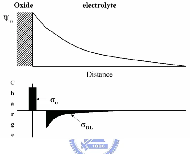
(32) no longer present, so that the term ΦM/q must be revised. Figure 2-1 illustrates the similarities and differences between these two devices. It can be seen that the reference electrode, the aqueous solution and the phenomena occurring at the oxide-solution interface must be accounted for instead of ΦM/q. Bergved and Sibbald [1] showed that the threshold voltage for the ISFET becomes VT = Eref + χ sol − Ψ 0 −. Φ Si QOX + QSS + QB − + 2φF q COX. (5). where Eref represents the constant potential of the reference electrode, χsol is the surface dipole potential of the solution which also has a constant value. The term Ψ0 representing the surface potential at the oxide-electrolyte interface is the key element that makes ISFET pH-sensitive. The surface of any metal oxide always contains hydroxyl groups, in the case of silicon dioxide SiOH groups. These groups can be protonated and deprotonated, and thus, when the gate oxide contacts an aqueous solution, a change of pH will change the SiO2 surface potential. These reactions can be expressed by [2] K1 H S+ + SiOH ←⎯→ SiOH 2+. (6). K2 SiOH ←⎯→ SiO - + H S+. (7). where H S+ represents the protons at the surface of the oxide, K1 and K2 are the dissociation constants of these two chemical equations. The potential between electrolyte solution and insulator surface causes a proton concentration difference between the bulk and surface (Fig. 2-2) that is according to Boltzmann [3] a H + = aH + exp S. B. − qΨ 0 kT. (8). where k is the Boltzmann constant, T is the absolute temperature, a H + and a H + are S. B. the activities of HS+ at the oxide surface and in the solution bulk, respectively. 15.
(33) According to the definition of pH, Eq. (8) can be expressed by pH S = pH B +. qΨ 0 2.3kT. (9). where pHs is the pH value at the oxide surface, pHB is the pH value in the solution B. bulk. The pH response, which is generally called the sensitivity, is defined as the surface potential change over a pH unit change. This response is given by [4] δΨ 0 kT = −2.3 α δpH B q. (10). with. α=. 1 2.3kTCdif q 2 βint. (11). +1. where Cdif is the differential capacitance, and βint is the intrinsic buffer capacity. α is a dimensionless sensitivity parameter. The value of α varies between 0 and 1 depending on the intrinsic buffer capacity and the differential capacitance. If α equals 1, the theoretical maximum sensitivity of -59.2 mV/pH at room temperature can be obtained. Eq. (10) and eq. 11) show that the parameter of α plays an important role of the sensitivity. And the value of α is depend on the relation of Cdif and βint. There are several approaches in colloid chemistry to describe Cdif and βint. Some models will describe as follows.. 2.2 The Site-Dissociation Model There are a lot of inorganic insulators [5-12] which are used for ISFET process technology. The site-dissociation model introduced by Yate et al. [2] is used to drive the intrinsic buffer capacity for these inorganic membranes. This model describes the charges between oxide and electrolyte. The basic assumed is that the surface sites act as discrete sites for chemical reactions at the surface when it is brought in contact 16.
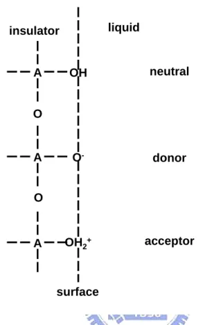
(34) with an electrolyte solution. General speaking, there is only a single type of site to be present with an amphoteric character for the inorganic oxides. That means that each surface site can be neutral, act as a proton donor or act as a proton acceptor. Figure 2-3 shows the surface property of site-dissociation model, where A represents the central atom of oxide molecular. Fundamentally, this can describe the appropriate acidic and basic reactions between the A-OH sites at the surface and the H+ ions in the bulk solution. From the corresponding thermodynamic equilibrium equations, one can calculate the relationship between the interfacial equilibrium potential ψ0 and the H+ ion concentration in the bulk of the solution, [H+]b, or , in other words, the relationship between ψ0 and pH. The most commonly used description, however, is based on the equilibrium between the surface OH groups and the H+ ions located directly near the surface, denoted as HS+. The acidic and basic characters of the neutral site A-OH are characterized by the equilibrium constants Ka and Kb, respectively. The equations can be written as follows: Ka AOH ←⎯→ AO - + H S+. (12). Kb H S+ + AOH ←⎯→ AOH 2+. (13). with:. Ka =. [ AO − ][ H + ]s [ AOH ]. (14). Kb =. [ AOH 2+ ] [ AOH ][ H + ]s. (15). where s means the surface. From above reactions, we can get the following thermodynamic equations: 0 0 μ AOH + kT ln υ AOH = μ AO + kT ln υ AO + μ H0 + kT ln α H −. −. + S. and 17. + S. (16).
(35) 0 0 μ AOH + kT ln υ AOH = μ AOH + kT ln υ AOH + μ H0 + kT ln α H + 2. + 2. + S. (17). + S. where νi is the surface activity and μoi is the standard chemical potential of species i. Equations (3) and (4) can be rewritten as follows:. ν AO aH −. + S. ν AOH ν AOH aH ν AOH. + S. = Ka. K a = exp. with. = Kb. 0 0 μ AOH − μ AO − μ H0. K b = exp. with. −. + b. (18). kT 0 0 μ AOH − μ AOH − μ H0 + 2. + b. kT. + 2. (19). where the K values are dimension less intrinsic dissociation constants. The K values are real constants independent of the ionization state of the oxide surface. When the Boltzmann equation is applied, the surface charge density, σ0, can be given as follows:. σ 0 = q (ν AOH −ν AO ) = qN s (Θ + − Θ − ) + 2. (20). −. where Ns is the density of the available sites; Θ+ and Θ- are the fractions AOH2+ and -. AO of Ns, respectively. The fractions Θ+ and Θ- can be calculated by Eqs (1) and (2), and substituted in (20) to give:. σ 0 = qN s (. aH2 + − K a K b S. K a K b + K b aH + + aH2 + S. ) = − q[ B]. (21). S. Taking the pH variations in the interface of oxide and electrolyte into account, the surface charge density versus the βint pH variation on the surface can be calculated as following definition:. δσ 0 δ [ B] = −q = − qβ int δpH S δpH S. (22). where βint is called the intrinsic buffer capacity, depending on the activity of surface H+-ions . And thus we can finally find the expression for the intrinsic buffer capacity:. β int = N S. K b aH2 + + 4 K a K b aH + + K a K b2 S. S. ( K a K b + K b aH + + aH2 + ) 2 S. 2.3aH + S. S. 18. (23).
(36) 2.3 The Gouy-Chapman Theory According to the charge neutrality, an equal but opposite charge is built up, σDL , in the electrolyte solution side of the double layer. Thus there will be, something like capacitor (Figure 2-2), built up in the oxide/electrolyte system. We can obtain the following Eq. by such equilibrium in Boltzmann equation: ci ( x ) = ci0 exp(. − z i qφ x ) kT. (24). where φx is the potential at any distance x with respect to the bulk of the solution; ci(x) and ci0 are the molar concentrations of species i at a distance x and in the bulk of the solution respectively and zi is the magnitude of the charge on the ions. The combination of the Boltzmann and the Poisson equation, which relates the charge density with the potential, is obtained as follows: 1 2. σ DL = −(8kT εε 0 n 0 ) sinh(. zqψ 0 ) = −C0ψ 0 = −σ 0 2kT. (25). where ε0 is the permittivity of free space and ε is the relative permittivity; n0 is the number concentration of each ion in the bulk. Differentiation of Eq.(25) with respect ψ0 and rearrangement gives the following expression for the differential capacitance: Cdif = (. 2εε 0 z 2 q 2 n 0 12 zqψ 0 ) cosh( ) kT 2kT. (26) The Gouy-Chapman theory has one drawback. The ions are considered as point charges that can approach the surface arbitrarily close. The assumption causes unrealistic high concentrations of ions near the surface at high values of ψ0. an adjustment to solve this problem was first suggested by stern and is described in the next section.. 2.4 The Gouy-Chapman-Stern Theory The Gouy-Chapman-Stern model involves a diffuse layer of charge in the solution 19.
(37) starting at a distance x2 from the surface. The charge in the diffuse layer is [13]: 1 2. σ DL = −(8kT εε 0 n 0 ) sinh(. zqφ2 ) = −C0ψ 0 = −σ 0 2kT. (27). where φ2 is the potential at any distance x2. Differentiating and rearranging (27) gives the following expression for the differential capacitance:. Cdif =. 2εε0 z 2q 2 n0 12 kT 2εε0 z 2q 2 n0 x2 εε 0 kT. ) cosh(zq2kTφ2 ). (. 1 + ( )(. 1. ) 2 cosh(zq2kTφ2 ). (28). To simplify the above equation as follows. x 1 1 = 2 + 2εε z 2 q 2 n 0 1 Cdif εε 0 ( 0kT ) 2 cosh( zq2 kTφ2 ). (29). There will be seen easily, the differential capacitance can be distinguish into two parts, the first term is the contribution of the called diffuse layer, and the second term is the contribution of the Stern layer. Then the following equation will be obtained:. ψ0 =. σ0 Ci ,d. +. σ0 Ci , st. 1. (8kTεε 0 n 0 ) 2 sinh( zq2 kTφ2 ) = φ2 + Ci , st. (30). 2.5 Site-Dissociation and Gouy-Chapman-Stern Model The combination of the site-dissociation model with Gouy-Chapman-Stern model is probably the most widely used combination to describe the oxide/electrolyte solution interface. Dzombak and Morel used the site-dissociation model in combination with the Gury-Chapman model to describe the surface complication of hydrous ferric oxide [14]. The relation between the parameters aH + and ψ0 can be s. derived by solving (21) and (25) to obtain: aH + = s. K b Ciψ 0 + ( K b Ciψ 0 ) 2 − 4 K a K b (q 2 N s 2 − Ci 2ψ 0 2 ) 2(qN s − Ciψ 0 ). 20. (31).
(38) This relation is necessary to link the calculated intrinsic buffer capacity and the differential capacitance.. 2.6 Physical Model for Drift Jamasb firstly proposed the physical model for drift in 1997 [13]. The key point of this model was employing the dispersive transport theory to express the gate voltage drift, which is caused by the hydration effect at the insulator-electrolyte interface. Dispersive transport was briefly reviewed in [15] and it could be characterized by a power-law time decay of the mobility or diffusivity of the form tβ-1, 0<β<1. This time dependence is based on a model that interprets transport in terms of a “random walk”. The origin of random walk is either a) hopping motion through localized states giving rise to hopping transport, or b) multiple trapping from a band of extended states or localized states leading to multiple-trap transport. The multiple-trap transport is generally associated with the motion of electrons or holes in disordered materials. Regardless of the specific dispersive mechanism involved, dispersive transport leads to a characteristic power-law time decay of diffusivity, which can be described by D (t ) = D00 (ω 0 t ) β −1. (32). where D00 is a temperature-dependent diffusion coefficient which obeys an Arrhenius relationship, ω0 is the hopping attempt frequency, and β is the dispersion parameter satisfying 0<β<1. Dispersive transport leads to decay in the density of sites/traps occupied by the species undergoing transport. This decay is described by the stretched-exponential time dependence given by ΔN S / T (t ) = ΔN S / T (0) exp[( −t / τ ) β ]. (33) 21.
(39) where ΔNS/T (t) is the area density (units of cm-2) of sites/traps occupied, τ is the time constant associated with structural relaxation, and β is the dispersion parameter. Since hydration leads to a change of the chemical composition of the sensing oxide surface, it is reasonable to assume that the dielectric constant of the hydrated surface layer differs from that of the sensing oxide bulk. The overall insulator capacitance, which is determined by the series combination of the surface hydration layer and the underlying oxide, will exhibit a slow, temporal change. When drift phenomenon occurs at the surface of an actively biased ISFET, the gate voltage will simultaneously exhibit a change to keep a constant drain current. The change of the gate voltage can be written as ΔVG (t ) = VG (t ) − VG (0). (34). Since the voltage drop inside the semiconductor is kept constant, ΔVG (t) becomes ΔVG (t ) = [VFB (t ) − VFB (0)] + [Vins (t ) − Vins (0)]. (35). where VFB is the flat band voltage and Vins is the voltage drop across the insulator. VFB and Vins are given by VFB = E ref + χ sol − Ψ 0 −. Vins =. Φ Si QOX + QSS − q COX. (36). − (QB + Qinv ) COX. (37). where Qinv is the inversion charge. If the temperature, pH, and the ionic strength of the solution are held constant, Eref, χsol, Ψ0, and ΦSi can be neglected, so the drift can be rewritten as. ⎡ 1 1 ⎤ ΔVG (t ) = −(QOX + QSS + QB + Qinv ) ⎢ − ⎥ ⎣ Ci (t ) C I (0) ⎦. (38). In this study, the gate oxide of the fabricated ISFET was composed of two layers, a 22.
(40) lower layer of thermally-grown SiO2 of thickness, xL, and upper layer of PECVD SiO2 of thickness, xU. CI(0) is the effective insulator capacitance given by the series combination of the thermally-grown SiO2 capacitance, εL/xL, and the PECVD SiO2 capacitance, εU/xU. Ci(t) is analogous to CI(0), but an additional hydrated layer of capacitance, εHL/xHL, at the oxide-electrolyte interface must be took into consideration, and the PECVD SiO2 capacitance is now given by εU/[xU - xHL]. The series combinations of the capacitances are illustrated in Figure 2-4. Therefore, the drift is given by. ⎛ ε − ε HL ⎞ ⎟⎟ x HL (t ) ΔVG (t ) = −(QOX + QSS + QB + Qinv )⎜⎜ U ⎝ ε U ε HL ⎠. (39). From this equation, we observed that drift is directly proportional to the thickness of the hydrated layer. By applying dispersive transport theory, an expression for xHL(t) is given by [16]. {. [. xHL (t ) = xHL (∞) 1 − exp − (t / τ ) β. ]}. (40). with xHL (∞) =. D00ω0β −1ΔN S / T (0) AD β N hydr. (41). where AD represents the cross-sectional area, and Nhydr is the average density of the hydrating species per unit volume of hydration layer. Thus, the overall expression for the gate voltage drift is. ⎛ ε − ε HL ΔVG (t ) = −(QOX + QSS + QB + Qinv )⎜⎜ U ⎝ ε U ε HL. ⎞ ⎟⎟ x HL (∞) 1 − exp − (t / τ ) β ⎠. {. [. ]}. (42). From this equation, we can expect that if the time of gate oxide immersing in the 23.
(41) test-solution is long enough that is in a stable state (determined by the constant τ ), the gate voltage drift will approach a constant value which is greatly dependent on the hydration depth. Δ VG(t) ≒xHL(t)≒xHL(∞). (43). Then we can determinate the hydration depth of the oxide layer.. 24.
(42) 2.7 References [1] P. Bergveld, “Thirty years of ISFETOLOGY What happened in the past 30 years and what may happen in the next 30 years,” Sens. Actuators B vol. 88, pp. 1-20, 2003 [2] D. E. Yates, S. Levine, and T. W. Healy, “Site-binding model of the electrical double layer at the oxide/water interface,” J. Chem. Soc. Faraday Trans. I vol. 70 pp.1807-1844, 1974. [3] W. M. Siu and R. S. C. Cobbold,”Basic Properties of the Electrolyte-SiO2-Si System:Physical and Theoretical Aspects,” IEEE Trans. Electron Devices, ED vol. 26, pp. 1805-1815, 1979. [4] S. Jamasb, S. Collins, and R.L. Smith, A physically-based model for drift in Al2O3-gate pH ISFET’s, Tech. Digest, 9th Int. Conf. Solid-State Sensors and Actuators (Transducers ’97), Chicago, IL, 15-19, pp. 1379-1382, June, 1997.. [5] S. D. Moss, C. C. Johnson, and J. Janata, “Hydrogen calcium and potassium ion sensitive FET transducers,” A preliminary report, IEEE Trans. Biomed. Eng. vol. 25 pp. 49–54, 1978. [6] H. K. Liao, J. C. Chou, W. Y. Chung, T. P., and S. K. Hsiung, “Study on the interface trap density of the Si3N4/SiO2 gate ISFET,”. Proceedings of the Third. East Asian Conference on Chemical Sensors, Seoul, South Korea, pp. 394–400, November 1997. [7] L. T. Yin, J. C. Chou, W. Y. Chung, T. P., and S. K. Hsiung, “Study of indium tin oxide thin film for separative extended gate ISFET,” Mater. Chem. Phys. vol.70 pp. 12-16, 2001. [8] P. Gimmel, B. Gompf, D. Schmeiosser, H. D. Weimhofer, W. Gopel, and M. 25.
(43) Klein, “Ta2O5 gates of pH sensitive device comparative spectroscopic and electrical studies,” Sensors and Actuators B vol. 17 pp. 195–202, 1989. [9] J. C. Chou and J. L. Chiang, “Study on the amorphous tungsten trioxide ion-sensitive field effect transistor,” Sensors and Actuators B vol. 66 pp. 106-108, 1998. [10] T. matsuo and M. Esashi, “Methods of ISFET fabrication” Sens and Actuators vol. 1 pp. 77-96, 1981. [11] J. C. Chou and J. L. Chiang,” Ion sensitive field effect transistor with amorphous tungsten trioxide gate for pH sensing, ” Sens and Actuators B 62 pp. 81-87, 2000. [12] K. M. Chang, K. Y. Chao, T. W. Chou, and C. T. Chang,”Characteristics of Zirconium Oxide Gate Ion-sensitive Field-Effect Transistors” Japanese Journal of Applied Physics Vol. 46 No. 7A pp. 4334-4338, 2007. [13] A. J. Bard and Faulkner, Electrochemical methods fundamentals and applications. Joh n Wiley & Sons, New York, 1980. [14] D. A. dzombak and F. M. M. Morel, “Surface complexation modeling,” Hydrous Ferric Oxide. John Wiley & Sons, New York, 1990. [15] S. Jamasb, S.D. Collins and R.L. Smith, “A physical model for threshold voltage instability in Si3N4-gate H+-sensitive FET’s (pH ISFET’s),” IEEE Trans. Electron Devices vol. 45 1239-1245, 1998. [16] S. Jamasb, “An analytical technique for counteracting drift in Ion-Selective Field Effect Transistors (ISFETs),” IEEE Sens. J. vol. 4, 795-801, 2004.. 26.
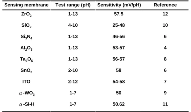
(44) Table 2-Ι. Sensitivities and test range for different sensing membranes. Sensing membrane. Test range (pH). Sensitivity (mV/pH). Reference. ZrO2. 1-13. 57.5. 12. SiO2. 4-10. 25-48. 10. Si3N4. 1-13. 46-56. 6. Al2O3. 1-13. 53-57. 4. Ta2O5. 1-13. 56-57. 8. SnO2. 2-10. 58. 6. ITO. 2-12. 54-58. 7. α-WO3. 1-7. 50. 9. α-Si-H. 1-7. 50.62. 11. 27.
(45) Gate Source. Gate. Drain. Source. Drain. Figure 2-1 The similarities and differences between MOSFET and ISFET devices. It can be seen that the reference electrode, the aqueous solution and the phenomena occurring at the oxide-solution interface must be accounted for instead of ΦM/q.. 28.
(46) Figure 2-2 Potential profile and charge distribution at an oxide electrolyte solution interface (After Siu et al., Ref. 3).. 29.
(47) liquid. insulator. A. OH. neutral. O-. donor. OH2+. acceptor. O. A O. A. surface. Figure 2-3 Schematic representation of site-dissociation model.. 30.
(48) Solution Hydration Sensing Layer Thermal Oxide Silicon (a). (b). Figure 2-4 Series combination of the (a) initial (b) hydrated insulator capacitance.. 31.
(49) Chapter 3 Characteristics of Zirconium Oxide (ZrO2) Gate Ion-Sensitive Field-Effect Transistors 3.1 Backgrounds and Motivation Because many chemical and biological processes are dependent on pH, it is one of the most common parameters measured in laboratories. In the past, a glass electrode was usually used for measuring pH until a brainchild technique based on MOSFET called ISFET was demonstrated by Bergveld in 1970 [1]. ISFET is a special type of MOSFET without a metal gate, in which the gate is directly exposed to the buffer solution. When there is a change in the surface potential between the gate insulator and the electrolyte, the electric field at the insulator semiconductor interface will be changed and the channel conductance that affects the drain current will also be modulated. Since the channel conductance and drain current can be modulated, we may measure the changes by applying a fixed source to drain voltage or a constant source to drain voltage current and different output gate voltages. By these methods, we can plot a standard linear line between gate voltages and various pH values, and a standard linear line can be taken to measure an unknown acid or an alkaline solution. Compared with the conventional method, ISFET has some advantages such as small size, short-response time, low cost, and complementary metal-oxide-semiconductor (CMOS) compatible processes. The development of ISFET has been on going for more than 35 years, and the first sensitive membrane used is silicon dioxide (SiO2), which showed an unstable sensitivity and a large drift. Subsequently, Al2O3, Ta2O5, SnO2, TiN, a-WO3, indium tin oxide (ITO), and ZrO2 were used as pH-sensitive membranes to achieve a higher pH response and a more stable drift voltage [2~9]. Although ZrO2 prepared using an electron beam has been used as a sensing film [9], 32.
(50) there are still many characteristics of the ZrO2 gate ISFET that should be studied, e.g., drift effect or sensitivity in an alkali solution. Table 2-I shows the sensitivities and test ranges of different sensing membranes. We can easily observe that the sensitivity of ZrO2 prepared by direct current (DC) sputtering is the strongest and has a very wide test range. Thus, a ZrO2 thin film is very suitable for applications in ISFETs. In this study, ZrO2 prepared by DC sputtering as a pH-sensitive membrane for ISFET was first developed in our laboratory. The electrical characteristics and pH response of the ZrO2 gate ISFET were studied by standard MOSFET measurement using HP4156A. Drift voltage was also calculated by drain current-to-gate voltage (ID-VG) measurement.. 3.2 Experimental Procedure 3.2.1 Device Fabrication Figure 3-1 shows a schematic diagram of the ZrO2 gate ISFET that is fabricated by the MOSFET technique. A 30-nm-thickness sensitive layer of the ZrO2 membrane was deposited onto the SiO2 gate ISFET by DC sputtering with 4 in. diameter and 99.99% purity of Zr in oxygen atmosphere. The total sputtering pressure was 20 mTorr in the mixed gases Ar and O2 for 200 minutes while the base pressure was 3×10⁻⁶ Torr, and the RF power was 200 W and the operating frequency was 13.56MHz. Table II shows the detailed growth conditions for film deposition using the sputtering system. After post annealing at 600℃, the ZrO2 membrane is defined using photoresist and etched by buffer oxide etch (BOE). The ISFETs were fabricated on a p-type silicon wafer with (100) orientation and the manufacturing processes are as follows: (1) RCA cleaning of 4 in. p-type silicon wafer (2) Wet oxidation of silicon dioxide (600 nm) 33.
數據
+7
Outline
相關文件
Then, it is easy to see that there are 9 problems for which the iterative numbers of the algorithm using ψ α,θ,p in the case of θ = 1 and p = 3 are less than the one of the
From the perspective of promoting children’s learning, briefly comment on whether the objectives of the tasks were achieved with reference to the success criteria listed in the
Microphone and 600 ohm line conduits shall be mechanically and electrically connected to receptacle boxes and electrically grounded to the audio system ground point.. Lines in
To reduce the leakage current related higher power consumption in highly integrated circuit and overcome the physical thickness limitation of silicon dioxide, the conventional SiO
To reduce the leakage current related higher power consumption in highly integrated circuit and overcome the physical thickness limitation of silicon dioxide, the conventional SiO 2
Wet chemical etchings are especially suitable for blanket etches (i.e., over the whole wafer surface) of polysilicon, oxide, nitride, metals, and Ⅲ-Ⅴ compounds. The
The bottleneck stations with multiple machines are generally in the industry, such as semiconductor wafer manufacturing plants, IC substrate manufacturing plants,
“Polysilicon Thin Film Transistors Fabricated at 100℃ on a Flexible Plastic Substrate,” IEEE Electron Device Meeting, p. “Polysilicon Thin Film Transistors
