Nonlinear Position Controller Design for SynRM Drive Systems With
Reduced Switching Frequency
Tian-Hua Liu*, Ming-Tsan Lin**, and You-Cheng Yang*
*Department of Electrical Engineering **Department of Electrical Engineering
National Taiwan University of Science and Technology Tung-Nan Institute of Technology
43, Section 4, Keelung Road Shen-Keng
Taipei 106, Taiwan Taipei 222, Taiwan
Abstract- This paper proposes a novel PWM switching method and control algorithm for synchronous reluctance drive systems. In this paper, first, in different switching modes, the current slope of the stator current can be systematically derived. The current slope is related to the dc-bus voltage, operating conditions, and parameters of the motor. Then, by computing the derivation of the current slope command and the real current slope, an optimum switching state can be determined and used to trigger the inverter. After that, the nonlinear controller for a position control system is proposed. By using the proposed method, the synchronous reluctance drive system performs very well. It has smaller current harmonics, lower switching frequency, and less switching loss when compared to the hysteretic current control. In addition, a fast transient response, good load disturbance rejection ability, and good tracking performance of position control can be achieved. No extra hardware is required. Several experimental results validate the theoretical analysis.
I. INTRODUCTION
The synchronous reluctance motor (SynRM) has been recognized to have many advantages due to its simple and rugged structure. In addition, the SynRM has no winding or magnetic material on its rotor. The SynRM is shown to be very suitable for ac drive systems due to many factors. First, the field-oriented control of the SynRM does not require computing slip frequency as required for the induction motor. As a result, there is no parameter sensitivity problem. Next, the SynRM does not require any permanent magnetic material as the permanent-magnet synchronous motor does.
To achieve a high performance drive system, the motor design, PWM switching strategy, and controller design are all important. Several researchers have studied and proposed many different techniques in these fields. In PWM techniques, the most popular method is the hysteretic or bang-bang current regulated control. This method is very simple; however, it provides a highly variable PWM switching frequency. In addition, its current ripple and harmonic content are large [1]. To solve the problem, the space vector modulation is proposed. The performance of the space vector modulation is excellent; nevertheless, this method requires a lot of complicated computations. As a result, a digital signal processor for space vector modulation is required [2]. Research on PWM strategies in induction motors or permanent magnet synchronous motors is popular; however, research on PWM --- This paper is supported by the National Science Council, the R. O. C., through grant NSC 93-2213-E-011-012.
strategies of synchronous reluctance motor is not common. This has motivated us to study the PWM strategy for synRM drives. On the other hand, in the fields of motor drive and controller design, several techniques have been proposed for SynRM drives. For example, Vagati et al. proposed a flux-observer-based control scheme to achieve a high performance SynRM drive system [3]. Sul et al. developed a high dynamic torque control for a SynRM [4]. Liu et al. implemented an
H
∞ to improve the dynamic response of a position control system for a SynRM [5]. These papers [3]-[5], however, only focus on linear controller design. To improve the performance of the SynRM drive system, nonlinear controllers are more effective and have been proposed. For example, Shyu et al. implemented a combination of the classical state feedback and the variable structure control [6]. The idea is good, however, the chattering problem appears in steady-state. Sul et al. proposed a nonlinear input-output linearization technique for an SynRM. The results achieved optimal efficiency. However, the computation of the control algorithm is very complicated [7].In this paper, a novel PWM scheme for the SynRM is proposed to improve the torque response and reduce the switching frequency. The method is based on the measurement of the current slope. Although the computation is simple, the performance of the proposed method is satisfactory. Experimental results show that this method has a lower switching frequency, lower harmonics, and better current tracking ability. In addition, in order to improve the transient response, load disturbance rejection and tracking ability, a nonlinear controller is proposed here. To the best of the authors’ knowledge, this is the first time the novel switching method and the nonlinear position controller for an SynRM drive system have been proposed. The details follow.
II. SWITCHING STRATEGY
2.1 Dynamic model of an SynRM
The mathematical model of a SynRM in d-q synchronous frame can be expressed as
dt
di
d = (ωeLqiq−rsid +vd)/L
d (1) and dt diq =(-q q s d d eL i −ri +vω
)/L
q (2)Where
dt
d
is the differential operator,
i
d is the d-axis current,i
q is the q-axis current,ω
e is the electrical speed,q
L
is the q-axis inductance,L
d is the d-axis inductance,r
s is the stator resistance,v
d is the d-axis voltage, andv
q is the q-axis voltage. The electro-magnetic torque expressed in the d-q synchronous frame isT
e=3
2
P
02
(L
d−
L
q)i
di
q=K
ti
q ' (3) whereT
e is the electro-magnetic torque of the motor,P
0 is the number of poles of the motor,i
d is the d-axis equivalent current,i
q is the q-axis equivalent current, andK
t'is the torque constant. The rotor speed and position of the motor can be expressed asp
ω
r =1
J
(T
e -T
l - Bω
r) (4)and
p
θ
r =ω
r (5)where
J
is the inertia constant of the motor and load,T
l is the external load torque, B is the viscous frictional coefficient of the motor and load,θ
r is the mechanical rotor position, andω
r is the mechanical rotor speed. The electrical rotor speed and position arer e
P
ω
ω
2
0=
(6) and r eP
θ
θ
2
0=
(7)where
ω
e is the electrical rotor speed, andθ
e is the electrical rotor position of the motor.2.2 Proposed switching Strategy
In this paper, a new switching strategy for the SynRM is proposed. The details are discussed here. If the inverter is switched in mode A+, the switching state is (1, 0, 0). Then, the dynamic equations of the d-q axis currents are expressed as:
dt
di
d + eA mod = d d s q q e L i r i L − ω + 3 2 d e dc L V sinθ (8) anddt
di
q + eA mod = q q s d d e L i r i L − −ω + 3 2 q e dc L V cosθ (9)When the inverter is switched in a zero-voltage mode (free-wheeling mode), the switching state is (1, 1, 1) or (0, 0, 0). Then, the motor is three-phase shorted and is disconnected with the input voltage. The input voltage, therefore, is equal to zero. By substituting
V
dc=
0
into equations (8)-(9), one can obtaindt
di
d 0 mod e = d d s q q e L i r i L − ω (10)dt
di
q 0 mode = q q s d d e L i r i L − −ω (11)Combining (8)-(11), one can easily obtain
dt
di
d + eA mod =dt
di
d 0 mode + 3 2 d e dc L V sinθ (12)dt
di
q + eA mod =dt
di
q 0 mode + 3 2 q e dc L V cosθ (13)By using the same method, one can derive that the switching mode
B
+ andC
+ have the following dynamic equations:dt
di
d + eB mod =dt
di
d 0 mode +3
2
d e dc L V ) 3 2 sin( θ − π (14)dt
di
q + eB mod =dt
di
q 0 mode +3
2
q e dc L V ) 3 2 cos(θ − π (15) anddt
di
d + eC mod =dt
di
d 0 mode + 3 2 d e dc L V ) 3 2 sin( θ + π (16)dt
di
q + eC mod =dt
di
q 0 mode + 3 2 q e dc L V ) 3 2 cos(θ + π (17)To realize the proposed method, first we measure the current slope in the free- wheeling switching state. Then, we compute the desire d-axis current slope between the current command
i
d* and the real currenti
d, and the desire q-axis current slope between the current commandi
q* and the real currenti
q, which are expressed as:T
i
i
dt
di
d=
d*−
d *)
(
(18) andT
i
i
dt
di
q q−
q=
* *)
(
(19) where(
)
*dt
di
dis the desired current slope, and T is the switching interval of the inverter. After that, we can compute
the current deviation between the desire current slope and the current slope at mode 0:
=
Δ
i
dT
dt
di
dt
di
mode d d⎟
⎠
⎞
⎜
⎝
⎛
−
0 *)
(
(20) and=
Δ
i
qT
dt
di
dt
di
mode q q⎟⎟
⎠
⎞
⎜⎜
⎝
⎛
−
0 *)
(
(21)The required voltage vector angle is e q q d d i L i L θ γ + Δ Δ − = tan −1( ) (22)
Finally, the voltage vector of the inverter can be selected according to the vector angle
γ
. In Fig. 1, for example, the vectorV
6 is selected whenγ
is between -30° and 30°. In the real world, if the required voltage amplitude is small, we choose a free-wheeling voltage vector to reduce the current harmonics. d dL i Δ q qL i Δ ° 0Fig. 1 The selected voltage vector. III. NONLINEAR CONTROLLER DESIGN
Many papers have proposed different control methods to improve the dynamic performance of synchronous reluctance drive systems. For example, Thanaa et al. proposed a sliding mode controller for position control of a vector-controlled synchronous reluctance drive system. The results are satisfactory; however, the control method requires knowing the parameter variation bounds of the motor. In addition, a boundary layer is required to alleviate the chattering problem [8]. Lee et al. used the feedback linearization technique to obtain an efficiency-optimized direct torque control. The idea is of great interest; however, the controller is very complicated and requires a lot of computation [7]. Liu et al. proposed an
H
∞ controller to improve the transient response and load disturbance response of a position control system for a synchronous reluctance motor. The experimental results are satisfactory; however, the controller is complicated [9]. Chiang et al. proposed anintegral variable structure controller with grey prediction for a synchronous reluctance drive system. The method can significantly reduce chattering and steady-state error; however, the control method requires a lot of computing time using a digital signal processor [10]. Recently, Shyu et al. proposed a state feedback controller combined with a variable structure controller for position controller of a synchronous reluctance motor. The idea is new and interesting; however, a chattering problem exists due to the high frequency switching of the variable structure controller [11].
In order to reduce the complication of the controllers mentioned above [7]-[11], this paper proposes a simple nonlinear controller for a SynRM drive system. Only the error signal is used here. By combining the integral and proportional items of the error signal and its nonlinear operation, a control input u can be obtained. A systematic stability analysis of the control system is discussed. The proposed method can be applied for a speed control system and a position control system. To the authors’ best knowledge, this is the first time that the proposed method has been applied to a SynRM drive system. The details are shown as follows.
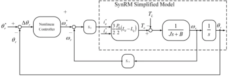
The block diagram of the closed-loop position control system is shown in Fig. 2. From Fig. 2, we can obtain
)
(
* * r v r p qK
K
i
=
ω
−
ω
(23)By substituting (23) into (3) and (4), we can derive
J
T
K
K
J
K
L r v r p t r=
−
−
•)
(
* 'ω
ω
ω
(24)Define the position error as
r r
e
θ=
θ
*−
θ
(25)
By taking the derivative of equation (25), we can obtain • • •
−
=
r re
θθ
*θ
(26)To obtain a nonlinear position controller, the control input of the position control system is selected as
r r xp r ip r ep e V G dt e e V G e e V G u ω ω ω ω θ θ θ ϑ θ ∂ ∂ + ∂ ∂ + ∂ ∂ = ( , )
∫
( , ) ( , ) (27)where
G
ep is the proportional gain of the position-loop controller,G
ip andG
xp are the integral gain of the position-loop controllers.In this paper, the Lyapunov function of the position control system is selected as [12]:
2 0 2 1 3 4 0 2 1 3 4 0 2 1 2 1 4 3 2 1 4 3 ) , (e r Kpe Kpe Kie Kie Kx r V ω = θ + θ + θ + θ + ω (28)
Substituting (28) into (27), we can obtain
+ + + + + + =G K K e G K K e G K K
∫
e dt u ep p i ep p i ip p i 3 1 0 0 1 1 3 1 0 0 ) ( ) ( ) ( θ θ θr x xp i p ip K K e dt G K G ( 1+ 1)
∫
θ + 0ω (29)In order to simplify the expression of (29), we define
) ( p0 i0 ep pnr G K K K = + (30) ) ( p1 i1 ep per G K K K = + (31) ) ( p0 i0 ip inr G K K K = + (32) ) ( p1 i1 ip ier G K K K = + (33) and 0 x xp xpr G K K = (34)
By substituting (30)-(34) into (29), we can derive the control input as r xpr ier inr per pnr r K e K e K e dt K e dt K u=ω = θ + θ+
∫
θ3 +∫
θ + ω 1 3 1 * (35)After that, the Lyapunov theorem is used to validate the stability of the position control system. We can take the derivation of the Lyapunov function and express it as
• • • • + + + + = p i p i x r r r K K e e K K e e K e V ω θ3 θ 1 1 θ θ 0ω ω 1 0 0 ) ( ) ( ) , ( (36)
By substituting (24) and (26) into (36), and doing some mathematical process, we can obtain
+ + + − + − = • r pnr t p x r i p r i p r J K e K K K e K K e K K e V ω θ ω θω θ3ω 1 ' 0 1 1 3 1 0 0 ) ( ) [ ( ( ) , ( ] ) 2 2 3 1 J T K K dt e K dt e K e K L r r v r xpr r ier r inr r per ω ω ω ω ω ω θ θ θ +
∫
+∫
+ − − (37) Next, by choosing ' 0 t ep p x K G K J K = (38)Then, substituting (38) into (37), we can obtain
) ( 1 ) , ( 31 2 2 ' t p r L r v r xpr r ier r inr ep r K K T K K dt e K dt e K G e V ω = ω
∫
θ + ω∫
θ + ω − ω − ω • (39)In this paper, we select
∫
+∫
+ + > 3 ' 1 t p L xpr ier inr v K K T K dt e K dt e K K θ θ (40)Substituting (40) into (39), we can obtain
(
)
0 ) ( 1 , ' 2 ' 2 3 1 2 3 1 ≤ − − + − + − =∫
∫
∫
∫
• t p r L r t p r L r ier r ier r inr r inr ep r K K T K K T dt e K dt e K dt e K dt e K G e V ω ω ω ω ω ω ω ω θ θ θ θ (41) Define 0 ) ( 1 ) ( ' 2 2 3 1 1 = ∫ + ∫ + − − ≤ t p r L r v r xpr r ier r inr ep KK T K K dt e K dt e K G t Z ω θ ω θ ω ω ω (42)By integrating (42), we can derive
))
0
(
),
0
(
(
))
(
),
(
(
)
(
0 1 r r te
V
t
t
e
V
d
z
τ
τ
=
ω
−
ω
∫
(43)Because
e
(
t
)
andω
r(t
)
are bounded, from equation (43), we can obtain∞
<
∫
∞ →z
τ
d
τ
t(
)
lim
1 (44) Becausez
1(
t
)
andz
1(
t
)
•are bounded, and
z
1(
t
)
is a uniform and continuous function. From Barbalet’s lemma, we can obtain( )
0
lim
1=
∞ →z
t
t (45)Combining (41) and (45), we can conclude that the proposed position control system converges to a zero steady-state error. As a result, the position control system is an asymptotically stable system. B Js+ 1 (Ld Lq) P − 2 2 3 0 * r θ r θ r θ Δ * q i * d i Te L T r ω * r ω r ω r θ s 1
Fig. 2 The block diagram of the proposed system IV. EXPERIMENTAL RESULTS
The proposed system uses a 32-bit digital signal processor, TMS 320C30, to determine the PWM switching states and execute the control algorithms. The dc bus voltage of the inverter is 150V. The sampling interval of the current-loop is 100
μ
s
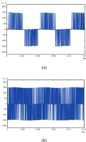
, and the sampling intervals of the velocity- and position-loop are 1ms, respectively. The motor is a 3-phase, 4 pole, rated speed 1800 r/min, 0.75hp. It was manufactured by the Reliance Electric Company. Several experimental results are shown here. Fig. 3 (a)(b) show the measured line-to-line voltage of the motor. Fig. 3(a) is the result of the proposed PWM control. Fig. 3(b) is the waveform of the bang-bang PWM control. As you can observe, the proposed PWM method has a lower switching frequency than the traditional bang-bang control. Fig. 4(a)(b) show the measured a-phase currents of the motor. Fig. 4(a) is the current waveform of the proposed control method and Fig. 4(b) is the waveform of the bang-bang control. The proposed method has lower harmonics than the bang-bang control. Fig. 5(a)(b) compare the switching conditions of the proposed method and bang-bang control. Fig. 6 shows the tracking performance of the torque. Again, the proposed method performs better than the bang-bang control although the proposed method has a lower switching frequency than the traditional bang-bang control.Fig. 7 (a)(b) show the measured responses of position and velocity of the nonlinear controller as the shaft of the
motor is controlled from 180 degrees to -180 degrees. Fig. 8 shows the load disturbance position response when a 2 N.m load is added. Fig. 9 shows the measured sinusoidal position responses of the nonlinear controller. It performs satisfactory again. 0 0.03 0.06 0.09 0.12 0.15 -200 -150 -100 -50 0 50 100 150 200 ,V Sec ab v (a) 0 0.03 0.06 0.09 0.12 0.15 -200 -150 -100 -50 0 50 100 150 200 ,V Sec ab v (b)
Fig. 3 the voltage
v
ab (a)proposed (b)bang-bang.0 0.03 0.06 0.09 0.12 0.15 -2.5 -2 -1.5 -1 -0.5 0 0.5 1 1.5 2 2.5 Sec ,A a i (a) 0 0.03 0.06 0.09 0.12 0.15 -2.5 -2 -1.5 -1 -0.5 0 0.5 1 1.5 2 2.5 Sec ,A a i (b)
Fig. 4 the current
i
a (a) proposed (b) bang-bang.2 3 4 5 6 7 8 9 10 11 5000 5500 6000 6500 7000 7500 8000 8500 9000 9500 10000 Bang-bang control Proposed method Current, A Switched times, count/s
(a) 2 3 4 5 6 7 8 9 10 11 0 5 10 15 20 25 30 35 40 Current, A Switching loss, Watt
Proposed method Bang-bang
control
(b)
Fig. 5 The switching conditions to different load. (a)switching frequency (b)switching loss.
0 0.01 0.02 0.03 0.04 0.05 0.06 0 1 2 3 4 5 6 7 8 Sec Torque, N-m Bang-bang current control Torque, N-m Proposed
Fig. 6 The torque responses.
0 0.1 0.2 0.3 0.4 0.5 0.6 -200 -150 -100 -50 0 50 100 150 200 Sec ,degree r θ (a) 0 0.1 0.2 0.3 0.4 0.5 0.6 -800 -700 -600 -500 -400 -300 -200 -100 0 100 200 Sec ,rpm r ω (b)
Fig. 7 The measured transient position responses (a)position (b) velocity. 0 1 2 3 4 5 6 0 50 100 150 200 250 Sec ,degree r θ
Fig. 8 The measured load disturbance response.
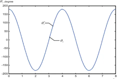
0 1 2 3 4 5 6 7 8 -200 -150 -100 -50 0 50 100 150 200 Sec * r θ r θ ,degree r θ
Fig. 9 The measured sinusoidal position responses VI. CONCLUSIONS
In this paper, a new PWM strategy and a novel control algorithm are proposed. The PWM strategy and the control algorithm are implemented by a 32-bit digital signal processor. As a result, the hardware is very simple and a fully digital control system is achieved. In addition, the proposed method can be applied to a position control system. Experimental results show that the proposed system has satisfactory performance and can be applied to a synchronous reluctance drive system.
REFERENCES
[1] M. P. Kazmierkowski and L. Malesani, “Current control techniques for three-phase voltage-source PWM converters: a survey”, IEEE Trans. Ind. Electron., vol. 45, no. 5, Oct. 1998, pp. 691-703.
[2] J. Holtz and B. Bayer, “Fast current trajectory tracking control based on synchronous optimal pulsewidth modulation”, IEEE Trans. Ind. Appl., vol. 31, no. 5, Sep./Oct. 1995, pp. 1110-1112.
[3] A. Vagati, M. Pastorelli, and G. Franceschini, “High-performance control of synchronous reluctance motors”, IEEE Trans. Ind. Appl., vol. 33, no. 4, July/Aug. 1997, pp. 983-991.
[4] S. J. Kang and S. K. Sul, “Highly dynamic torque control of synchronous reluctance motor”, IEEE Trans. Power Electron., vol. 13, no. 4, July 1998, pp. 793-798.
[5] M. T. Lin and T. H. Liu, “Design and implementation for a digital synchronous reluctance drive”, IEEE Trans. Aerospace and Electron. Syst., vol. 34, no. 4, Oct. 1998, pp. 1149-1164.
[6] K. K. Shyu and C. K. Lai, “Incremental motion control of synchronous reluctance motor via multisegment sliding mode control method”, IEEE Trans. Control Systems Technology, vol. 10, no. 2, Mar. 2002, pp. 169-176.
[7] H. D. Lee, S. J. Kang, and S. K. Sul, “Efficiency-optimized direct torque control of synchronous reluctance motor using feedback linearization”, IEEE Trans. Ind. Electron., vol. 46, no. 1, Feb. 1999, pp. 192-198. [8] S. E. Thanaa, W. D. Matthew, E. F. John, and W. W. Barry, “Nonlinear
robust control of a vector-controlled synchronous reluctance machine”, IEEE Trans. Power Electron., vol. 14, no. 6, Nov.1999, pp. 1111-1121. [9] M. S. Lin and T. H. Liu, “Design and implementation of a robust controller for a synchronous reluctance drive”, IEEE Trans. Aerospace Electron. Syst., vol. 37, no. 4, Oct. 1999, pp. 1344-1358.
[10]H. K. Chiang and C. H. Tseng, “Integral variable structure controller with grey prediction for synchronous reluctance motor drive”, IEE Proc.- Electr. Power Appl., vol. 151, no. 3, May 2004, pp. 349-358.
[11]K. K. Shyu, C. K. Lai, and J. Y. Hung, “Totally invariant state feedback controller for position control of synchronous reluctance motor”, IEEE Trans. Ind. Electron., vol. 48, no. 3, June 2001, pp. 615-624.
[12]S. E. Lyshevski, Control Systems Theory with Engineering Applications, Birkhauser, Boston: 2001.