中國水墨工筆畫之花卉合成
66
0
0
全文
(2) 中 國 水 墨 工 筆 畫 之 花 卉 合 成 The Synthesis of Chinese Fine-Brushwork Painting for Flower. 研 究 生:何怡緯. Student:Yi-Wei Ho. 指導教授:施仁忠. Advisor:Zen-Chung Shih. 國 立 交 通 大 學 資 訊 科 學系 碩 士 論 文. A Thesis Submitted to Institute of Computer and Information Science College of Electrical Engineering and Computer Science National Chiao Tung University in partial Fulfillment of the Requirements for the Degree of Master in Computer and Information Science June 2005 Hsinchu, Taiwan, Republic of China. 中華民國九十四年六月. II.
(3) 中國水墨工筆畫之花卉合成. 研究生: 何怡緯. 指導教授: 施仁忠 教授. 國立交通大學資訊科學系. 摘. 要. 工筆畫自盛唐以來即佔中國水墨畫中一重要席次,相對於寫意畫重意境,工 筆畫則強調細緻和寫實與色彩的應用,而工筆畫中主要分成人物畫和花鳥畫。本 篇論文即著重於工筆花鳥畫中花卉的畫法,輸入一張花朵的照片,經過與使用者 互動的模式,模擬出工筆畫中最重要的兩個步驟—勾勒和填彩。勾勒方面,透過 抓取影像的輪廓資訊,系統可以自動的產生出毛筆勾邊的效果。而填彩則利用假 想的畫家運筆路徑來模擬顏料的流動,並仿造工筆畫中多層渲染的技法。經由以 上兩道步驟,不需瞭解繁複的水墨畫技巧,也可以簡單的產生出含有工筆風格的 繪畫。. III.
(4) The Synthesis of Chinese Fine-Brushwork Painting for Flower. Student: Yi-Wei Ho. Advisor: Dr. Zen-Chung Shih. Institute of Computer and Information Science National Chiao-Tung University. ABSTRACT. The Chinese Fine-Brushwork Painting gets more and more important in the traditional Chinese Ink Painting since Tang Dynasty. Compared to Free Style Chinese Ink Painting, the Fine-Brushwork Painting puts emphasis on painting realistic, detailed, and the use of colors. It consists of two major categories: one is the Birds and Flowers Painting and the other is the Figure Painting. In this thesis, we focus on the flowers drawing in the former category. In our system, we simulate two important processes, sketching the contour(勾勒) and coloring (填彩). Input a photo of flower. We apply the brush strokes to the outline and simulate the pigment’s flowing paths to imitate multi-level coloring. Therefore, users may generate Fine-Brushwork Painting style easily by using our system without any painting skill. IV.
(5) Acknowledgements First of all, I would like to express respect to my advisor, Dr. Zen-Chung Shih. I greatly appreciate his patient teaching and guidance. Also, I am grateful to all members in Computer Graphics and Virtual Reality Laboratory for their help and friendship in these days.. I want to dedicate the achievement of this work to my family. Without their supports, I could not fully focus on my study. I also want to thank my friends who encouraged me during these days.. V.
(6) Contents ABSTRACT (in Chinese) ……………………………………………………………………………..III ABSTRACT (in English) ……………………………………………………………………………..IV ACKNOWLEDGEMENTS. .…......…………..…………………………………………………..…V. CONTENTS ......................................................................................................................................... VI LIST OF FIGURES............................................................................................................................VII LIST OF TABLES ............................................................................................................................... IX CHAPTER 1 INTRODUCTION........................................................................................................1 1.1 Motivation.................................................................................................................................1 1.2 System Overview .......................................................................................................................2 1.3 Thesis Organization ..................................................................................................................3 CHAPTER 2 RELATED WORKS ....................................................................................................5 2.1 Brush Model..............................................................................................................................5 2.2 Ink and Color Diffusion ............................................................................................................6 2.3 Non-photorealistic Rendering ...................................................................................................7 CHAPTER 3 PRELIMINARY OF CHINESE FINE-BRUSHWORK PAINTING.......................9 3.1 An Overview..............................................................................................................................9 3.2 The Painting Procedure .......................................................................................................... 11 CHAPTER 4 STROKE GENERATION .........................................................................................13 4.1 The Brush Model of Hon-Do Pen............................................................................................15 4.2 Sketching the Contour on Petal ..............................................................................................20 4.3 Sketching the Contour on Leaf................................................................................................26 4.4 Sketching the Contour on Pistil ..............................................................................................30 CHAPTER 5 WASHING ..................................................................................................................32 5.1 Washing Paths Generation......................................................................................................34 5.2 Washing Model........................................................................................................................36 5.3 Dimming Procedure ................................................................................................................44 CHAPTER 6 IMPLEMENTATION AND RESULTS ....................................................................45 CHAPTER 7 CONCLUSION...........................................................................................................54 REFERENCE .......................................................................................................................................56. VI.
(7) List of Figures FIGURE 1.1 THE SYSTEM FLOWCHART .......................................................................................................4 FIGURE 3.1 CREATIONS OF FINE-BRUSHWORK PAINTING ........................................................................10 FIGURE 3.2 THE WORK OF LIU YU HSIA .................................................................................................. 11 FIGURE 3.3 A PROCEDURE OF PAINTING ...................................................................................................12 FIGURE 4.1 THE FLOWCHART OF SKETCHING THE CONTOUR ....................................................................14 FIGURE 4.2 THE FOOTPRINTS OF CIRCLES (A) THIN (B) TIGHT .................................................................15 FIGURE 4.3 THE BRUSH MODEL ...............................................................................................................16 FIGURE 4.4 THE Ө REPRESENTATION ........................................................................................................17 FIGURE 4.5 EXAMPLES OF BRUSH MODEL ................................................................................................19 FIGURE 4.6 EXAMPLES OF CANNY EDGE DETECTOR ...............................................................................21 FIGURE 4.7 EXAMPLES OF STROKES ........................................................................................................21 FIGURE 4.8 EXAMPLES OF STROKE DEFINITION .......................................................................................23 FIGURE 4.9 EXAMPLES OF VECTORIZATION .............................................................................................24 FIGURE 4.10 EXAMPLES OF STROKE WITH DIFFERENT PARAMETER SETTING............................................25 FIGURE 4.11 EXAMPLE OF SKETCHING THE MAIN VEIN ............................................................................26 FIGURE 4.12 VEIN GENERATION ..............................................................................................................27 FIGURE 4.13 AN EXAMPLE OF SECONDARY VEIN GENERATION .................................................................28 FIGURE 4.14 EXAMPLES OF VEIN GENERATION ........................................................................................29 FIGURE 4.15 A HISTOGRAM ON HUE .........................................................................................................31 FIGURE 4.16 EXAMPLES OF VEIN GENERATION ........................................................................................31 FIGURE 5.1 FLOWCHART OF WASHING .....................................................................................................33 FIGURE 5.2 EXTREMITIES OF WASHING ....................................................................................................34 FIGURE 5.3 WASHING PATHS ....................................................................................................................35 FIGURE 5.4 WASHING MODEL ..................................................................................................................37 FIGURE 5.5 EXAMPLES OF WASHING WITH RANDOM RANDNUM BY THIGH=8, TLOW=3.............................39 FIGURE 5.6 PARAMETERS DETERMINATION..............................................................................................39 FIGURE 5.7 EXAMPLES OF WASHING BY (A) THIGH=13, TLOW=10 (B) THIGH=8, TLOW=3 (C) THIGH=3, TLOW=1 (D) THIGH=1.5, TLOW=1..................................................................................................41. FIGURE 5.8 EXAMPLES OF DIMMING PROCEDURE (A) GRAY-LEVEL IMAGE (B) DYED IMAGE (C) MIX BY 0.2*(A)+0.8*(B) ............................................................................................................................44 FIGURE 6.1 THE ORIGINAL IMAGE OF EXAMPLE 1 ....................................................................................46 FIGURE 6.2 (A) SUB-ORIGINAL IMAGE (B)(C) SKETCHING THE CONTOUR (D)(E) MULTI-WASHING BY TWO TIMES (F) DIMMING PROCEDURE ....................................................................................................46. VII.
(8) FIGURE 6.3 THE COMPOSITION OF FIGURE 6.2(C) AND (F) .......................................................................46 FIGURE 6.4 FINAL RESULT OF EXAMPLE 1 BY TWO TIMES WASHING .........................................................47 FIGURE 6.5 (A)(B)(C) MULTI-WASHING BY THREE TIMES (D) DIMMING PROCEDURE ................................48 FIGURE 6.6 FINAL RESULT OF EXAMPLE 1 BY THREE TIMES WASHING ......................................................48 FIGURE 6.7 THE ORIGINAL IMAGE OF EXAMPLE 2 ....................................................................................49 FIGURE 6.8 FINAL RESULT OF EXAMPLE 2................................................................................................50 FIGURE 6.9 (A)(B) MULTI-WASHING BY TWO TIMES (C) DIMMING PROCEDURE ........................................50 FIGURE 6.10 THE ORIGINAL IMAGE OF EXAMPLE 3 ..................................................................................52 FIGURE 6.11 FINAL RESULT OF EXAMPLE 3 ..............................................................................................52 FIGURE 6.12 (A)(B) MULTI-WASHING BY TWO TIMES (C)DIMMING PROCEDURE .......................................53. VIII.
(9) List of Tables TABLE 4.1 PARAMETERS IN CANNY EDGE DETECTOR..............................................................................20 TABLE 5.1 THE VALUES OF THRESHOLDS IN WASHING ..............................................................................40 TABLE 5.2 THE WASHING ALGORITHM .....................................................................................................43 TABLE 6.1 PARAMETERS OF EXAMPLE 1 ..................................................................................................47 TABLE 6.2 PARAMETERS OF EXAMPLE 2 ..................................................................................................51 TABLE 6.3 PARAMETERS OF EXAMPLE 3 ..................................................................................................53. IX.
(10) Chapter 1 Introduction. 1.1 Motivation Chinese Ink Painting has a long history in China. Painters use ink and water to create their compositions. After Tang Dynasty, Chinese Ink Painting divides into two parts: Free Style Chinese Ink Painting and Chinese Fine-Brushwork Painting. The former emphasizes that emotion is more important than shape. The artists use the characteristics of the relationship with ink, water and Hsuan paper to express their creations. Different from Free Style Painting, Fine-Brushwork Painting focuses on the object’s appearance. It depicts the object’s shape realistically and uses a great quantity of colors as a foil to it. Although the Free Style Painting becomes the main stream, Fine-Brushwork Painting still is a major part in Chinese Ink Painting.. In this thesis, we propose a system to synthesize realistic style of Chinese Fine-Brushwork Painting, specifically on flowers. Since the Birds and Flowers Painting is the main kind of Fine-Brushwork Painting, we focus on illustrating flowers. Although it already has complete background and mature procedure in painting, up to now, there are still few researches focusing on this topic. 1.
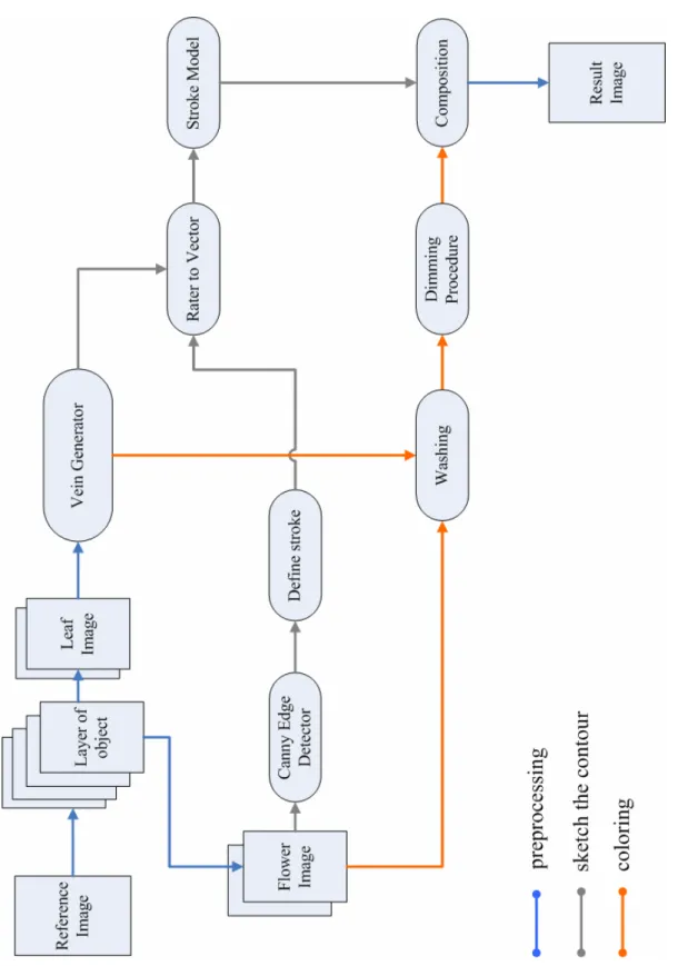
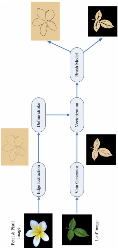
(11) 1.2 System Overview Figure 1.1 shows the flow of our proposed system. First, a user takes a flower image as a reference image. The user needs to separate it into different objects, such as a flower or leaves. There are slightly different procedures for different objects.. For a leaf image, we get it into the vein generator in the first phase. The user needs to specify the main vein by selecting several dots. Then, the system will generate other subsidiary veins automatically. In the second phase, it can be divided into two parts: sketching the contour and coloring. In the former, we apply a stroke style to each vein and to generate a drawing similar to Chinese Writing Brush. In coloring, we first generate the washing paths. These paths simulate the routes for brush when artists apply washing skill. Then, we suppose the flowing of color pigments by using exponential functions. The user can control the washing effect by adjusting proper parameters, for instance, the size of the brush and the quantity of the color pigments.. For a flower image, there are more steps to sketch the contours. The Canny Edge Detector [6] will find the edges in the image. The user can choose the edges they want to draw by using the parameters. Then, we establish stroke rules to define a stroke. When finding out all strokes, we use the same stroke model as we applied to leaf image to render the stroke style. In the coloring, it is also the same as before.. Finally, when all layers of object are completed, the composition of all the sub-image is the final result.. 2.
(12) 1.3 Thesis Organization This thesis is organized as follows. In chapter 2, we review the technique of computer-synthesized Chinese-Ink Painting in Non-Photorealistic Rendering. Then, we briefly introduce the features of Chinese Fine-Brushwork Painting in chapter 3. In chapter 4, we introduce the stroke model and the stroke generating procedure in detail. Chapter 5 describes the procedure for color diffusion. Then our implementation results are shown in chapter 6. Finally, chapter 7 is the conclusions and future works.. 3.
(13) Figure 1.1 The system flowchart. 4.
(14) Chapter 2 Related works. In this chapter, we discuss previous researches related to Chinese Ink Painting. We focus on two topics: the brush model, and the ink and color diffusion. Then, we also talk about the works which render an input image in non-photorealistic style.. 2.1 Brush Model In order to simulate the characteristics of real brushes, the researcher often needs to define an appropriate brush model. Strassmann [17] provided a fundamental model on this topic. He applies the physical properties of the real brush material in his model and well simulates the traditional Japanese art of sumi-e. His brush model is described by a one-dimensional array which sweeps along a spline curve. Suguru Saito and Masayuki Nakajima [15] also established a brush model for Japanese calligraphy and sumi-e paintings. But, it is a three-dimensional brush model which let the users can draw the strokes by using a pen-style input device. The same as Saito’s work, the DAB [5] project proposed an actual pen-style input device for users. It is more flexible in terms of brush shape, dynamics, and loading. It also can be implemented by three-dimensional graphics hardware. 5.
(15) The above techniques are for Western paintings or Japanese paintings. There are also several researches [7,19,20,21] simulating Chinese Writing Brush in Chinese Ink Painting. Shan-Zan Weng [19] introduced a two-dimensional brush model. He defined a variable circular area as the contact region of brush and canvas. In this area, the bristles are distributed uniformly. The center of the circle will move along the spline and sweep the footprints as the ink calligraphy on the canvas. He provided several types of brush, so the user can generate different kinds of stroke by selecting proper parameters. Wong and Ip [20] used an inverse cone to represent the virtual brush. They defined some interrelated parameters to change the density, opacity, and the shape of a footprint which corresponds to different behaviors of the brush.. According to the feature of Chinese Fine-Brushwork Painting, we define the brush model similar to Weng’s work in our system. Its advantages are easy implementation and well performance.. 2.2 Ink and Color Diffusion The effect of ink diffusion produced by the incredible absorbency of Hsuan paper is the most important feature of Chinese Ink Painting. So, several studies focused on this topic. [11,12,22] The technique proposed by Lee [12] rendered black ink paintings efficiently with realistic diffusion effects. It can simulate different kinds of diffusion depends on the kinds of paper or ink properties. But, it can not handle the blending effect of two or more strokes. Sheng-Wen Huang et al. [11] presented a method for simulating diffusion based on physical theory and analysis of observations. Their study discussed the relationship with water particles, carbon particles and Hsuan papers when the ink diffusing. They also contributed the expression of a mixture of. 6.
(16) different kinds of brush strokes, such as those of two wet brushes.. About color diffusion, in the DBA project [5], they used a simple alpha blending to show the color mixture. Curtis and Anderson [8] used Kubelka-Munk theory to simulate the effect of it. This theory studies the light reflection and transmission between pigments and paper. Another work that used KM theory is proposed by Wei-Jin Lin [13]. He employed KM model for the blending of traditional Chinese colors.. In this thesis, we use a new technique for synthesizing ink and color diffusion based on actual painting procedure and analysis of observations. Unlike the previous works of Chinese Ink Painting, we simulate the results of drawing on the alum Hsuan paper(礬宣)which is the particular material for Chinese Fine-Brushwork Painting.. 2.3 Non-photorealistic Rendering Researches in non-photorealistic rendering can be classified into two categories. The first one focuses on simulating and modeling the artist’s brushes. They often supply an interactive interface such as Painter [5,7,8,13,15,22] for users to create their compositions. The researches in this topic are described by section 2.1 and 2.2. The other [9,10,14,18,19] usually takes an image as the input and applies user-defined pattern or some filters of image processing in order to transform the input image into NPR styles.. Haeberli [9] proposed a stroke-based rendering technique with parameters control. These parameters describe properties of a stroke, such as color, length, width,. 7.
(17) and the location. Based on this technique, several researches are proposed to synthesize different NPR styles, for instance, a style of pencil drawing [14], oil painting [10] or Chinese ink painting [18,19]. Shan-Zan Weng [19] presented a system which inputs an existing Chinese Ink Painting image and re-paints it in other Chinese Painting styles. The system extracts the skeleton of the stroke automatically and applies a brush model with different style to it. In Chain-Ru Tang’s [18] work, it transformed an animal image into Chinese Fine-Brushwork style. It generates the hair drawing by using radial basis functions (RBFs) and makes use of mean shift filter to synthesize color diffusion.. In this thesis, we construct a system for the categories depicted before. Similar to Weng’s work, we take one image as the input and extract the skeletons and the colors on it. Then, we apply a brush model and color diffusion according to this information and then transform the image into Chinese Fine-Brushwork style.. 8.
(18) Chapter 3 Preliminary of Chinese Fine-Brushwork Painting. 3.1 An Overview Chinese Fine-Brushwork Painting has a long history. It began to develop from Epoch of Warring States until the Tang dynasty did it became mature enough to compare with the Free Style Chinese Ink Painting. However, during the Tang dynasty the Fine-brushwork Painting on Figure prevailed, a famous artist Zhou Fang’s work “Ladies wearing flowers”(周昉 『簪花仕女圖』) which depicted the real life with strong atmosphere of poetry. At that time the Birds and Flowers Painting was still in the initial stage. During the Five Dynasties, Huang Quan(黃荃) founded the groundwork of the Birds and Flowers Painting with sketching the contour doubly and coloring (”雙勾填彩”). And he also created the method to dye with multi-layer which means to dye repeatedly on the same location. (”三暈九染”) These techniques are still influential nowadays. Not until the Sung dynasty did Birds and Flowers Painting became mature and prosperous. Gorgeous and fine work was its characteristic, so it was taken seriously by the royal court such as Li Sung’s. 9.
(19) work “a flower basket” (李嵩 『花籃圖』). Between the Yuan and Ming Dynasties, the Literati Painting became the main stream. So it procured the decline of Fine-Brushwork Painting and the popularity of Free Style Painting on Birds and Flowers. But, it found a new way in the Ching dynasty. Influenced by the culture of Western, the Fine-Brushwork Painting developed a new style. It became more realistic, three-dimensional and vivid, because of the entering of Western Painting techniques, for example, the Lang Shining’s work “the Flowers”. (朗世寧 『聚瑞圖』)[2]. (a)“A flower basket” by Li Sung. (b) “The flowers” by Lang Shining [2] Figure 3.1 Creations of Fine-Brushwork Painting On the whole, Fine-Brushwork Painting emphasizes the reality of objects. Artists always work carefully and neatly with various colors. Therefore, they recently choose Hong-do pen (紅豆筆) which is composed of firm wolves’ hair. This kind of pen is quite suitable to draw delicate and flexible lines. They tend to choose pen with soft hair to dye with the technique of multi-layer. In the respect of using paper, paper of. 10.
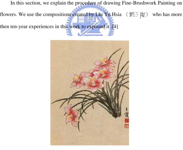
(20) Fine-Brushwork Painting is much different from that of Free Style painting. It adopts alum-Hsuan (礬宣) paper. It is one kind of Hsuan paper on which we brush a layer of alum. Because alum has immobility, alum-Hsuan paper does not be permeated by water easily and it does not make the ink diffuse. Therefore, it is quite suitable for Fine-brushwork Painting with several times of dyeing.[3,4]. In this thesis, we focus on the equipments’ characteristics of the Fine-Brushwork Painting which are the Hong-do pen and the alum-Hsuan paper.. 3.2 The Painting Procedure In this section, we explain the procedure of drawing Fine-Brushwork Painting on flowers. We use the compositions created by Liu Yu Hsia (劉玉霞) who has more then ten-year experiences in this work to expound it .[4]. Figure 3.2 The work of Liu Yu Hsia The process of Fine-Brushwork Painting is divided into two types: sketching the 11.
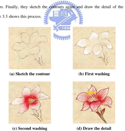
(21) contour and coloring.[1,2] First, painters draw the outline of the flower by using pale ink. It is the draft of the composition. Next, they use washing technique (”渲染”) which is a traditional skill of Chinese Painting to dye the objects. For washing, painters use two brushes that one is soaked in water and the other is soaked in colors. Painters employ the colored pen to dye the color inside the lines. Then, they extend it inside out by using the watered pen. It causes the color decreasing bit by bit from inner to outer and makes the color vary plentifully. In the Fine-Brushwork Painting, washing is the major skill for coloring. Painters use it to dye layer by layer and let the creations colorful. For instance, in flower coloring, painters usually apply it two or more times with different colors. Painters may apply it from the petals to the pistils with white color first, then use it again inversely with the color depending on the flowers. Finally, they sketch the contours again and draw the detail of the objects. Figure 3.3 shows this process.. (a) Sketch the contour. (b) First washing. (c) Second washing. (d) Draw the detail. Figure 3.3 A procedure of painting 12.
(22) Chapter 4 Stroke Generation In this chapter, we describe how to obtain the stroke information from input image and use it to sketch the contour in the style of Chinese Fine-Brushwork Painting. We introduce our proposed brush model first, and then discuss it from three parts: the petal, the leaf and the pistil. Figure 4.1 shows the flowchart of sketching.. In Chinese Fine-Brushwork Painting, sketching the contour is the first step of all. First, Painters draw the shapes and positions of objects realistically by using pale ink. It is the draft for dyeing. Then, after dyeing, they sketch the contours again by using thick ink or any other preferred color. It may make the creations more vivid. The Hong-do pen(紅豆筆)is the equipment in common use for this procedure. So we simulate our brush model for the Hong-do pen style.. This chapter is organized as follow. In section 4.1, we talk about our proposed brush model that is based on the Hong-do pen style. Then, we describe the part of flower in section 4.2 that contains the edge extraction, the stroke definition, and the brush model execution. Section 4.3 explains the generation of veins. In the section 4.4, we introduce how the pistil drawing and its color determination.. 13.
(23) Figure 4.1 The flowchart of sketching the contour 14.
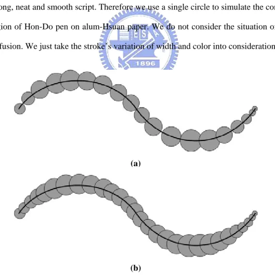
(24) 4.1 The Brush Model of Hon-Do Pen In the field of Chinese Fine-Brushwork, artists use tapering and flexible Hon-Do pen. In this section, we explain how we simulate the characteristics of Hon-Do pen.. Hon-Do pen has the characteristics of stiffness and taper. Furthermore, the alum-Hsuan paper has the feature that water absorption is low and the ink does not diffuse easily. So, in sketching of Chinese Fine-Brushwork Painting, Hon-Do pen can generate clear and obvious lines. Lines seldom have the situation of diffusing. In the respect of drawing(運鋒), artists often sketch with Chung Feng skill(中鋒). It means that artists place the tip of pen in the middle without any slanting to make sound, strong, neat and smooth script. Therefore we use a single circle to simulate the contact region of Hon-Do pen on alum-Hsuan paper. We do not consider the situation of ink diffusion. We just take the stroke’s variation of width and color into consideration.. (a). (b) Figure 4.2 The footprints of circles (a) Thin (b) Tight 15.
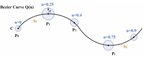
(25) Figure 4.3 The brush model We define a circle which changes the radius along the variation of tangent line to represent the contact surface of Hon-Do pen on alum-Hsuan paper. This circle will move along a curve and sweep the footprints as the ink calligraphy on the canvas. Consider Figure 4.2, when the contact circles are close enough, the whole footprints seems like a brush painting stroke. Figure 4.3 shows a curve depicted by Bezier polynomial. We may define a contact circle C with radius r, Pi is the point generated by substituting u i into the Bezier polynomial Q (u ) , S1 and S 2 are the thresholds of the curve’s two extremities to restrict the circle C’s variation on them. We define:. ( kθ ) ⎧ if S1 < u i < S 2 ⎪base + m , ⎪⎪ ( kθ ) ri = ⎨ start → base + , if u i ≤ S1 ………………… (4.1) m ⎪ ⎪base + ( kθ ) → 0, if u i ≥ S 2 ⎪⎩ m. where the variables mean: 1. ri : the radius of circle C at point Pi .. 16.
(26) 2. base: the minimum radius of circle C. It presents the minimum width of the Hon-Do pen stroke. 3. start: the initial radius of circle C. It presents the initial pressure when drawing. 4. θ : the included angle of adjacent points’ tangent lines as shown in Figure 4.4. 5. k: an adjustable degree for angle θ . 6. m: the u’s unit variation. It means the disparity between u i and u i +1 .. Figure 4.4 The ө representation Consider Eq.4.1, when the value of u i lies between S1 and S 2 , the width of line depends on the variation of the line’s curvature. In real painting, artists usually draw heavier to generate thicker stroke when the line’s curvature becomes larger. So, we produce this effect by using the variable θ . The larger the included angle θ the greater the line’s curvature. So we will obtain wider lines, and vice versa. We can also adjust the influence of angle θ by the parameter k. Then, we let the equation divide by m to decrease the effect of different disparity between u i and u i +1 . If we assign smaller disparity of u, it will cause smaller θ . That will affect radius r indirectly. In other words, if parameter m does not exist, we may get different widths of stroke when the u’s unit variation is different. But it is not a reasonable result, we use the variable m to avoid it. When u is smaller than S1 , we simulate the effect of initial drawing. The radius r increases from start to the radius of point S1 . The radii 17.
(27) between P0 and. PS 1 are generated by blending start and rS 1 . On the other hand,. when u is greater than S 2 , we decrease radius r from rS 2 to 0. It simulates the ending of the stroke when painting.. So, after all parameters are determined, we set a very small disparity of u. Then we can draw many circles with various radii and let them as the footprints of the ink calligraphy to obtain the goal of simulating Hon-Do pen style.. In respect of color’s variation, artists always use brushes full of ink to sketch. So we will not obtain the effect of dried pen(乾筆). But the ink still could distribute non-uniformly, and it will fade away gradually. In our proposed model, we obtain this effect by adjusting the intensity of the color. The user can choose the color they like. Then, the system will transform it from the RGB domain to HSI domain. When drawing, we raise the intensity of the color and let it change pale smoothly. In order to make non-uniform color, we cut circle C into several parts, then apply colors with slightly different intensity to each part. Then, we use a smooth filter on the stroke to make it vary smoothly and naturally. Figure 4.5 shows results of our proposed brush model.. 18.
(28) (a) Original line. (b) Stroke by start=1.0, base=2.0, k=0.2, S1 =0.2, S 2 =0.8. (c) Stroke by start=8.0, base=3.0, k=0.4, S1 =0.1, S 2 =0.8. Figure 4.5 Examples of brush model. 19.
(29) 4.2 Sketching the Contour on Petal In this section, we introduce the procedure for sketching the contours on flower’s petals according to the input image.. 4.2.1 Edge Extraction We use Canny edge detector to find the silhouettes in an image. The Canny edge detector is a well-known algorithm. It uses the gradient of color in an image to determine the location of lines and find continuous and single-pixel-wide lines. User may input three parameters to decide the output line’s delicacy and importance, as shown in Table 4.1. The full and detail algorithm can be found in [6].. Parameter. Function. δ. The parameter of Gaussian smooth filter used to eliminate the noise in input image.. high. The upper threshold. If the magnitude of a pixel is larger than high, it will be considered as an edge pixel.. low. The lower threshold. If the magnitude of a pixel is smaller than low, it will be considered as a non-edge pixel. If the value of a pixel is between high and low, it is determined by the connection. Table 4.1 Parameters in Canny Edge Detector. In our proposed system, the user can use proper parametric values to exclude unnecessary detail information and obtain appropriate lines. Since the goal of this step is to sketch the contours, the lines which can show the outlines of petals have higher priority.. 20.
(30) (c)δ=1.2,low=0.6,high=0.8 (a) Original image (b)δ=1.2,low=0.6,high=0.9 Figure 4.6 Examples of Canny Edge Detector. 4.2.2 Stroke Definition After the edge extraction, we obtain a group of edge pixels. But we can not decide which points will form a stroke. In Chinese Fine-Brushwork Painting, artist sketches a line once based on the shape of the object. Consider Figure 4.7, an artist will draw a stroke for a petal, or draw two symmetric strokes for it, etc. Therefore, we have to group these pixels into strokes.. (a) One stroke for a petal (b) Two strokes for a petal Figure 4.7 Examples of strokes.. 21.
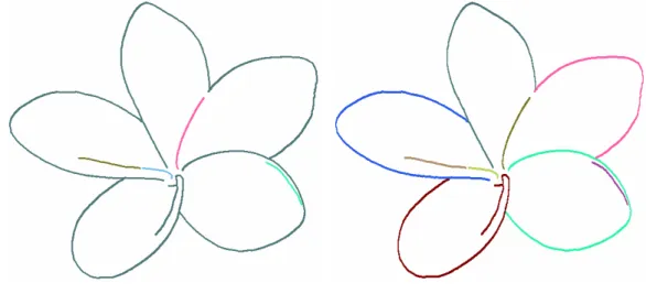
(31) We first make judgments of connection to link points in neighborhood. We hypothesize that the connected pixels belong to one stroke. To avoid the disconnections generated by Canny Edge detector, we assume pixel in a 5×5 window to be connected. We choose a 5×5 window to define connection by our experience. The window of 3×3 squares makes too many disconnected strokes, and the 7×7 window causes some unnecessary connections. But, the connection defined by a 5×5 window still causes many unreasonable linking lines as shown in Figure 4.8(a). Pixels in the same color are considered as a connection. So we have to cut off or eliminate some unsuitable connections according to the following rules:. 1. The pixel whose links are less than X pixels will be eliminated. The default value of X is 30, which can be changed by user. Its goal is to avoid too short lines or lines interfered by noise. 2. The lines which are closed connected into a stroke in pistil area will be eliminated. Pistil area is a region selected by user. Because the procedure of pistils is different from that of petals, we eliminate the pistil’s lines to avoid them being redrawn. The method of the pistils will be discussed in section 4.4. 3. If two connected pixels accumulate the variation of gradient’s direction more than 90 degrees, we have to cut it off. The direction of color gradient can be obtained by Canny edge detector. This rule mainly cuts off the connection between two petals.. By applying the above rules, we will get more reasonable and suitable strokes. The result is shown in Figure 4.8(b), and pixels in the same color are considered as a stroke.. 22.
(32) (a) After applying connection. (b) After applying stroke definition. Figure 4.8 Examples of stroke definition. 4.2.3 Vectorization The goal of vectorization is to let pixels of a stroke be represented by a polynomial. Therefore, we can definitely know the stroke’s starting point, ending point and the tangent line’s gradient. This field has developed well, so we do vectorization based on Schneider’s work [16].. The input of this algorithm is a group of sequential pixels. Then, it will output several Bezier curves to approach the inputs depending on user’s tolerated error. This algorithm mainly use a least-squares fitting method in mathematics to generate the four control points of a cubic Bezier curve. First, we generate one curve to approach the input pixels. If this generated curve is far away from the original inputs, we take out the pixel p that has the largest error. Then subdivide the inputs by p into two sequences of pixels. For each sequence, we generate a Bezier curve to approach it. However, if the error is still too large, we continuously subdivide it into two 23.
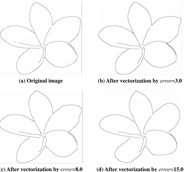
(33) sequences and generate approximated curve for each. The above process will recursively subdivide pixels into two sequences until acceptable curves are generated.. When an artist is sketching, he does not depict a flower’s contour carefully. If he draw a flower’s contour exactly, this flower will look awkward without flexibility. A smooth curve can show the resilience of a flower. So, we can not generate vectorized stroke too exactly. In order to obtain this effect, we can not set too small error range, as shown in Figure 4.9.. (a) Original image. (b) After vectorization by error=3.0. (c) After vectorization by error=8.0. (d) After vectorization by error=15.0. Figure 4.9 Examples of vectorization. 24.
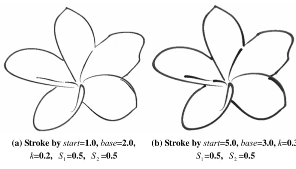
(34) 4.2.4 Apply Brush Model After vectorization, we apply the brush model to generate each stroke. User can define appropriate parameters, or use the default values offered by the system, as shown in Figure 4.10.. (a) Stroke by start=1.0, base=2.0, k=0.2, S1 =0.5, S 2 =0.5. (b) Stroke by start=5.0, base=3.0, k=0.3 S1 =0.5, S 2 =0.5. Figure 4.10 Examples of stroke with different parameter setting. 25.
(35) 4.3 Sketching the Contour on Leaf In this section, we introduce the generation of veins. The users need to specify the primary vein. Then the subsidiary veins will be generated automatically. Finally, we apply the brush model to each vein.. 4.3.1 Sketching the Main Vein First, the user needs to specify the primary vein. From this, we can obtain the direction and the curvature of this leaf. User does not need to specify the primary vein’s position carefully but only to select several dots, as shown in Figure 4.11, the red points are selected by user. Then, we produce a fitting curve to approach them.. Figure 4.11 Example of sketching the main vein. 4.3.2 Vein Generation In this thesis, we produce the secondary veins by using primary vein’s information. So there may have slight disparity from the original image. First, we approximate the primary vein with a Bezier curve. Then we can get some information of this leaf, such as length, curvature, and so on. We use this information to generate. 26.
(36) secondary veins.. Figure 4.12 Vein generation Consider Figure 4.12, curve Q is the primary vein and we want to generate secondary veins Qi , i = 0,1,2,..,n-1. θ is the rotation angle defined by user. n is the amount of secondary veins defined as follows:. ⎧ ⎪ ⎪ 3, if dist ( S − E ) ≤ X ⎪ n=⎨ ⎪ dist ( S − E ) − X + 3, else ⎪ X ⎪ 3 ⎩ where dist (S-E) means the distance between curve Q’s two extremities, S and E. The default value of parameter X is 60, but it can be adjusted by user. It affects the interval between adjacent Pi . We divide the curve Q equally into n curve segments with points Pi , i=0,1,2…,n-1. Then, we select the point Pi , i=0,1,2…,n-1, P0=S, as the root of secondary vein Qi . For example, as shown in Figure 4.12, the number of n is 4. We want to generate veins Q0, Q1, Q2, Q3 and their roots are P0, P1, P2, P3. In order to avoid too uniform veins, we adjust the location of Pi slightly by shifting a small random distance.. When we produce the vein Qi , the method is to copy a segment Mi of the 27.
(37) primary vein Q. The segment Mi begins at point Pi , and it is 1.2 times the length of Pi ’s interval. Then, we use point Pi as the pivot point of rotation and rotate Mi with angle θ . If Mi’s direction to the curvature center Vi faces the location of Qi , we mirror Mi before rotating it. Otherwise, if Qi is in the counter side of Vi, we rotate Mi directly. Then, we assign the rotated Mi for Qi . We describe this method by the example as shown in Figure 4.13.. Figure 4.13 An example of secondary vein generation. Consider Figure 4.13, M i is a segment copy from primary vein and its direction to the curvature center is vector V. When generating Q1 , we consider the relation between V’s direction and Q1 ’s location. Since Q1 is in the reverse direction of V, we rotate M i around Pi with θ. counterclockwise. When. generating Q2 , we consider the relation between V and Q2 . Because of V’s direction, we need to reflect M i by the line L and rotate it around Pi with angle θ clockwise. Then we assign the rotated segment M i for the secondary vein. This method ensures that the secondary vein Qi ’s curvature is equal to the primary vein and its direction to the curvature center always faces the primary vein. We can obtain more reasonable and natural veins. Finally, when drawing the secondary veins, we restrict that the adjacent Qi should be on the different sides of the primary vein. For 28.
(38) the third and further levels of veins, we apply the same process recursively to generate veins level by level. After obtaining the veins, we apply the brush model to them. Artists usually draw a stroke heavily near the steam or leaf’s center, and slightly when close to the tip of a leaf. So, we set a larger value for the parameter start and a smaller value for the parameter base to achieve this effect. Figure 4.14(a) shows the result of Figure 4.11, and 4.14(b), 4.14(c) show other results of secondary veins at different levels. The red points on the primary veins are selected by user.. (a) level=2, ө=35 . (b) level=3, ө=35 (c) level=4, ө=35 Figure 4.14 Examples of vein generation. 29.
(39) 4.4 Sketching the Contour on Pistil We describe the procedure of generating pistil in this section. First, we use the process similar to section 4.2 to produce the pistil’s strokes. Then, the clustering algorithm will provide the colors which approximate the colors in input image.. 4.4.1 Stroke Generation In our proposed system, users need to specify the pistil area by dragging an ellipse. Then, this pistil image is the input of the following process. First, we use the Canny Edge Detector to extract its edges. Since artists usually draw exquisitely for pistil, we choose the lower thresholds than petal’s to get more detailed information. Then, we define strokes similar to that in section 4.2.2. We change the second restriction to eliminate the lines which are connected outside the pistil area. Since these lines do not belong to the pistil, we have to avoid them being mistakes. After defining strokes, we apply the vectorization and brush model to them.. 4.4.2 Color Determination Unlike strokes of petal, painters draw pistils with more colors. So we use a simple color clustering algorithm to determine the colors. User can decide the amount of preferred colors by adjusting the parameter num. Then, the system will select num colors which appear mostly in pistil area as reference colors. When drawing a stroke, we calculate the disparities between these reference colors and the realistic color at the same stroke in the input image. Then, we choose the most similar color to dye this stroke.. 30.
(40) Figure 4.15 A histogram on hue In color clustering algorithm, we firstly follow all drawing strokes and select the pixels at the same position in the input image. Then, transform the color of these pixels from the RGB domain to HSI domain to establish a histogram on H. The values of H are classified into ten subdivisions as shown in Figure 4.15. We choose the highest num colors as reference colors. The S and I components of reference colors are assigned by the average of S and I in the same subdivision. When drawing a stroke, we extract the colors in input image of all points that lie on this stroke. Calculate their average in RGB domain. Then, select a reference color which has the minimum difference from their average color to dye this stroke. Figure 4.16 shows the experimental result.. (a) Original image. (b) Pistil area and reference colors. (c) Generated pistils. Figure 4.16 Examples of vein generation 31.
(41) Chapter 5 Washing In this chapter, we discuss the dyeing effect in our system. First, we get the color information from input image. Then, we simulate the washing technique that is a traditional skill in Chinese Fine-Brushwork Painting. Finally, we blend the resulting image and the stroke image. Figure 5.1 shows the flowchart of washing.. In Chinese Fine-Brushwork Painting, coloring is the procedure following the contour sketching. Washing is the most important skill for coloring. Painters often apply washing technique several times to make the creation colorful and smooth. It may have different moving direction and dyeing color in each time of washing.. In section 5.1, we talk about the washing paths generation that simulate the dyeing paths for a brush. Then, we depict our proposed washing model in section 5.2. It contains the dyeing algorithm, parameters determination, and the mixture of colors. In section 5.3, we introduce the dimming procedure.. 32.
(42) Figure 5.1 Flowchart of washing 33.
(43) 5.1 Washing Paths Generation This section introduces how the washing paths be generated. The washing paths simulate the routes when artists apply washing skill by using watered pen. We will dye along these paths when applying washing. First, users need to specify an area for dyeing. Then, the system will generate the washing paths automatically.. 5.1.1 Extremities of Washing Before starting washing, users need to specify the starting and ending points. Users need to specify one starting point and several ending points. Since painters always washing from pistil to petal, we set the starting point at the pistil and ends at the petal as shown in Figure 5.2. Naturally, user can set the points anywhere, and the system will apply washing technique on the specified area.. Figure 5.2 Extremities of washing. 5.1.2 Washing Paths Generation According to the user-specified starting and ending points, we can generate the paths of washing. Artists often use colored pens to apply dyestuff on the center of flower, and then they may use watered pens to dye from the center to the petal. We just simulate the paths of watered pens. 34.
(44) Figure 5.3 Washing paths Figure 5.3 shows the grey area where we want to dye. The points Ustart and Uend are the starting and the ending point. We trisect the line. U startU end. to get points U1. and U2. The purpose of trisection is to let these four points Ustart, U1 , U2 and Uend be the four control points of a Bezier curve. Then, we fix the point Ustart and move other points U1, U2 and Uend in the vertical direction of line. U startU end. . The length of. moving is preset in the system. Therefore, through the new points we get and the fixed point Ustart, we can obtain a new set of Bezier curve’s control points. Consider Figure 5.3, Bezier curve Qi’s control points are Ri,0 , Ri,1, Ri,2, Ri,3. Thus, we will get a new Bezier curve when we move three points in the vertical direction. As painting area is covered by all curves, the system will stop to generate Bezier curves automatically. At this time, all the curves are the watered pen’s paths that we anticipate as the dotted line in the Figure 5.3.. 35.
(45) 5.2 Washing Model This section introduces how we simulate the traditional dyeing technique “washing” (渲染)of Chinese Fine-Brushwork Painting. Our model is based on the actual painting procedure and observations. We imitate the procedures of painting and apply several methods in image processing to synthesize the result of washing. First, washing paths are constructed as discuss in section 5.1. Then, when the brush sweeps along the washing paths, we may apply an exponential function to simulate color diffusion. Finally, we mix the color pigments with background color to produce the result.. 5.2.1 Washing by Water Pen There are pigments in colored pen when washing. Watered pen just delivers water for pigments diffusion. In our proposed model, we combine the colored and watered pens and apply pigments on the watered pen directly.. It is different from sketching the contour. Since the brush for washing is softer than Hong-do pen, we use an ellipse to model the contact region of watered pen on alum-Hsuan paper. For easy of implementation, the size of ellipse is fixed. Figure 5.4(a) shows the contact region C. Variables a and b are the major axis and minor axis respectively.. Ellipse C will move along the washing paths and sweep the footprints as the color calligraphy on the canvas. It is similar to the brush model described in Chapter 4. But, it is a little difference. Ellipse C will rotate when moving along the path. Consider Figure 5.4(b). Qi is a washing path and Pk is a point on it. When C move 36.
(46) forward along Qi, it will aim its y-axis at the direction of point Pk’s tangent on the curve.. (a) Contact surface. (b) A path for washing Figure 5.4 Washing model. When C moves along with Qi, C will leave pigments on the canvas. We hypothesize that every point has its capacity. We set pigment 100 is full, 0 is empty. When C passes though Pk, we will decide how much percentage of pigments to leave by C according to an exponential function. That is a method which we figure it out by observing artists’ washing.. To implement this method, we set two thresholds tLow and tHigh. They will influence dyeing color’s variation. Then, we pick a random number r between these two thresholds. Variable r is the power of the exponential function as shown in Eq 5.1. We pick 100 points P on curve Qi. It means ellipse C will cover Qi one hundred times. Nall is the total pigment number on the brush. The pigment number NPk that C left on Pk is:. 37.
(47) Np. k. =. (100 − k ) r × N all , k ∈ j 99 r ………………….…..….. (5.1) ∑j j =0. In Eq5.1, when setting a larger r, the exponential function will vary sharply. Then, we may get intensely variation of color. In other way, if we have a smaller number of r, we generate color variation smoothly. The number of r is controlled by thresholds tLow and tHigh. We can adjust them automatically according to the input image. The detail procedure of their determination will be depicted in next section.. When C leaves a footprint on Qi, we divide NPk equally by the amount of pixels in C and set it to the quantity of these pixels’ pigment. If it exceeds the capacity of pixel, we set it the maximum of capacity. After C passes by one Qi, system will compare the pigment distributed on Qi with the pigment on Qi-1. If the pixel on the same position already has some pigments in previous step, the more will be selected and will remain instead of adding them together. We suppose that watered pen will take some pigments away when pigment’s quantity of a pixel is too high. It avoids the situation that pixels are always at the state of saturation. In addition, to avoid that every curve Qi uses the same exponential function, this situation will lead to the result of being too smooth. So, we choose random number on every Qi again to decide variable r, the power of every exponential function. Figure 5.5 shows examples of washing.. 38.
(48) Figure 5.5 Examples of washing with random randnum by tHigh=8, tLow=3. 5.2.2 Parameters Determination When applying washing, we need to determinate three parameters, tHigh, tLow, Nall. The last one is specified by users because it depends on the consistency of color pigment they want to dye. But parameters tHigh and tLow, can be decided by color variation of the input image.. Figure 5.6 Parameters determination 39.
(49) As shown in Figure 5.6, the blue one is the area we want to dye. The points Ustart and Uend are the starting and the ending point. We divide line. U startU end. into. four parts equally by points U1, U2 and U3. Then, we separate them into two groups, colorstart and colorend, by comparing their color in input image. We calculate the color disparities separately between Ui and Ustart, Ui and Uend. If Ui’ color is close to Ustart’s, set Ui in the group of colorstart, and vice versa. After all points are assigned, we can find the boundary of two groups, such as the line L in Figure 5.6.. Since L corresponds to the color changed sharply in input image, we determine thresholds tHigh and tLow according to L’s position. If L is close to point Ustart , we set a large thresholds to obtain dyeing color vary sharply near Ustart and vice versa. The following List 5.1 shows the values of tHigh and tLow and Figure 5.7 shows their influence. L position. value of tHigh. value of tLow. between Ustart and U1. 13. 10. between U1 and U2. 8. 3. between U2 and U3. 3. 1. 1.5. 1. between U3 and Uend. Table 5.1 The values of thresholds in washing. 40.
(50) Figure 5.7 Examples of washing by (a) tHigh=13, tLow=10 (b) tHigh=8, tLow=3 (c) tHigh=3, tLow=1 (d) tHigh=1.5, tLow=1. 5.2.3 Color Mixture Every time after simulating the effect of washing, we will start to do the color mixture. In our system we take Subtractive Color Mixture to model the overlapping of color. In section 5.2.1 we got an image with the distribution of color pigments. We still map the pigments’ quantity to color. We set the color of canvas as the background color such as yellowish brown. Because the capacity of pigment is 100, the full pigment (100) will totally cover the background. It will show the color which we want to dye. If the pigment is less than the full capacity, the percentage of pigment will determine the degree of color mixture. As Eq 5.2 shown below, Nx,y is the pixel’s quantity of pigment, colord is the color which we want to dye, and colorb is the background color. The pixel’s color colorx,y will be:. color x , y =. N x, y 100. × color d + (1 −. 41. N x, y 100. ) × color b …………………….(5.2).
(51) Since the process washing will be performed several times, we let the current pixel’s color be the background for the next washing process. Therefore, we can achieve the goal of multilayer color mixture. List 5.2 shows the algorithm of washing.. 42.
(52) Washing Algorithm Input: ------------------------------------------------------------------------------------CloseSetClas area /* painting area and washing paths */ ImageClass inputImg /* background image */ Color col /* dyeing color */ /* quantity of pigment in watered pen */ Int Nall Double tHigh, tLow /* thresholds of exponential function */ Output: ------------------------------------------------------------------------------------ImageClass outputImg /* washing image */ ----------------------------------------------------------------------------------------------void Washing() initial… for (every path Qi in area). /* set watered pen */. r =Exponential(tHigh, tLow); for (every points Pk through path Qi , k=0~99) Np. k. =. (100 − k ) r × N all , k ∈ j 99 r j ∑ j =0. ;. for(every points x in watered pen ) rotate the mask of watered pen, aim its y-axis at Pk ’s tangent; Nx = ( NPk / watered pen.size)+ Nx ; Nx =FULL; if( Nx >FULL ) for (every point (x, y) in outputImg ) if( Nx,y > outputImgx,y ) outputImgx,y = Nx,y; colorMixture(inputImg, outputImg, col ); smoothFilter(outputImg);. Table 5.2 The washing algorithm. 43.
(53) 5.3 Dimming Procedure After washing, we apply a dimming procedure to let the color approach traditional Chinese colors.. Since we washing with the color obtained from input photograph, the color is too brighter to simulate the traditional Chinese colors. Unlike Western Painting, Chinese painters usually use sober color to present implicit and gentle mind. Furthermore, the material of Chinese color is made by minerals or plants, so most of all are turbid and dim. To achieve this effect, we mask a gray-level image on the dyed image. We transform original input into gray-level image, and mix the dyed image with it in the ratio 8:2, as shown in Figure 5.9.. Finally, when all washing procedure is completed, the combination of sketched images and dyed images is the final result. We show them in the next chapter.. Figure 5.8 Examples of dimming procedure (a) Gray-level image (b) Dyed image (c) Mix by 0.2*(a)+0.8*(b). 44.
(54) Chapter 6 Implementation and Results In this chapter, the implementation and results are presented. The input sources are colored photographs and users need to separate them into different objects by painting software. The algorithm are implemented in C++ language on BCB with an AMD XP 2500+ CPU and 512MB DDR RAM.. Example 1 is a 800×600 image as shown in Figure 6.1. Figure 6.2 shows the intermediate results of sketching the contour and multi-washing. 6.2(a) shows the partial original image. Its extracted contours are shown in 6.2(b), and 6.2(c) shows the result after applying the brush model to it. Figures 6.2(d)-(f) show the intermediate results of multi-washing procedure. We first use washing skill from petal to pistil as shown in Figure 6.2(d). Then, use it again inversely as shown in 6.2(e). Finally, Figure 6.2(f) shows the result after dimming procedure. Figure 6.3 is the composition of Figure 6.2(c) and (f). The final result of this example is shown in Figure 6.4 and the corresponding parameters are displayed in Table 6.1. Figures 6.5 and 6.6 show the other results of washing by different times.. 45.
(55) Figure 6.1 The original image of example 1. Figure 6.2 (a) Sub-original image (b)(c) Sketching the contour (d)(e) Multi-washing by two times (f) Dimming procedure. Figure 6.3 The composition of Figure 6.2(c) and (f). 46.
(56) Figure 6.4 Final result of example 1 by two times washing. procedure. parameters Sketching the Contour. Canny Edge Detector. high=0.9, low=0.6, δ=1.2. Stroke Definition. X=50. Vectorization. error=8.0. Brush Model. start=1.0, base=2.0, k=0.2, S1=0.5, S2=0.5 Multi-Washing. First Washing tHigt=8, tLow=1 from petal to pistil Nall =1500000 (showed in Figure6.2(d)) colord =RGB(229,243,254) (selected by Uend’s color ) Second Washing tHigt=8, tLow=3 (automatically generated by 5.2.2) from pistil to petal Nall =1500000 (showed in Figure6.2(e)) colord =RGB(233,217,104) (selected by Ustart’s color ) Third Washing tHigt=8, tLow=5 from pistil to petal Nall =1000000 (showed in Figure6.5(c)) colord =RGB(179,145,53) Table 6.1 Parameters of example 1. 47.
(57) Figure 6.5 (a)(b)(c) Multi-washing by three times (d) Dimming procedure. Figure 6.6 Final result of example 1 by three times washing 48.
(58) Example 2 is a 600×800 image as shown in Figure 6.7, and Figure 6.8 shows its final result. Figure 6.9 shows its intermediate results of washing. Figure 6.9(a) shows the result of washing from petal to pistil, and 6.9(b) shows the washing result from pistil to petal, and the result of dimming procedure is shown in (c). The corresponding parameters of this example are displayed in Table 6.2.. Figure 6.7 The original image of example 2 49.
(59) Figure 6.8 Final result of example 2. (a) (b) (c) Figure 6.9 (a)(b) Multi-washing by two times (c) Dimming procedure. 50.
(60) procedure. parameters Sketching the Contour. Canny Edge Detector. high=0.82, low=0.4, δ=0.8. Stroke Definition. X=20. Vectorization. error=5.0. Brush Model. start=1.0, base=1.5, k=0.15, S1=0.5, S2=0.5 Multi-Washing. First Washing tHigt=2, tLow=1 from petal to pistil Nall =400000 (showed in Figure6.9(a)) colord =RGB(143,40,122) (selected by Uend’s color ) Second Washing tHigt=8, tLow=3 (automatically generated by 5.2.2) from pistil to petal Nall =100000 (showed in Figure6.9(b)) colord =RGB(227,225,189) (selected by Ustart’s color ) Table 6.2 Parameters of example 2. Example 3 is a 800×800 image as shown in Figure 6.10, and Figure 6.11 is its final result. The result of applying first washing skill from petal to pistil is shown in Figure 6.12(a), and 6.12(b) shows the second washing result from pistil to petal. Figure 6.12(c) shows the result after dimming procedure. The corresponding parameters of example 3 are displayed in Table 6.3.. 51.
(61) Figure 6.10 The original image of example 3. Figure 6.11 Final result of example 3. 52.
(62) (a). (b) (c) Figure 6.12 (a)(b) Multi-washing by two times (c)Dimming procedure. procedure. parameters Sketching the Contour. Canny Edge Detector. high=0.95, low=0.8, δ=0.9. Stroke Definition. X=50. Vectorization. error=5.0. Brush Model. start=1.0, base=2.0, k=0.2, S1=0.5, S2=0.5. Vein Generation. level=2, ө=35 . Pistil Color Determination num=3 Multi-Washing First Washing from petal to pistil (showed in Figure6.12(a)). tHigt=3, tLow=1 (automatically generated by 5.2.2) Nall =1500000 colord=RGB(211,195,117) (selected by Uend’s color ). Second Washing from pistil to petal (showed in Figure6.12(b)). tHigt=10, tLow=6 Nall =1500000 colord=RGB(207,45,86) (selected by Ustart’s color ). Table 6.3 Parameters of example 3. 53.
(63) Chapter 7 Conclusion In this thesis, we propose a method to synthesize Chinese Fine-Brushwork Painting on flowers. We simulate this style by two important processes: contour sketching and coloring. In the former process, we design a brush model to simulate Hong-do pen style and propose a complete procedure for extracting the contours from input image. In coloring, we synthesize the traditional Chinese dyeing technique, washing (渲染), and approximate the effect of multi-coloring(三暈九染)by washing several times. Therefore, users may generate Fine-Brushwork Painting style easily by using our proposed system without any painting skill.. However, there are still some issues left to be studied in the future. (1) The contours extracting procedure is not generic. Our approach can not find correct strokes of complex flowers, such as peony. Since this flower’s petals are layered, the stroke definition process can not obtain proper strokes. So, we hope to extend our stroke definition to handle more complex flowers.. (2) Our dyeing procedure only focuses on washing skill (渲染法). Although it is the major technique of dyeing, there are still other skills of coloring in Fine-Brushwork Painting such as covering (罩色法)or foiling (襯托法) . So, integrating more dyeing techniques will help users to generate more colorful creations. 54.
(64) (3) Our proposed system uses the basic Subtractive Color Mixture method. This method simulates the traditional Chinese color mixture roughly but not exactly. Moreover, the other advanced methods focus on the color mixture of Western Painting, such as KM model. We hope to find a suitable or integrate several color mixture methods for traditional Chinese colors.. 55.
(65) Reference [1] 王定理著,"中國畫顏色的運用與製作",藝術家出版社,1993 初版。 [2] 朱子弘著,"國畫色彩研究",藝術家出版社,1984 初版。 [3] 周士心著,"國畫技法概論",中國文化大學出版部,1986 初版。 [4] 劉玉霞繪著,"畫好國畫-工筆花鳥",藝術圖書公司,1988 初版。. [5] Bill Baxter, Vincent Scheib, Ming C. Lin, and Dinesh Manocha. DAB: Interactive haptic painting with 3D virtual brushed. Proceedings of ACM SIGGRAPH 01, pages 461-468. 2001. [6] John Canny. A computational approach to edge detector. IEEE Transactions on Pattern Analysis and Machine Intelligence, Vol. Pami-8, NO.6 November, 1986. [7] Ching Chan, Ergun Akleman, and Jianer Chen. Two methods for creating Chinese painting. IEEE Computer Graphics and Application. 2002. [8] Cassidy J. Curtis, Sean E. Anderson, Joshua E. Seims, Kurt W. Fleischer, and David H. Salesin. Computer-generated watercolor. Proceedings of ACM SIGGRAPH 97, page 421-430. August 1997. [9] Haeberli. Paint by numbers. Proceedings of ACM SIGGRAPH 90. 1990. [10] Aaron Hertzmann. Painterly rendering with curved brush strokes of multiple size. Proceedings of ACM SIGGRAPH 98, page 453-460. 1998. [11] Sheng-Wen Huang, Der-Lor Way, and Zen-Chung Shih. Physical-based model of ink diffusion in Chinese ink painting. Journal of WSCG. 2003. [12] Jintae Lee. Simulating oriental black-ink painting. IEEE Computer Graphics and Applications.1999.. 56.
(66) [13] Wei-Jin Lin and Zen-Chung Shih. Computer-generated Chinese painting with physically-based ink and color diffusion. Master thesis, National Chiao Tung University. 2004. [14] Xiaoyang Mao, Yoshiyasu Nagasaka, and Atsumi Imamiya. Automatic generation of pencil drawing from 2D image using line integral convolution. CAD/Graphics. August, 2001. [15] Suguru Saito and Masayuki Nakajima. 3D physics-based brush model for painting. Proceedings of ACM SIGGRAPH 99, page 226. August 8 - 13, 1999. [16] Philip J. Schneider. An algorithm for automatically fitting digitized curves. Graphics Gems, Book 1. page 612-626. [17] Steve Strassmann. Hairy brushes. Proceedings of ACM SIGGRAPH 86, page 225-232. 1986. [18] Chain-Ru Tang and Zen-Chung Shih. The synthesis of Chinese fine-brushwork painting on animals. Master thesis, National Chiao Tung University. 2004. [19] Shan-Zan Weng and Zen-Chung Shih. The synthesis of Chinese ink painting. National Computing Symposium.1999. [20] Helena T.F. Wong and Horace H.S. Ip. Virtual brush: A model-based synthesis of Chinese calligraphy. Computers and Graphics, page 99-113. Number, 2000. [21] Songhua Xu, Francis C.M. Lau, Feng Tang, and Yunhe Pan. Advanced design for a realistic virtual brush. EUROGRAPHICS, Volume 22. Number 3, 2003. [22] Young-Jung Yu, Do-Hoon Lee, Young-Bock Lee, and Hwan-Gue Cho. Interactive rendering technique for realistic oriental painting. Journal of WSCG, Volume 11. 2003.. 57.
(67)
數據

+7
相關文件
Step 3 Determine the number of bonding groups and the number of lone pairs around the central atom.. These should sum to your result from
• Figure 26.26 at the right shows why it is safer to use a three-prong plug for..
• Figure 26.26 at the right shows why it is safer to use a three-prong plug for..
The difference resulted from the co- existence of two kinds of words in Buddhist scriptures a foreign words in which di- syllabic words are dominant, and most of them are the
In addition , from the result of The Manpower Utilization Survey and Family Income and Expenditure Survey, this study has shown that the minimum wages hike has a greater
There are 100K transactions and average size (length) of transactions is 10 and average size of the maximal potentially frequent itemset is 4. The result is shown
The result shows that the coporates which employ disabled workers exceedingly could affect CSR obviously and positively, and indirectly affect its corporate image, and therefore
The result of the TOPSIS analysis shows that among all the experts, the most preferential treatment alternatives for electronic ticket by order are “use only
