System Identification of Partially Restrained Composite
Plates Using Measured Natural Frequencies
C. R. Lee
1and T. Y. Kam
2Abstract: A nondestructive evaluation technique established on the basis of a global minimization method is presented for the system
identification of laminated composite plates partially restrained by elastic edge supports. Six natural frequencies extracted from the vibration data of the flexibly restrained plate are used to identify the system parameters of the plate. In the identification process, the trial system parameters are used in the Rayleigh–Ritz method to predict the theoretical natural frequencies of the plate, an error function is established to measure the sum of the differences between the experimental and theoretical predictions of the natural frequencies, and the global minimization method is used to search for the best estimates of the parameters by making the error function a global minimum. The accuracy and efficiency of the proposed technique in identifying the parameters of several flexibly supported plates made of different composite materials are studied via both theoretical and experimental approaches. The excellent results obtained in this study have validated the applicability of the proposed technique.
DOI: 10.1061/共ASCE兲0733-9399共2006兲132:8共841兲
CE Database subject headings: Composite materials; Plates; Laminates; Parameters; Natural frequency.
Introduction
Due to their high strength/stiffness to weight ratios, the fiber re-inforced composite plates have been widely used in different in-dustries to fabricate high performance structures. In general, these structures are composed of different kinds of structural members such as plates, shells, and beams, which are interconnected using different joining methods. One popular way to analyze the me-chanical behaviors of such structural members is to consider the member being supported at the boundary by equivalent elastic restraints. On the other hand, the attainment of the actual behav-ioral predictions of such structural members depends on the correctnesses of the elastic constants of the members as well as those of the elastic restraints at the member boundaries. Never-theless, the determination of the properties of a member and its elastic restraints is usually a difficult problem to be tackled. Fur-thermore, composite structures fabricated by different methods or curing processes may possess different mechanical properties 共Lubin 1982; Schwartz 1983兲 and because of this the material properties determined from the standard specimens tested in laboratory in general may deviate from those of the laminated composite components manufactured in the factory. For tackling these long existing difficulties, the determinations of realistic
system parameters and/or material constants of composite struc-tures have thus become an important topic of research in re-cent years. For instance, Deobald and Gibson 共1988兲 used a Rayleigh–Ritz/modal analysis technique to determine the elastic constants of composite plates with different boundary conditions. Castagnède et al.共1990兲 determined the elastic constants of thick composite plates via a quantitative ultrasonic approach. Fallstrom and Jonsson 共1991兲 determined the material constants of aniso-tropic plates from the frequencies and mode shapes measured by a real-time television-holography system. Nielsen and Toftegaard 共1998兲 used the ultrasonic measurement approach to obtain the elastic constants of fiber-reinforced polymer composites under the influence of absorbed moisture. Several researchers共Berman and Nagy 1983; Kam and Lee 1994; Kam and Liu 1998兲 developed methods to identify structural stiffness matrices or the element bending stiffnesses of beam structures using measured natural fre-quencies and mode shapes. Wang and Kam 共2000兲 developed a nondestructive evaluation method in which strains and/or dis-placements obtained from static testing of laminated composite plates clamped at the edges are used to identify the elastic con-stants of the plates. Recently, a number of researchers 共Moussu and Nivoit 1993; Qian et al. 1997; Sol et al. 1997兲 have used experimental natural frequencies to identify the elastic constants of laminated composite plates with free boundary conditions. For instance, Moussu and Nivoit共1993兲 used the method of superpo-sition to determine the elastic constants of free orthotropic plates from measured natural frequencies. Sol et al. 共1997兲 used the method of Bayesian estimation to study the identification of elas-tic constants from the experimental natural frequencies of free rectangular orthotropic plates. It is noted that all the structures used in the aforementioned system identification studies had regu-lar boundary conditions such as free, clamped, simply supported ends/edges. As for the determination of mechanical properties of plates with elastic restraints, not to mention laminated composite plates partially supported by elastic edge restraints, it seems not much work has been devoted to this area which, however, needs to be explored in depth.
1
Research Assistant, Dept. of Mechanical Engineering, National Chiao Tung Univ., Hsin Chu 300, Taiwan, Republic of China
2
Professor, Dept. of Mechanical Engineering, National Chiao Tung Univ., Hsin Chu 300, Taiwan, Republic of China共corresponding author兲. E-mail: [email protected]
Note. Associate Editor: Raimondo Betti. Discussion open until January 1, 2007. Separate discussions must be submitted for individual papers. To extend the closing date by one month, a written request must be filed with the ASCE Managing Editor. The manuscript for this paper was submitted for review and possible publication on March 21, 2005; approved on November 14, 2005. This paper is part of the Journal of
Engineering Mechanics, Vol. 132, No. 8, August 1, 2006. ©ASCE, ISSN
0733-9399/2006/8-841–850/$25.00.
In this paper, the system parameters identification of laminated composite plates partially supported by edge elastic restraints using measured natural frequencies is studied via both theoretical and experimental approaches. The Rayleigh–Ritz method is used to predict the theoretical natural frequencies of the flexibly and partially supported laminated composite plates using trial system parameters. Vibrating testing of the flexibly supported plates is performed to measure the natural frequencies of the plates. An error function is established to measure the sum of the differences between the experimental and theoretical natural frequencies of the flexibly supported plates. The identification of the system parameters of the flexibly supported plates is then formulated as a constrained minimization problem in which the system param-eters are determined by making the error function a global minimum. A normalization technique is used to normalize the trial system parameters in such a way that the search direction can help improve the convergence rate of the solution. In the theoretical study, the system parameters of a number of elastically restrained plates made of different laminated composite materials are identified to illustrate the capability and efficiency of the pro-posed method. In the experimental investigation, several flexibly and partially supported laminated composite plates are subjected to impulse vibration testing. Measured natural frequencies of the flexibly supported plates are used in the identification of the plate parameters to demonstrate the applications and accuracy of the proposed method.
Plate Vibration Analysis
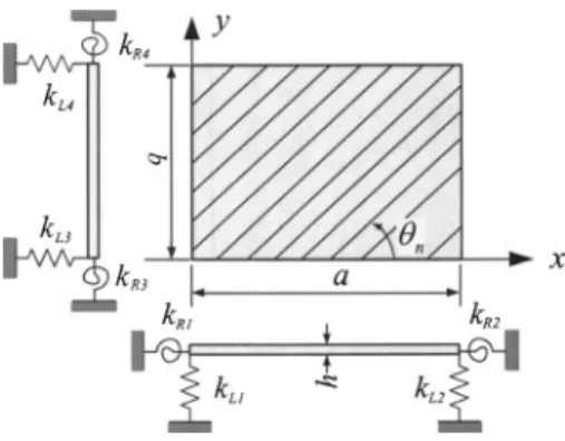
Consider a thin rectangular symmetrically laminated composite plate of length a0, width b0, and constant thickness h. The plate
composed of a finite number of orthotropic layers of the same material properties and thickness is partially supported by flexible restraints at the plate periphery as shown in Fig. 1. The x and y coordinates of the plate are taken in the midplane of the plate. The edge flexible supports of the elastically restrained plate can be modeled by longitudinal and torsional springs as shown in Fig. 2. It is noted that the effective length and width of the plate adopted in the vibration analysis are a and b, respectively. For free vibration, the plate vertical displacement w共x,y,t兲 is assumed to be of the form
w共x,y,t兲 = W共x,y兲sin t 共1兲
where W共x,y兲=deflection function; and =angular frequency. According to the classical lamination theory, the maximum strain energy UPand maximum kinetic energy T of the plate with the
neglect of rotary inertia effect are expressed, respectively, as 共Hung et al. 1993兲 UP= 1 2
冕
0 b冕
0 a冋
D11冉
2W x2冊
2 + 2D12冉
2W x2冊冉
2W y2冊
+ D22冉
2W y2冊
2 + 4D66冉
2W xy冊
2 + 4D16冉
2W x2冊冉
2W xy冊
+ 4D26冉
2W y2冊冉
2W xy冊
册
dx dy 共2兲 and T =1 2h 2冕
0 b冕
0 a W2dx dy 共3兲where Dij= bending stiffness coefficients; and=material density.
The bending stiffness coefficients are given by Dij=
冕
−h/2 h/2 Q ¯ ij 共m兲z2dz i, j = 1,2, 6 共4兲The transformed lamina stiffness coefficients Q¯ij共m兲 depending on the material properties and fiber orientation of the mth layer are expressed as Q¯11= Q11C4+ 2共Q12+ 2Q66兲C2S2+ Q22S4 Q¯12=共Q11+ Q22− 4Q66兲C2S2+ Q 12共C4+ S4兲 Q¯16=共Q11− Q12− 2Q66兲C3S +共Q12− Q22+ 2Q66兲CS3 Q¯22= Q11S4+ 2共Q12+ 2Q66兲C2S2+ Q22C4 Q¯26=共Q11− Q12− 2Q66兲CS3+共Q12− Q22+ 2Q66兲C3S Q¯66=共Q11+ Q22− 2Q12− 2Q66兲C2S2+ Q66共C4+ S4兲 Q¯12= Q¯21, Q¯16= Q¯61, Q¯26= Q¯62 共5兲 with Q11= E1 1 −1221; Q12= 12E2 1 −1221; Q22= E2 1 −1221 Q66= G12; C = cosm; S = sinm 共6兲
where E1, E2= Young’s moduli in the fiber and transverse
direc-tions, respectively; ij= Poisson’s ratio for transverse strain
in the j direction when stressed in the i direction; G12= shear
Fig. 1. Flexibly and partially supported laminated composite plate
Fig. 2. Model of elastically restrained laminated plate
modulus in the 1–2 plane; andm= lamina fiber angle of the mth
layer.
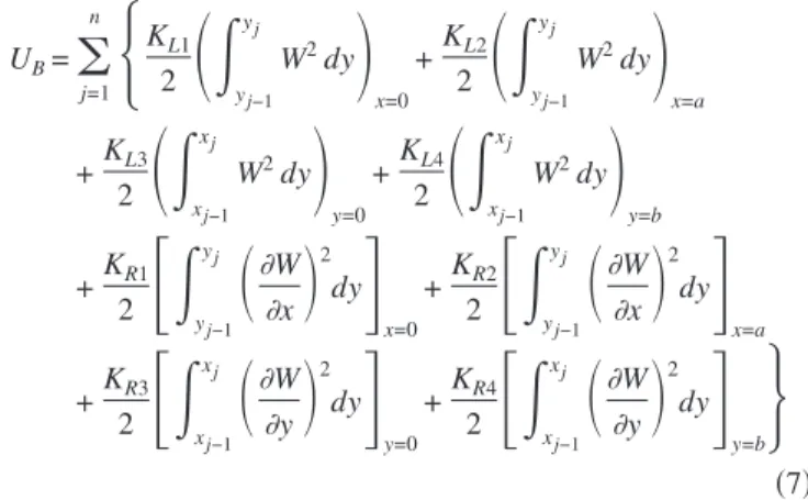
For the plate partially restrained by elastic edge supports, ad-ditional strain energy stored in the boundary springs exists. Herein, without loss of generality it is assumed that the plate is supported on the edges by 4n elastic restraints of which the n elastic restraints on each edge have same constant translational and rotational spring constants. The maximum total strain energy of the flexible restraints is thus written as
UB=
兺
j=1 n再
KL1 2冉
冕
y j−1 yj W2dy冊
x=0 +KL2 2冉
冕
y j−1 yj W2dy冊
x=a +KL3 2冉
冕
x j−1 xj W2dy冊
y=0 +KL4 2冉
冕
x j−1 xj W2dy冊
y=b +KR1 2冋
冕
y j−1 yj冉
W x冊
2 dy册
x=0 +KR2 2冋
冕
y j−1 yj冉
W x冊
2 dy册
x=a +KR3 2冋
冕
x j−1 xj冉
W y冊
2 dy册
y=0 +KR4 2冋
冕
x j−1 xj冉
W y冊
2 dy册
y=b冎
共7兲 where KLiand KRi共i=1, ... ,4兲=spring constants per unit lengthof the longitudinal and torsional springs on the ith edge, respec-tively; and xj, yj 共j=1, ... ,n兲=location coordinates of the ends
of the edge supports. The integrals in the above brackets are evaluated at the 4n edge supports of the plate. The total strain energy of the flexibly supported plate is then written as
U = UP+ UB 共8兲
Based on the Rayleigh–Ritz method, the deflection function can be expressed in the following nondimensional form
W共,兲 =
兺
i=1 I
兺
j=1J Ciji共兲j共兲 共9兲where Cij= undetermined displacement coefficients; i共兲,
j共兲=orthogonal functions; and ,=normalized coordinates.
Herein, the Legendre’s orthogonal polynomials are used in Eq.共9兲 to denoteiandj. For instance,i共兲 is written as
1共兲 = 1
2共兲 =
and for n艌3
n共兲 = 关共2n − 3兲 ⫻ n−1共兲 − 共n − 2兲 ⫻ n−2共兲兴/共n − 1兲
共10兲
where =共2x/a兲−1 with −1艋艋1; and =共2y/b兲−1 with
−1艋艋1. It is noted that the above orthogonal polynomials i共兲 satisfy the orthogonality condition
冕
−1 1 n共兲m共兲d =冦
0 if n⫽ m 2 2n − 1 if n = m冧
共11兲 Extremization of the functional⌸ which is defined as ⌸=U−T with respect to the displacement coefficients Cij leads to thefollowing eigenvalue problem:
共关K兴 − 2关M兴兲兵C其 = 0 共12a兲
with
K = KP+ KB 共12b兲
where 兵C其=displacement coefficients vector; K=structure stiff-ness matrix; KP= portion of structure stiffness matrix contributed
by plate stiffness; and KB= portion of structure stiffness matrix
contributed by the stiffnesses of edge restraints. The elements of
KP, KB, and M are expressed, respectively, as
关KP兴mnij= 16关D11Emi 22F nj 00/a4+ D 12共Emi 02F nj 20+ E mi 20F nj 02兲/共a2b2兲 + D22Emi00Fnj22/b4+ 2D16共E21miFnj01+ Emi12Fnj10兲/共a3b兲 + 2D26共Emi01Fnj21+ Emi10Fnj12兲/共ab3兲 + 4D 66Emi 11F nj 11/共a2b2兲兴 共13兲 关KB兴mnij= 2
兺
p=1 P 兵关KL1Jnj p m共− 1兲i共− 1兲 + KL2Jnj p m共1兲i共1兲兴/a +关KL3Imi p n共− 1兲j共− 1兲 + KL4Imi p n共1兲j共1兲兴/b其 + 8兺
p=1 P 兵关KR1Jnj p m ⬘共− 1兲i⬘共− 1兲 + KR2Jnj p m ⬘共1兲i⬘共1兲兴/a3 +关KR3Imipn⬘共− 1兲j⬘共− 1兲 + KR4Imipn⬘共1兲⬘j共1兲兴/b3其 共14兲 and 关M兴mnij=hEmi 00F nj 00 m,i = 1,2,3, . . . M,I; n, j = 1,2,3, . . . N,J; p = 1,2,3, . . . P 共15兲 with Emirs=冕
−1 1冋
drm共兲 dr dsi共兲 ds册
d; Fnjrs=冕
−1 1冋
dr n共兲 dr ds j共兲 ds册
d; r,s = 0,1,2 共16a兲 Imip =冕
p−1 p 关m共兲i共兲兴d; Jnj p =冕
p−1 p 关j共兲n共兲兴d 共16b兲 where p and p= normalized location coordinates of the endsof the edge supports. The above Rayleigh–Ritz method can be used to predict the natural frequencies of laminated composite plates partially supported by elastic restraints at the plate edges. The theoretically predicted natural frequencies will then be used for the parameters identification of the flexibly supported laminated composite plates as will be described in the following section.
System Identification
In this study, without loss of generality the elastic restraints under consideration are assumed to be made of strip-type pads with cross-sectional area be⫻heand Young’s modulus Eeas shown in
Fig. 3共a兲. The spring constants of the pad-type supports are deter-mined via the mechanics of materials approach. It is assumed that
the plate edges are perfectly bound to the top surfaces of the pads and the load per unit length acting on the top surface of the pad varies linearly across the width of the pad as show in Fig. 3共b兲. The distributed load per unit length on each pad can be replaced by two components, i.e., moment M and force P as shown in Fig. 3共c兲. It is further assumed that the plane surface of the pad remains plane after deformation. The vertical displacement ␦ induced by P alone is obtained as
␦ = Phe
Eebe
共17兲 Then the translational spring constant per unit length of the pad-type support derived from the above equation is
KL=
Eebe
he 共18兲
Similarly, the rotation induced by M alone is obtained as
= Mhe
1 12be3Ee
共19兲 Then the rotational spring constant per unit length of the pad-type support derived from the above equation is
KR=
Eebe
3
12he
共20兲 It is noted that for a plate with length a0and width b0restrained
by pad-like edge supports, the effective length a and width b of the plate become a0−共be/ 2兲 and b0−共be/ 2兲, respectively. Herein,
the problem of identification of system parameters共material and spring constants兲 of laminated composite plates partially re-strained by strip-type pads at the plate edges is formulated as a minimization problem. In mathematical form it is stated as
Minimize e共x兲 = 共*兲t共*兲
Subject to xiL艋 xi艋 xi
U i = 1 – 5 共21兲
where x =关E1, E2, G12,12, Ee兴=vector containing the design
vari-ables which presently are material constants of the plate and the Young’s modulus of the elastic restraints; *= n⫻1 vector
containing the differences between the measured and predicted values of the natural frequencies; e共x兲=error function measuring the sum of differences between the predicted and measured data; and xiL, xiU= lower and upper bounds of the material constants. The elements in*are expressed as
i
*=pi−mi
mi
i = 1 – 6 共22兲
wherepi,mi= predicted and measured values of the natural
fre-quencies, respectively. In general, the use of any conventional minimization technique to solve the identification problem of Eq. 共21兲 may encounter great difficulty in obtaining the global minimum. Herein, a multistart global minimization method together with an appropriate normalization technique for nor-malizing the design variables is adopted to solve the above system identification problem. In the proposed method, the above problem of Eq.共21兲 is first converted into an unconstrained mini-mization problem by creating the following general augmented Lagrangian共Vanderplaats 1984兲 ⌿¯ 共x˜,,,rp兲 = e共x˜兲 +
兺
j=1 5 共jzj+ rpzj 2+ jj+ rpj 2兲 共23兲 withFig. 3. Geometry and loading condition of pad-type support Fig. 4. Supporting condition of elastically restrained laminated
composite plates
zj= max
冋
gj共x˜j兲, −j 2rp册
gj共x˜j兲 = x˜j− x˜Uj 艋 0 j= max冋
Hj共x˜j兲, −j 2rp册
共24兲 Hj共x˜j兲 = x˜j L− x˜ j艋 0 j = 1 – 5where j,j,␥p= multipliers; and max关*, *兴 takes on the maxi-mum value of the numbers in the bracket. The modified design variables x˜ are defined as
x ˜ =
冉
E1 ␣1 ,E2 ␣2 ,G12 ␣3 ,12, Ee ␣4冊
共25兲 where ␣i= normalization factor. It is noted that the choice ofproper values of the normalization factors can produce appropri-ate search directions during the minimization process and thus help expedite the convergence of the solution. A detailed study has shown that the suitable values of x˜i共i=1, ... ,5兲 are greater than 0 and less than 10. Furthermore, it is worth pointing out that the original design variables are used in the Rayleigh–Ritz method to compute the theoretical natural frequencies for deter-mining the error function in Eq.共23兲. The update formulas for the multipliersj,j, and␥pare
j n+1= j n+ 2r p nz j n n+1j =jn+ 2rpnnj j = 1 – 5 rp n+1 =
再
␥0rp n if r p n+1⬍ r p max rpmax if rn+1p 艌 rpmax冎
共26兲 where the superscript n denotes iteration number; ␥0= constant;and rpmax= maximum value of rp. The parameters
j 0, j 0, r p 0,␥ 0, rp
maxare chosen as
j 0= 1.0 j 0= 1.0 r p 0= 0.4 ␥0= 2.5 rp max = 100 共27兲
The constrained minimization problem of Eq. 共21兲 has thus become the solution of the following unconstrained optimization problem:
Minimize
⌿¯ 共x˜,,,rp兲 共28兲
The above unconstrained optimization problem is to be solved using a multistart global optimization algorithm. In the adopted optimization algorithm, the objective function is treated as the potential energy of a traveling particle and the search trajectories
Table 1. Experimental Natural Frequencies of Composite Plates
Layup Geometry
Support condition
Natural frequency number
1 2 3 4 5 6 Mean COV 共%兲 Mean COV 共%兲 Mean COV 共%兲 Mean COV 共%兲 Mean COV 共%兲 Mean COV 共%兲 关0°/90°/0°兴2S Square A 154 0.3 361 0.47 436 0.36 611 0.14 660 0.21 765 0.16 B 161 0.0 373 0.25 476 0.14 578 0.34 702 0.16 720 0.63 关45°/−45°/45°兴2S Square A 177 0.45 378 0.44 435 0.42 596 0.23 655 0.37 818 0.07 B 178 0.24 404 0.21 451 0.27 668 0.23 716 0.29 787 0.16 关0°兴12 Square A 152 0.44 241 0.3 386 0.3 416 0.54 601 0.25 616 0.36 B 158 0.34 244 0.32 405 0.0 535 0.2 561 0.14 600 0.21 关0°/90°/0°兴2S Rectangle C 110 0.0 245 0.22 327 0.16 435 0.18 467 0.28 606 0.15 关45°/−45°/45°兴2S Rectangle C 253 0.39 347 0.15 394 0.23 514 0.41 578 0.27 253 0.22
Note: COV⫽Coefficient of variation.
Fig. 5. Experimental setup for impulse vibration testing
Fig. 6. Frequency response spectrum of 关0°/90°/0°兴2S plate with
A-type supporting condition
for locating the global minimum are derived from the equation of motion of the particle in a conservative force field 共Snyman and Fatti 1987兲. The design variables, i.e., the plate elastic constants and Young’s modulus of the elastic restraints, which make the potential energy of the particle, i.e., the objective function, the global minimum constitutes the solution to the problem. In the minimization process, a series of starting points for the design variables of Eq.共25兲 are selected at random from the region of interest. The lowest local minimum along the search trajectory initiated from each starting point is determined and recorded. A Bayesian argument is then used to establish the probability of the current overall minimum value of the objective function being the global minimum, given the number of starts and the number of times this value has been achieved. The multistart optimization procedure is terminated when a target probability, typically 0.99, has been exceeded.
Experimental Investigation
In the experimental study, a number of laminated composite plates with different layups were fabricated using T300/2500 graphite/epoxy prepreg tapes produced by Torayca Co., Japan.
The dimensions 共a0⫻b0⫻h兲 of the laminated composite plates were either 22⫻22⫻0.15 cm3 or 32⫻22⫻0.15 cm3. The
aver-age and coefficient of variation共COV兲 of the mass density of the plates were 1,548 kg/ m3 and 1.22%, respectively. The elastic
constants of the graphite/epoxy composite material were first de-termined experimentally using the standard specimens in accor-dance with the revelant ASTM specifications 共ASTM 1990兲. In the material testing, each elastic constant was determined using three specimens. The means and COVs of the elastic constants obtained from the tests are as follows:
E1= 146.503 GPa共0.72%兲, E2= 9.223 GPa共1.19%兲
G12= 6.836 GPa共3.16%兲, 12= 0.306共0.19%兲 共29兲
The values in the parentheses in the above equation denote the COVs of the elastic constants of the composite material. Strip-type pads made of foam plastic materials were used to support the laminated composite plates. The elastic constant Eeof the flexible
pads was also determined following the standard ASTM tensile testing procedure. The mean and COV of Eeare 2.028 MPa and
2.3%, respectively. The cross-sectional dimensions of the pads were be= 0.5 cm and he= 2.1 mm.
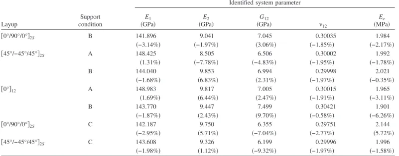
Table 2. Actual Natural Frequencies of Graphite/Exoxy关0°/90°/0°兴2SPlate Supported by Elastic Pads共A Type兲 with Different Rigidities
Young’s modulus of elastic pad 共MPa兲
Spring constant Natural frequency number
KL 共kN/m2兲 KR 共N兲 1 2 3 4 5 6 1.0 2.38095 4.96032 151.3163 340.3899 391.3919 575.7812 592.2373 653.2147 15.0 35.7143 74.40476 170.972 394.3665 499.4967 663.1584 786.6243 990.3991
Table 3. Identified System Parameters of Graphite/Epoxy关0°/90°/0°兴2SPlate Supported by Elastic Pads共A Type兲 with Ee= 1.0 MPa Using Actual Natural
Frequencies. Starting point number Stage System parameter Number of iterations E1
共GPa兲 共GPa兲E2 共GPa兲G12 12
Ee 共MPa兲 1 Initial 194.538 0.849 16.519 0.21825 4.433 12 Final 146.5032 9.2231 6.836 0.306 1 2 Initial 224.703 17.862 0.225 0.41863 13.719 10 Final 87.7715 3.3359 3.0379 0.4682 19.7024 3 Initial 234.44 22.888 16.971 0.19005 4.258 12 Final 146.503 9.2232 6.836 0.306 1.0 4 Initial 251.766 22.601 7.614 0.10768 14.206 11 Final 146.503 9.223 6.836 0.306 1.0 5 Initial 165.37 17.196 3.731 0.09233 10.058 7 Final 87.7696 3.3364 3.0385 0.4682 19.7025 6 Initial 163.239 35.29 16.643 0.01602 7.718 11 Final 146.5037 9.2218 6.8358 0.3061 1.0 7 Initial 62.819 20.423 7.079 0.26991 12.009 7 Final 87.7599 3.3384 3.0404 0.4682 19.7024 8 Initial 52.512 17.035 17.208 0.02261 17.514 9 Final 87.7607 3.3382 3.0403 0.4682 19.7024 9 Initial 196.172 25.595 11.252 0.01915 13.345 10 Final 146.5032 9.2231 6.836 0.306 1.0 Global 146.503 9.223 6.836 0.306 1.0 Probability minimum 共0%兲 共0%兲 共0%兲 共0%兲 共0%兲 0.9923
Note: Values in the parentheses denote percentage difference between identified and actual data.
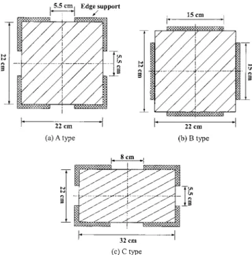
The laminated composite plates partially supported by the flexible strip-type pads at the plate edges were subjected to im-pulse vibration testing. The supporting conditions of the compos-ite plates are shown in Fig. 4 in which A- and B-type supporting conditions are for the square 共22⫻22⫻0.15 cm3兲 composite
plates while the C-type supporting condition is for the rectangular 共32⫻22⫻0.15 cm3兲 composite plates. In the vibration testing of
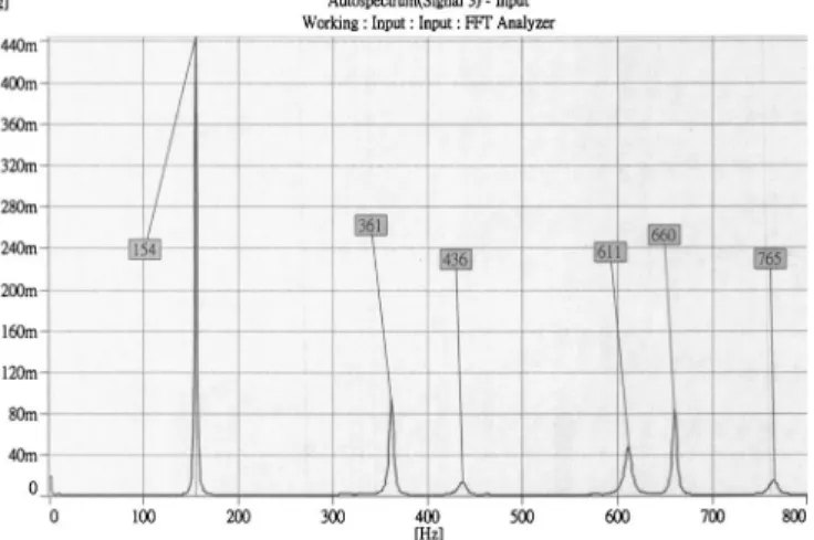
the flexibly supported composite plate, a hand held impulse ham-mer 共Kistler 9722A500, Kistler Instrument, United States兲 was used to excite the composite plate at different points on the plate, a force transducer 共Kistler 9904A, Kistler Instrument, United States兲 attached to the hammer’s head to measure the input forces, an accelerometer of mass 0.14g 共AP19, APTechnology, The Netherlands兲 to pick up the vibration response data at differ-ent locations on the plate, and a data acquisition and analysis system 共B&K 3560C and B&K Pulse Labshop, Version 6.1兲 to process the vibration data from which the natural frequencies of the composite plates were extracted. The experimental setup for the impulse vibration testing of the plates is shown in Fig. 5. It is noted that each flexibly supported composite plate was then tested 15 times. Each time when the plate was tested a set of vibration data was produced for constructing the frequency response spectrum of the plate from which the first six natural frequencies of the plate were extracted. Without loss of generality, it was assumed that the small modal damping ratios with values less than 2% had negligible effects on the first six natural fre-quencies of the plates. Therefore, in determining the natural frequencies from the frequency response spectra, the frequencies associated with the peak responses were treated as the natural frequencies of the plates. For illustration purposes, Fig. 6 shows a typical frequency response spectrum of the square关0°/90°/0°兴2S plate with A-type supporting conditions. It is noted that the first six natural frequencies of the plate can be easily identified from the frequency response spectrum as shown in the figure. The
means and COVs of the first six measured natural frequencies of the elastically restrained laminated composite plates with dif-ferent layups and supporting conditions determined from the impulse vibration testing of the plates are listed in Table 1. It is noted that the COVs of the natural frequencies obtained from the tests are less than 0.45%. The means of the measured natural frequencies of the plates are to be used in the following identifi-cation of the plate parameters.
Results and Discussion
Before proceeding to the system identification of the elastically restrained laminated composite plates that have been tested, a number of numerical examples are first given to illustrate the capability of the proposed method in identifying the elastic con-stants of plates made of different laminated composite materials and partially supported by elastic pads with different rigidities. The first example is the system identification of the square 关0°/90°/0°兴2S plate with A-type supporting condition shown in
Fig. 4. The关0°/90°/0°兴2Splate is made of graphite/epoxy
com-posite material with the actual elastic constants just as the means given in Eq. 共29兲. The actual natural frequencies of the 关0°/90°/0°兴2S plate supported by elastic pads with different
Young’s moduli are computed and tabulated in Table 2. The ac-tual natural frequencies of the plate are then treated as “mea-sured” natural frequencies in the system parameters identification process. The upper and lower bounds of the system parameters are chosen based on experience
0艋 E1艋 400 GPa; 0 艋 E2艋 40 GPa; 0 艋 G12艋 20 GPa
0艋 12艋 0.5; 0 艋 Ee艋 20 MPa 共30兲
The modified design variables of Eq.共25兲 are obtained via the use of the following normalization factors:
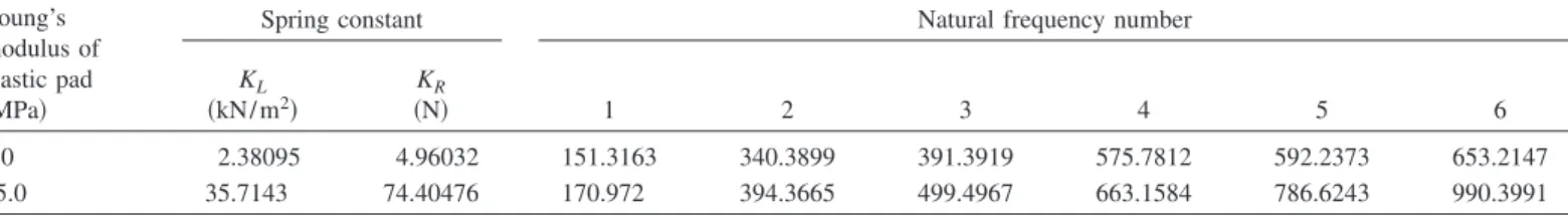
Table 4. Identified System Parameters of Graphite/Epoxy 关0°/90°/0°兴2S Plate Supported by Elastic Pads共A Type兲 with Ee= 15.0 MPa Using Actual
Natural Frequencies Starting point number Stage System parameter Number of iterations E1
共GPa兲 共GPa兲E2 共GPa兲G12 12
Ee 共MPa兲 1 Initial 194.551 21.895 16.967 0.13555 7.055 12 Final 146.5032 9.2231 6.8361 0.306 15.0 2 Initial 175.037 25.389 14.534 0.27722 8.494 12 Final 146.5034 9.2231 6.8364 0.3059 15.0 3 Initial 48.043 25.994 3.448 0.25919 8.535 13 Final 146.503 9.223 6.836 0.306 15.0 4 Initial 299.286 9.985 8.23 0.37452 19.554 10 Final 146.503 9.223 6.836 0.306 15.0 Global 146.503 9.223 6.836 0.306 15.0 0.9921 minimum 共0%兲 共0%兲 共0%兲 共0%兲 共0%兲
Note: Values in the parentheses denote percentage difference between identified and actual data.
Table 5. Actual Natural Frequencies of Glass/Epoxy关0°/90°/0°兴2SPlate Supported by Elastic Pads共A Type兲 with Different Rigidities
Young’s modulus of elastic pad 共MPa兲
Spring constant Natural frequency number
KL 共kN/m2兲 KR 共N兲 1 2 3 4 5 6 1.0 2.38095 4.96032 87.91181 208.9391 235.5438 344.3321 384.733 428.8373 15.0 35.7143 74.40476 101.7888 236.4288 272.623 382.7989 466.449 557.0408
␣1= 100 共31a兲
and
␣i= 10 i = 2 – 4 共31b兲
In view of Eqs. 共30兲 and 共31兲, the feasible intervals of the modified design variables are thus obtained as关0, 4兴, 关0, 4兴, 关0, 2兴, 关0, 0.5兴, and 关0, 2兴 for E1, E2, G12,12, and Ee, respectively. Since
the modified design variables are less than 10, the search for the solution can be expedited. For the case where the elastic pads have Ee= 1.0 MPa, nine starting points are randomly generated
and for each starting point around 7–12 iterations are required to locate the lowest local minimum. The starting points, the lowest local minima for the starting points, numbers of iterations re-quired to obtain the lowest local minima, and the global minimum are listed in Table 3. It is noted that the actual system parameters have been identified with probability greater than 0.99. Similarly, for the case where the elastic pads have Ee= 15 MPa, the results
are listed in Table 4. Again it is noted that the actual system parameters have also been identified in an efficient and effective way where only four starting points have been randomly gener-ated and around 12 iterations required to locate the lowest local minima for the starting points. Next consider the system identifi-cation of the square 关0°/90°/0°兴2S plate with same supporting
condition but made of glass/epoxy composite material of which the properties are as follows:
E1= 43.5 GPa, E2= 11.5 GPa, G12= 3.45 GPa,
共32兲 12= 0.27, = 2,000 kg/m3
The actual natural frequencies of the glass/epoxy 关0°/90°/0°兴2S plate supported by the elastic pads with different Young’s moduli are computed and listed in Table 5. The actual natural frequencies treated as the “measured” ones together with the bounds in Eq. 共30兲 and normalization factors in Eqs. 共31兲 are used in the present method to identify the system parameters of the glass/ epoxy plate supported by the elastic pads with different rigidities. The estimates of the system parameters together with the numbers of starting points and the average numbers of iterations required to obtain the global minima for the cases under consideration are listed in Table 6. It is noted that the present method is also able to produce the actual system parameters in an efficient and effective way for the flexibly supported glass/epoxy关0°/90°/0°兴2Splate.
Now the present method is applied to the system identification of the elastically restrained laminated composite plates which have been tested. The measured natural frequencies of the 关0°/90°/0°兴2Splate with A-type supporting conditions in Table 1
are used as an example to illustrate the system identification pro-cess of the present method. Table 7 lists the randomly generated starting points, the lowest local minima obtained for the starting points, the numbers of iterations required for getting the lowest local minima, and the global minimum. It is noted that only six starting points are needed to obtain the global minimum with
Table 6. Identified System Parameters of Glass/Epoxy关0°/90°/0°兴2SPlate Supported by Elastic Pads共A Type兲 with Different Rigidities Using Actual
Natural Frequencies Case Actual Ee 共MPa兲 Number of starting points Average number of iteration System parameter E1
共GPa兲 共GPa兲E2 共GPa兲G12 12
Ee
共MPa兲
1 1.0 7 8 43.5共0%兲 11.5共0%兲 3.45共0%兲 0.27共0%兲 1.0共0%兲
2 15.0 8 10 43.5共0%兲 11.5共0%兲 3.45共0%兲 0.27共0%兲 15.0共0%兲
Note: Values in the parentheses denote percentage difference between identified and actual data.
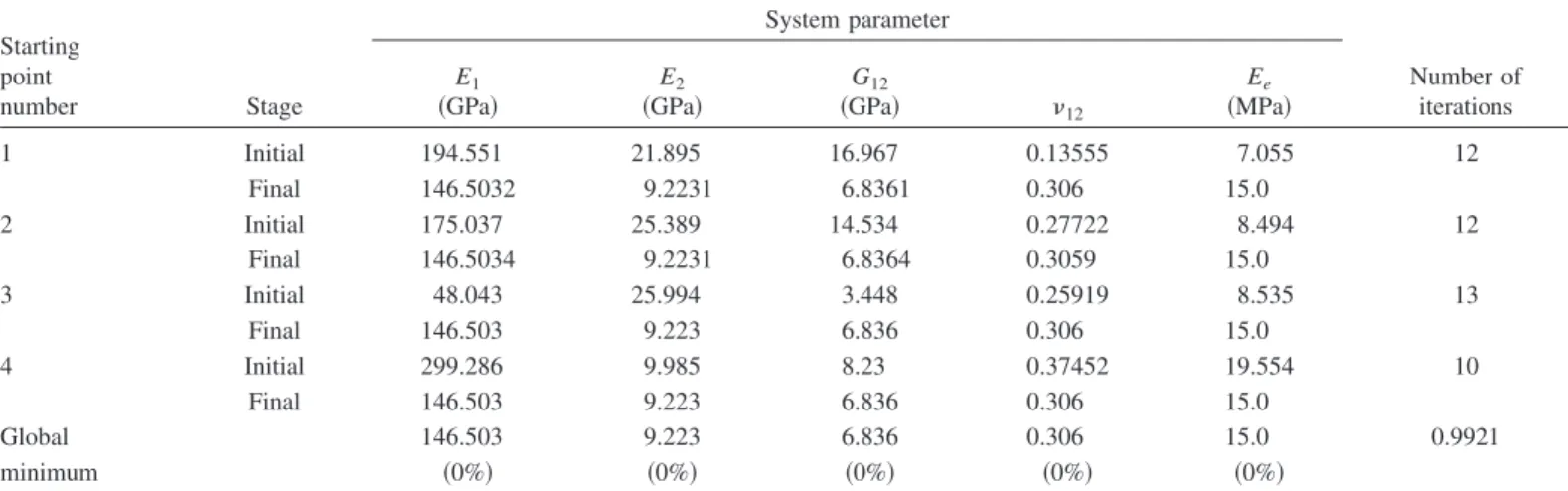
Table 7. System Identification of Square关0°/90°/0°兴2SPlate with A-Type Supporting Condition Using Experimental Natural Frequencies
Starting point number Stage System parameter Number of iterations E1
共GPa兲 共GPa兲E2 共GPa兲G12 12
Ee 共MPa兲 1 Initial 44.645 34.586 4.881 0.42941 5.985 8 Final 141.164 8.982 6.982 0.30002 2.211 2 Initial 160.933 0.683 17.640 0.37422 3.853 8 Final 141.162 8.982 6.983 0.30001 2.211 3 Initial 238.425 0.880 19.186 0.03901 4.472 11 Final 141.158 8.983 6.984 0.30001 2.211 4 Initial 55.035 16.731 17.782 0.03920 16.305 10 Final 109.693 5.521 3.529 0.30015 18.005 5 Initial 51.864 7.121 0.005 0.17907 6.870 10 Final 141.167 8.981 6.982 0.30001 2.211 6 Initial 213.219 36.831 9.558 0.33293 1.689 5 Final 141.171 8.980 6.981 0.30002 2.211 Global minimum 141.167 8.981 6.982 0.30001 2.211 Probability 共−3.64%兲 共−2.62%兲 共2.14%兲 共−1.96%兲 共9.02%兲 0.9959
Note: Values in the parentheses denote percentage difference between identified and actual data.
probability exceeding 0.99, the numbers of iterations for getting the lowest local minima are less than or equal to 11, and the percentage differences between the actual and identified system parameters are less than or equal to 9.02%. In a similar way, the system parameters of the other flexibly supported laminated composite plates that have been tested can also be identified using the measured natural frequencies listed in Table 1. The identified system parameters and their associated percentage errors for the tested plates are listed in Table 8. Again, it is noted that very good estimates of the system parameters with percentage differences less than or equal to 9.7% have also been obtained for the plates. It is also noted that for all the tested plates, better estimates of E1
and12of which the percentage differences are less than or equal
to 3.64% can be obtained. It is worth pointing out that the dif-ferences between the identified and actual system parameters of the plates that have been tested in this study may be due to im-proper modeling of the flexibly supported plates and existence of noise in the measurement data. Regarding the modeling of the elastic edge pads, the mechanics of materials approach adopted to calculate the spring constants of the edge supports might be over-simplified in simulating the actual behaviors of the edge supports. Therefore, a more sophisticated method such as the finite element method may be needed to model the elastic edge supports if more accurate results are desired. On the other hand, the effects of measurement noise on the identified system parameters and the sources of the noise should be studied in detail so that the mea-surement noise incurred in the vibration testing of the plates can be suppressed or the detrimental effects of the measurement noise can be minimized or even eliminated.
Conclusions
A nondestructive evaluation method for system identification of laminated composite plates partially supported by elastic pad-like restraints using six experimentally measured natural frequencies of the plates have been presented. The system identification pro-cess in the proposed method has included the utilization of the Rayleigh–Ritz method for predicting the theoretical natural fre-quencies of the elastically restrained laminated composite plates
using trial values of the system parameters, the construction of the error function that measures the sum of the differences between the experimental and theoretical predictions of the system natural frequencies, the use of a multistart global minimization method to identify the elastic constants by making the error function a glo-bal minimum, and a design variables normalization technique for expediting the convergence of the search of the global minimum. Both numerical and experimental investigations have been con-ducted to demonstrate the capability, effectiveness, accuracy, and applications of the proposed method. In the numerical study, it has been shown that the proposed method can identify the ac-tual system parameters of partially and elastically restrained plates made of different laminated composite materials in an efficient and effective way. In the experimental investigation, sev-eral flexibly restrained laminated composite plates with different layups and supporting conditions have been subjected to impulse testing and the first six natural frequencies of the plates have been measured. The uses of the measured natural frequencies in the proposed method have also produced very good estimates of the system parameters for the laminated composite plates with per-centage differences less than or equal to 3.64% for E1, 7.78% for E2, 9.70% for G12, 2.77% for12, and 9.02% for Ee.
Acknowledgment
This research work was supported by the National Science Council of the Republic of China under Grant No. NSC 93-2218-E-009-014. Their support is gratefully appreciated.
References
ASTM.共1990兲. Standards and literature references for composite
mate-rials, 2nd Ed., West Conshohocken, Pa.
Berman, A., and Nagy, E. J.共1983兲. “Improvement of a large analytical model using test data.” AIAA J., 21, 1168–1173.
Castagnède, B., Jenkins, J. T., Sachse, W., and Baste, S.共1990兲. “Optimal determination of the elastic constants of composite materials from ultrasonic wave-speed measurements.” J. Appl. Phys., 67,
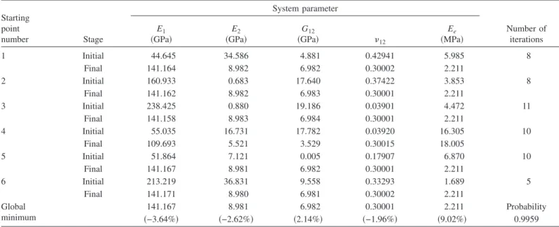
Table 8. Identified System Parameters of Plates Subjected to Impulse Vibration Testing
Layup
Support condition
Identified system parameter
E1
共GPa兲 共GPa兲E2 共GPa兲G12 12
Ee 共MPa兲 关0°/90°/0°兴2S B 141.896 9.041 7.045 0.30035 1.984 共−3.14%兲 共−1.97%兲 共3.06%兲 共−1.85%兲 共−2.17%兲 关45°/−45°/45°兴2S A 148.425 8.505 6.506 0.30002 1.992 共1.31%兲 共−7.78%兲 共−4.83%兲 共−1.95%兲 共−1.78%兲 B 144.040 9.853 6.994 0.29998 2.021 共−1.68%兲 共6.83%兲 共2.31%兲 共−1.97%兲 共−0.35%兲 关0°兴12 A 148.983 9.817 7.005 0.30015 1.965 共1.69%兲 共6.44%兲 共2.47%兲 共−1.91%兲 共−3.11%兲 B 143.770 9.447 7.499 0.30421 1.901 共−1.87%兲 共2.43%兲 共9.70%兲 共−0.58%兲 共−6.26%兲 关0°/90°/0°兴2S C 142.187 9.750 6.355 0.29751 2.144 共−2.95%兲 共5.71%兲 共−7.04%兲 共−2.77%兲 共5.72%兲 关45°/−45°/45°兴2S C 143.608 9.326 6.199 0.29996 1.996 共−1.98%兲 共1.12%兲 共−9.32%兲 共−1.97%兲 共−1.58%兲
Note: Values in parentheses denote percentage difference between predicted and measured data.
2753–2761.
Deobald, L. R., and Gibson, R. F. 共1988兲. “Determination of elastic constants of orthotropic plates by a modal analysis/Rayleigh-Ritz technique.” J. Sound Vib., 124共2兲, 269–283.
Fallstrom, K. E., and Jonsson, M.共1991兲. “A nondestructive method to determine material properties in anisotropic plate.” Polym. Compos.,
12共5兲, 293–305.
Hung, K. C., Lim, M. K., and Liew, K. M. 共1993兲. “Boundary beam characteristics orthonormal polynomials in energy approach for vibra-tion of symmetric laminates. II: Elastically restrained boundaries.”
Compos. Struct., 26, 185–209.
Kam, T. Y., and Lee, T. Y. 共1994兲. “Crack size identification using an expanded mode method.” Int. J. Solids Struct., 31, 925–940. Kam, T. Y., and Liu, C. K.共1998兲. “Stiffness identification of laminated
composite shafts.” Int. J. Mech. Sci., 40共9兲, 927–936.
Lubin, G. 共1982兲. Handbook of composites, van Nostrand Reinhold, London.
Moussu, F., and Nivoit, M.共1993兲. “Determination of elastic constants of orthotropic plates by a modal analysis/method of superposition.”
J. Sound Vib., 165共1兲, 149–163.
Nielsen, S. A., and Toftegaard, H. 共1998兲. “Ultrasonic measurement of elastic constants in fiber-reinforced polymer composites under influ-ence of absorbed moisture.” Int. J. Ultrasonic, 38, 242–246. Qian, G. L., Hoa, S. V., and Xiao, X.共1997兲. “A vibration method for
measuring mechanical properties of composite, theory and experi-ment.” Compos. Struct., 39共1–2兲, 31–38.
Schwartz, M. M.共1983兲. Composite materials handbook, McGraw-Hill, New York.
Snyman, J. A., and Fatti, L. P.共1987兲. “A multi-start global minimization algorithm with dynamic search trajectories.” J. Optim. Theory Appl.,
54共1兲, 121–141.
Sol, H., Hua, J., Visscher, J., Vantomme, J., and Wilde, W. P.共1997兲. “A mixed numerical/experimental technique for the nondestructive identification of the stiffness properties of fibre reinforced composite materials.” NDT & E Int., 30共2兲, 85–91.
Vanderplaats, G. N.共1984兲. Numerical optimization techniques for
engi-neering design with applications, McGraw–Hill, New York.
Wang, W. T., and Kam, T. Y. 共2000兲. “Material characterization of laminated composite plates via static testing.” Compos. Struct., 50共4兲, 347–352.