齒輪式機器人機構之系統化設計(III)
計劃編號:NSC89-E-002-021 執行期間:八十八年八月一日至八十九年七月三十一日 主持人:陳達仁,國立台灣大學教授 計畫參與人員:彭勁堯、劉佳斌、白維銘 摘要 此計劃之目的在於將關節式齒輪機構(AGM)的 圖畫表示法在電腦輔助描繪程式的環境下,轉換為 功能表示法。為達此目的,必須設計關節式齒輪機 構的幾何構形資料格式,並發展上述轉換之規則。 模組化的概念可被應用於關節式齒輪機構之幾何 構形的資料格式設計。在此設計概念下,關節式齒 輪機構的幾何構形資料被分為多個傳動線(MTL) 階層的子模組,而傳動線階層模組又可細分為單元 (Unit)階層模組的集合。 在此計劃所提出的描繪方法中,關節式齒輪機構 的功能表示法是由齒輪對(gear pair)、臂桿(car-rier) 、 軸 (hub) 、地桿 (ground) 以 及作動器 (end-effector)等各種繪圖元件(sketching component) 所組成。為了簡化各個繪圖元件空間安排的過程, 元件組(component group)將多個有關連的齒輪 對、臂桿和軸組合起來,成為一體的安排組合。單 元階層繪圖模組可視為由一個或多個的元件組所 構成。經由搜尋元件組的過程,單元階層模組可由 圖畫表示法轉換為功能表示法。在此過程中,一並 建立單元階層模組的幾何構形資料庫以供關節式 齒輪機構之設計使用。一個自由度為 3 的關節式 齒輪機構之電腦輔助描繪過程列於本文之末。 ABSTRACTThe objective of this research is to reverse-transform the graph representation of the articu-lated gear mechanism (AGM) into its functional representation, which can be visualized by the sketching program developed by the author. Ahead of the making of the rules for the reverse-transformation, the AGM’s geometrical data for-mat, which can be manipulated and stored by computer, is designed under the concept of modular design. Under this design concept, the geometrical data of the AGM is divided into me-chanical-transmission-line-level (MTL-level) modules, and the MTL-level modules are subdi-vided into unit-level sketching modules, which include input and transmission units (IU and TU). In the proposed sketching methodilogy, the elements that comprise the whole functional representations of sketching modules are called sketching components. They are gear pair, car-rier, hub, ground, and end-effector. The layout parameters are chosen to define the geometry of each of them. For the simplicity of the layout arrangement, a data group, called component group, is created to group gear pairs, carriers,
and hubs together. It is shown that the functional representation of the unit-level sketching module is composed of several component groups.
By searching component groups in unit-level-modules, the reverse-transformations of the unit-level modules are performed, and the geometrical database is established during the process. With the database for the unit-level sketching modules, the AGM design procedure is just to select desired modules in the database to form the entire functional representation of the AGM. The design procedure of a 3-dof AGM is illustrated and explained at the end of this article. 1. Introduction
The major breakthrough in the design of ar-ticulated gear mechanism (AGM) is the intro-ducing of the graph theory. By using the graph to represent the topology of AGM, the analysis is transformed to an abstract level within which the structural characteristics of AGM are found. Based on the identified topological characteris-tics, the AGM with desired specification can be enumerated systematically. The design proce-dure, however, is not completed unless the enu-merated graphs of AGM are reverse-transformed into their functional representations. The auto-matic sketching is dealing with the issue of the reverse-transformation of mechanism. With the algorithm for the reverse-transformation, the automatic sketching program visualizes the de-sired mechanism onto the computer monitor.
In the recent years, considerable efforts have been made for the enumeration of AGM. Chang and Tsai (1990) introduced the concept of mechanical transmission line (MTL) to describe the relations between joint and input torques, and admissible structure matrices were searched to describe the mechanical couplings of the mechanism. Chen and Shiue (1996) demon-strated that a MTL can be decomposed into an input unit (IU) and several transmission units (TUs), which are identified from the atlas of non-fractionated GKCs (Freudenstein, 1971; Tsai, 1987; Ravisankar and Mruthyunjaya, 1985; Kim and Kwak, 1990; Tsai and Lin, 1989; Hsu, 1992). With the atlas of admissible units, MTLs of de-sired number of links are enumerated. By as-signing the number of links of an AGM, suitable MTLs are selected from the enumerated atlas to construct mechanisms with a desired form of structure matrix. Based on the atlas of input and
transmission units, which are enumerated by Chen and Shiue (1996), Chen and Liu (1998) presented the composition polynomial that can be constructed to symbolically represent all pos-sible structural compositions of the desired AGM. From the composition polynomial and an atlas of units, admissible AGMs are efficiently enumer-ated.
In contrast to the research devoted to the to-pological enumeration, the research on reverse-transformation, which transforms the graph rep-resentation of an AGM into its functional repre-sentation, has rarely been done in the area of automatic sketching. On the other hand, the subject of reverse transformations for some other mechanisms has been discussed in several pa-pers. Olson, Thompson, Riley, and Erdman (1985) presented an algorithm to transform the graph into its line graph, which is a form of kine-matic chain. Chieng and Hoeltzel (1990) did the research about the automatic sketching for planar kinematic chains and epicyclic gear trains. Chatterjee and Tsai (1995) proposed a method to sketch the epicyclic gear mechanism from its graph, and developed a c-language-based pro-gram to sketch epicyclic gear mechanisms.
On the basis of knowledge about AGM devel-oped previously, this article presents a method-ology by which the functional representations of IU and TU can be reverse-transformed from their graph representations. By constructing the geometrical database for IU and TU, the AGM design process can be simplified to just select desired IUs and TUs from the established data-base. With the computer-aided sketching pro-gram developed by the author, an AGM can be synthesized topologically and sketched onto a computer monitor.
2. Structural Characterictics of AGM
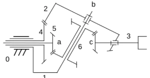
The functional representation of a 3-dof wrist-type AGM is shown in Fig. 1. In the AGM, link 0 is the ground, links 1, 4 and 5 are the input links, and link 3 is the output link, called the end-effector. The AGM has three revolute axes, and they are labeled as a, b, and c respectively.
0 1 2 3 4 5 6 a b c
Fig. 1 Functional represenation of an AGM In the graph representation of a gear mecha-nism, links are represented by vertices, revolute joints by thin edges, gear pairs by heavy edges,
and thin edges are labeled according to their axes locations. Tsai (1988) showed that a can-onical graph can be uniquely defined by re-arranging the coaxial links. In the canonical graph, there are no repeated axis labels in any thin-edged path originated from the base link, which is the ground of the mechanism. The can-onical graph of the AGM sketched in Fig. 1 is shown in Fig. 2. b 0 a 1 2 a 3 b c a 4 5 6
Fig. 2 Canonical Graph of an AGM Among all thin-edged paths, the path, which starts from the ground link 0 and ends at the end-effector link 3, is called the equivalent-open-loop-chain (EOLC). Each link of the EOLC is referred to as a primary link while all the other links of the AGM are called secondary links. The joints or axes that are located between adjacent primary links are called primary joints or axes. The relative angular displacement between any two adjacent primary links is referred to as a joint angle, and the resultant torque exerted on this joint is called the joint torque. Chang and Tsai (1990) showed that an AGM can be decomposed into several mechanical transmission lines (MTLs) which describe how the resultant joint torques are affected by the input actuator torques. The three MTLs decomposed from the canonical graph shown in Fig. 2 is shown in Fig. 3.The torque vector
τ
at joint space and the input tor-que vectorξ
at actuator space are related by:ξ
=
τ
A
(1)In Eq. (1), A is the structure matrix, and the ele-ments of A are functions of gear ratios. Chang and Tsai (1990) also showed that each column of the structure matrix represents a MTL, and it describes where the input actuator is located and how the input torque are transmitted to various joints of the EOLC.
b 0 a 1 2 a 3 b c 5 6 0 a 1 b 0 a 1 2 a 4 b 2 c 3 6 0 a 1 b 1 2 a 4 0 a 5 1 a b 5 6 0 a 4 Fig. 3 Three MTLs
Chen and Shiue (1998) showed that, by re-arranging the coaxial links, a MTL can be
de-composed into an input unit (IU) and several transmission units (TUs). The re-arranged pseudo-isomorphic graphs of the MTLs are shown in Fig. 3. In the figure, each unit has one primary link and is connected to its adjacent unit by sharing a common secondary link called the connecting link. Note that the joint between a connecting link and the primary link of a unit is coaxial with that of its associated adjacent unit.
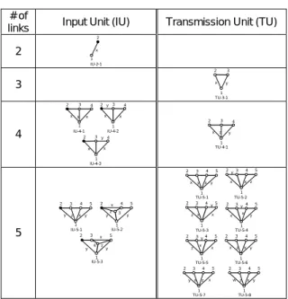
In addition to the decomposition scheme, Chen and Shiue (1998) also developed a methodology for the synthesis of AGM basing on the charac-teristics identified in the decomposition process. In their approach, an n-dof AGM with an n-by-n desired structure matrix is synthesized by com-bining n MTLs. Each MTL has at least one input unit as the first element and several transmission units connected in series with the input unit. The IU and TU(s), which compose the MTL, are se-lected form the atlas shown in Table 1.
Table 1 Admissible IU and TU # of
links Input Unit (IU) Transmission Unit (TU) 2 1 x 2 IU-2-1 3 1 x y 2 3 TU-3-1 4 1 xy 2 3 x 4 IU-4-1 2 x y 1 3 x 4 IU-4-2 IU-4-3 2 x y 1 3 x 4 1 x y 2 3 z 4 TU-4-1 5 1 y z 2 3 x 4 5 y IU-5-1 2 y z 5 3 x 4 1 y IU-5-2 y z 5 3 x 4 1 y IU-5-3 2 1 x y 2 3 x 4 5 y TU-5-1 1 x y 2 3 x 4 5 z TU-5-2 1 TU-5-3 x y 2 3 x 4 5 z 3 x y 1 2 x 4 5 z TU-5-4 3 x y 1 2 x 4 5 z TU-5-5 1 x z 2 3 x 4 5 y TU-5-6 1 x z 2 3 x 4 5 y TU-5-7 1 wz 2 3 x 4 5 y TU-5-8
3. Computer-aided Sketching Methodology The structural tree representation of AGM is illustrated in Fig. 4. In the figure, an n-dof AGM is composed of n MTLs and an n-joint EOLC, where the MTLs are the combinations of IUs and TUs. Thus the AGM-level geometrical data can be divided into MTL-level and unit-level sub-systems, which compose the entire AGM.
n-dof AGM MTL 1 (i-joint) MTL 2 (j-joint) MTL n (k-joint) IU TU1 TUk-1 AGM Level MTL Level Unit Level EOLC (n-joint) IU TU1 TUj-1 IU TU1 TUi-1
Fig. 4 Structural Tree Representation of AGM This divide-and-conquer strategy gives rise to the
concept of modular design. Under the design concept, AGM, MTL, EOLC, IU, and TU, which are enclosed by rectangles in Fig. 4, are taken as sketching modules. Each sketching module contains its geometrical data and can be sketched independently onto the computer monitor. Higher-level sketching modules serve as containers for lower-level ones. By construct-ing the geometrical database of IU and TU, the design procedure for the functional representa-tion of AGM becomes just to select desired IU and TU modules from the database and arrange the layout of each unit-level module.
Figure 5 is the block diagram that shows the data format of an n-dof AGM sketching module. Since the AGM module is the container for MTL-level modules, certainly it contains n MTL mod-ules and the EOLC module. In addition to that, the AGM module contains the primary axes ar-rangement information and the data of primary coordinate systems.
n-dof AGM module
MTL-level module : * 1-st MTL module * 2-nd MTL module * n-th MTL module * EOLC module Primary axes arrangement information:
αi, i-1ai, i-1θi, i-1di, i-1 (i from 1 to n) Primary coordinate systems: Oi xi yi zi (i from 0 to n) 0 0 0 0 Ri i-1 Ti i-1
Fig. 5 Data format of AGM
In the AGM sketching module, the user-provided primary axes arrangement information describes the spatial arrangement of the primary axes while the data of primary coordinate sys-tems records the coordinate syssys-tems that are automatically established by the program ac-cording to the axes arrangement information. In the sketching program, the established primary coordinate systems provide reference points and vectors for all sketched elements in the AGM module. a b c 5 6 3 0 1 2 b 0 a 1 2 a 3 b c 5 6
Fig. 6 Graph and functional reps. of an MTL In the sketching methodology presented in this article, the whole functional representation of AGM is composed of various sketching
compo-nents.They are gear pair, carrier, hub, ground, and end-effector. The overview of these sketch-ing components is given in this section throug-hout the sketching of a 3-joint MTL. Fig. 6 shows the graph and functional representations of a typical 3-joint MTL.In the graph representation shown in Fig. 5, primary link 1 and 2 are carriers since each of them is incident with two different-labeled rotational joints. Primary link 0 and 3 are the ground link and the end-effector respectively. Link 5 and 6 forms a gear pair while link 6 and 3 forms another one. After identifying the carriers, gear pairs, ground, and end-effector from the graph, they can be sketched onto the sketching plane. The sketching result is shown in Fig. 6. In the figure, axis b and c are arranged parallel to each other, so the gear pairs on them are spur ones. Axes a and b are not parallel to each other, so the gear pairs on them are bevel ones. Note that link 3 is a part of gear pair 6-3 as well as the end-effector, and it is sketched twice in the sketching process. To avoid this situation, a hub is sketched to connect the twice-sketched link 3. It can be concluded as follows.
(1) In the sketching process, only spur or bevel gear pair is considered, so any two adjacent axes, which the two revolute joints of the gear pair rotates on, must lie in the same plane. Gear pairs that are on two parallel axes are sketched in the form of spur gear pair while gear pairs on two non-parallel axes are sketched in the form of bevel gear pair. (2) In the graph representation, a carrier is a
vertex, which is incident with more than one distinct thin-edge. The functional representa-tion of it is composed of two revolute joints with a rigid link connecting them.
(3) A hub is sketched as a common link connec-tion in the case that a link is sketched more than one time in different sketching compo-nents.
4. Component Groups
The functional representation of a unit-level sketching module is composed of various sketching components. By identifying sketching components in the graphs of IUs and TUs listed in Table 1, the geometrical database for the unit-level sketching module can be established. In the layout process, however, to specify each layout parameter of each sketching component of unit-level module could be a tedious work. For simplifying the layout process, an intermediate data group, which contains gear pair(s), carrier(s), and connecting hub(s), is created. This data group will be referred to as the “component group” for it grouping sketching components together. Thus, the establishment of the da-tabase for the unit-level modules becomes to identify the component groups from the graph representation of every IU and TU in the unit
atlas shown in Table 1, and the layout process becomes to modify default layout parameters of component groups.
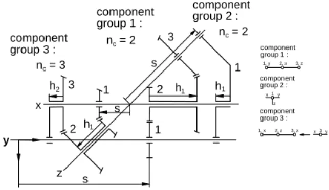
The functional representations of three com-ponent groups are shown in Fig. 7. As seen in the figures, component group 1 is made up of two gear pairs with a hub, which connects the com-mon link of them. Component group 2 is made up of two carriers with a connecting hub. Compo-nent group 3 is made up of two gear pairs and one carrier with hubs connecting them. The defi-nition of a component group is described as “gear pairs or carriers connected in series by hubs”. Since the component group is created for simpli-fying the layout process, the layout parameters of a component group, which has nc gear pairs or carriers, should be defined at the beginning of the discussion.
(1) s : location of the first gear pair or carrier where i from 1 to nc.
(2) hi : length of i-th connecting hub, which is located between the i-th and (i+1)th gear pairs or carriers where i from 1 to nc-1. Note that hi is positive or negative along the z-axis of the coordinate system, which the associ-ated hub is locassoci-ated on. Besides, A single gear pair or carrier can be treated as a component group without any connecting hubs in it, so it doesn’t have layout parameter hi.
x z 1 3 y 2 2 1 h1 h2 s s h1 component group 2 : 3 1 h1 s n = 2c component group 1 : n = 2c component group 3 : n = 3c 1, y 2, x 3, z component group 1 : 1 component group 2 : x y z 1, x 2, z 3, x component group 3 : 3 x y
Fig. 7 Three component groups
Component groups 1, 2, and 3 shown in Fig. 7 are of different types, and each of them has its own graph structure. Component group 1 is composed of two gear pairs and a connecting hub. This kind of component group is called the “gear-pair-only” component group for it not con-taining any carrier. The graph of component group 1 is composed of a heavy-edged path with link number and axis label above each vertex indicating the number of the gear link and the axis on which the gear link is located. Component group 2 is composed of two carriers and a con-necting hub. Component group of this type is called the “carrier-only” component group for it not containing any gear pair, and is actually a rigid link rotating on two or more axes. The graph representation of component group 2 is
com-posed of only one vertex (link), which is incident with at least two different-labeled edges (joints). Component group 3 is composed of two gear pairs, one carrier, and two connecting hubs. This type of component group is called the “hybrid” component group for it containing both gear pair and carrier. The graph representation of compo-nent group 3 is the combination of the “gear-pair-only” and “carrier-only” types, that is, a heavy-edged path with a vertex (or vertices) incident with at least two different-labeled thin-edges. The feature in graph of the three types of component group are concluded as follows: Type 1: a heavy-edged path without any vertex
(or vertices) incident with more than one distinct thin-edge. Component group of this type is called “gear-pair-only” com-ponent group.
Type 2: a vertex (link) incident with at least two different-labeled thin-edges (joints). Component group of this type is called “carrier-pair-only” component group. Type 3: a heavy-edged path with a vertex (or
vertices) incident with at least two differ-ent-labeled thin-edges. Component group of this type is called “hybrid” com-ponent group.
5. Sketching Modules
Since the geometry of a unit is composed of component groups, the geometrical database for the unit-level sketching modules can be estab-lished by searching component groups in the graphs of IUs and TUs shown in Table 1. Given the graph of a unit, its component group(s) can be identified throughout the following steps: (1) Search the graph for heavy-edged path(s). (2) Examine each vertex of every searched
heavy-edged path to see whether it is inci-dent with more than one distinct thin-edge. If any desired vertex exists, the searched heavy-edged path is of type 3 (hybrid) com-ponent group. If not, the searched heavy-edged path is of type 1 (gear-pair-only) com-ponent group.
(3) Search for vertex (or vertices), which is inci-dent with more than one distinct thin-edge and isn’t in any heavy-edged path(s). The searched vertex is of type 2 (carrier-only) component group.
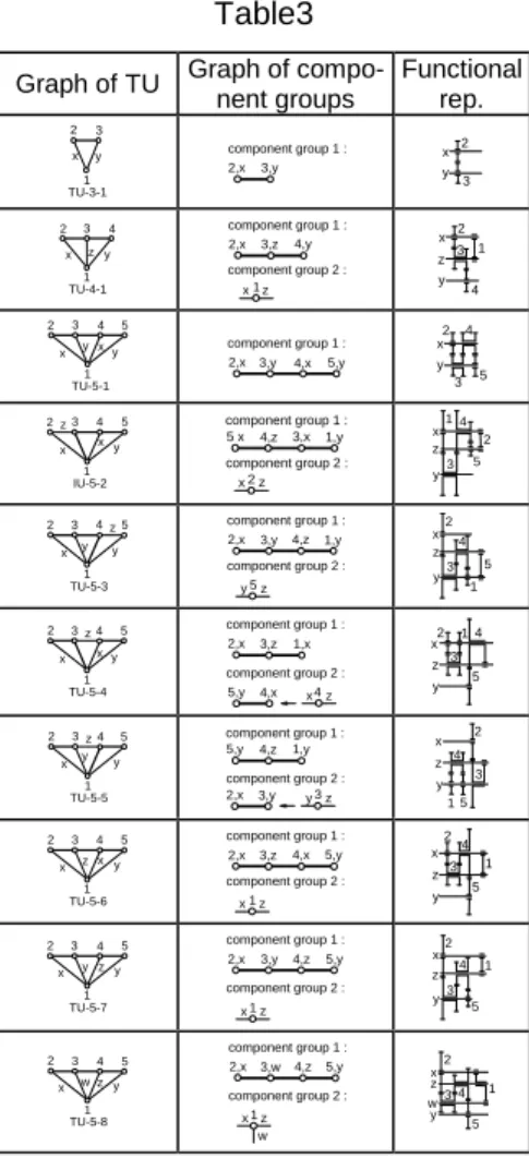
The search result, which contains all IUs and TUs in the unit atlas shown in Table 1, is listed in Tables 2 and 3. In the tables, graph and function-al representations of component groups are list-ed alongside the graph of each unit. For the rea-son of clearness, the functional representations of component groups are sketched in all-parallel-axes condition.
Table 2 Graph of
IU
Graph of
compo-nent groups Functional rep.
1 2 x IU-2-1 None None 1 2 3 4 x y x IU-4-1 2,x 3,y 4,x component group 1: x y 2 3 4 1 2 3 4 x y x IU-4-2 1,x 3,y 4,x x2y component group 1 : component group 2 : y3 x1 4 2 1 2 3 4 x y x IU-4-3 1,x 3,y 2,x x4y component group 1 : component group 2 : x y 2 3 1 4 1 2 3 4 x zx IU-5-1 5 y 2,x 3,y 4,z x1z component group 1 : component group 2 : 5,x y x z y 2 3 4 1 5 1 2 3 4 x z x IU-5-2 5 y 1,x 3,y 4,z x2z component group 1 : component group 2 : 5,x y x z y 1 3 4 2 5 1 2 3 4 x zx IU-5-3 5 y 2,x 3,y 4,z x5z component group 1 : component group 2 : 1,x y x y z 2 3 4 5 1 Table3 Graph of TU Graph of
compo-nent groups Functional rep. 2 3 x y TU-3-1 1 2,x 3,y component group 1 : x y 2 3 1 2 3 4 x z y TU-4-1 2,x 3,z 4,y x1z component group 1 : component group 2 : x y z 2 3 4 1 1 2 3 4 x x y TU-5-1 5 y 2,x 3,y 4,x component group 1 : 5,y x y 2 3 4 5 1 2 3 4 x x y IU-5-2 5 z 5 x 4,z 3,x x2z component group 1 : component group 2 : 1,y x y z 1 3 4 5 2 1 2 3 4 x z y TU-5-3 5 y 2,x 3,y 4,z y5z component group 1 : component group 2 : 1,y x y z 2 3 4 1 5 1 2 3 4 x x y TU-5-4 5 z 2,x 3,z 1,x 4,x 5,y x4z component group 1 : component group 2 : x y z 2 3 1 4 5 1 2 3 4 x z y TU-5-5 5 y 5,y 4,z 1,y 3,y 2,x y3z component group 1 : component group 2 : x y z 1 4 5 2 3 1 2 3 4 x x y TU-5-6 5 z 2,x 3,z 4,x x1z component group 1 : component group 2 : 5,y x y z 2 3 4 5 1 1 2 3 4 x z y TU-5-7 5 y 2,x 3,y 4,z x1z component group 1 : component group 2 : 5,y x y z 2 3 4 5 1 1 2 3 4 x z y TU-5-8 5 w 2,x 3,w 4,z x1z component group 1 : component group 2 : 5,y w x z y w 2 3 4 5 1
6. AGM Design Procedure
The design of a 3-dof AGM with the developed sketching program will be explained and
illustrat-ed in this chapter. The three MTLs of the desirillustrat-ed AGM are listed in Table 4 while the primary axes arrangement information is listed in Table 5. Note that θi,i-1 is not determined by the user but calcu-lated by the program, so it is not listed in Table 5.
Table 4 The MTLs of the desired 3-dof AGM
IU TU 1 TU 2
MTL 1 IU-2-1 TU-3-1 TU-3-1 MTL 2 IU-2-1 TU-5-1 None MTL 3 IU-2-1 None None Table 5 The desired axes arrangement
αi,i-1 a i,i-1 d i,i-1
i=1 45° 0 2
i=2 -45° 0 0
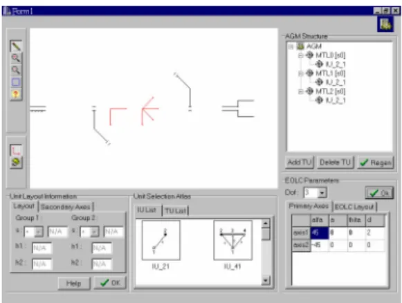
In the beginning of the design procedure, the dof of the mechanism is set as three, hence the program automatically generates the AGM with three MTL modules. Each of the three generated MTL modules has IU-2-1 as its default IU, and doesn’t have any TU in itself. Then the axes arrangement information, which is listed in table 5, is inputted to the program by the user. Ac-cording to the axes information, the program calculates the undetermined D-H parameters θ1,0 and θ2,1. At the same time, the sketching program generates a 3-joint EOLC, which is composed of a ground, an end-effector, and two carrier-only component groups. The result of the above pro-cedure is shown in Fig. 8. Afterwards, TU-3-1, which is composed of only one gear-pair-only component group, is added to the first MTL and is arranged so that it doesn’t interfere with any other existing sketching components. Next, another TU-3-1 is added to the first MTL module. The result is shown in Fig. 9. Finally, a TU-5-1 module is added to the second MTL, and the result is shown in Fig. 10. After rearrange the coaxial hubs, the design process is completed. The final AGM is shown in Fig. 11.
Fig. 8 Design procedure 1
Fig. 9 Design procedure 2
Fig. 10 Design procedure 3
Fig.11 Design procedure 4
7. Conclusion and Future works
With the methodology presented in this article, a computer-aided sketching program is devel-oped to visualize the functional representation of the AGM, which is reverse-transformed from the result of topological synthesis. In the sketching program, the data format of the functional repre-sentation of AGM is designed under the concept of modular design. Under the design concept, an AGM sketching module is divided into MTL-level modules, and MTL modules are further divided into unit-level modules. This feature enables the
sketching program to draw each module inde-pendently, thus to make the design process sim-pler and more comprehensive. By constructing the geometrical database of unit-level modules, the design process is reduced to select desired units from the database and arrange the layout of each unit-level module.
The sketching components defined in this arti-cle, which are gear pair, carrier, hub, ground, and end-effector, serve as the basic sketching ele-ments that compose the whole functional repre-sentation of the AGM. Each of the sketching components is designed so that it can be de-scribed by proper layout parameters. For en-hancing the layout easiness, component group is created to group gear pair, carrier, and hub to-gether. By identifying component group(s) in the graphs of IU and TU using proposed rules, the reverse transformation can be made, and the geometrical database of unit can be established. The computer-aided design process of a three-dof AGM is illustrated and explained at the end of this article.
The following directions are suggested to ex-tend the research:
(1) Since the layout arrangement of the sketching components are represented by parameters, the algorithm that optimizes the layout of the AGM can be developed to fulfill the ideal of automatic design environment.
(2) Based on the geometrical data format of AGM designed in this article, a computer-aided en-vironment, which generates solid models of AGM, can be developed for further kinematic and dynamic analyses.
(3) The reverse-transformation rules for the AGM developed in this article can be utilized in the field of other geared mechanisms.
8. Reference
(1) Chang S. L., and Tsai, L. W., 1990, “To-pological Synthesis of Articulated Gear Mechanisms,”IEEE Trans. On Robotics and Automation, Vol. 6, No. 1, pp. 97-103. (2) Chatterjee, G., and Tsai, L.W., 1995,
“Com-puter-Aided Sketching of Eypiyclic-type Automatic Transmission Gear Trains,” (3) Chen, D. Z., and Liu, C. P., 1999, “A
Hierar-chical Decomposition Scheme for the To-pological Synthesis of Articulated Gear Mechanisms,” Transaction of the ASME, Journal of Mechanical Design, Vol. 121, pp.256-263.
(4) Chen, D. Z., and Shiue, S. C., 1996, “ To-pological Synthesis of Geared Robotic Mechanism,”Proceedings of The 1996 AS-ME Design Engineering Technical Confer-ences and Computers in Engineering Con-ference, Paper No. 96-DETE/MECH-1024. (5) Chieng, W. H., and Hoeltzel, D. A., 1990, “A
Combinatorial Approach for the Automatic
Sketching of Planar Kinematic Chains and Epicyclic Gear Trains,” Transactions of the ASME Journal of Mechanical Design, Vol. 112, pp. 6-15
(6) Olson, D. G., Thompson, T. R., Riley, D. R., and Erdman, A. G., 1985, “An Algorithm for Automatic Sketching of Planar Kinematic Chains,”Transactions of the ASME Journal of Mechanical Design, Vol. 107, pp. 106-111.