國
立
交
通
大
學
網路工程研究所
碩
士
論
文
一個基於 IEEE 802.16j 移動式中繼站之快速
交遞行動機制
A Fast Handover Mobility Scheme over 802.16j Moving
RS Mode
研 究 生:葉盈潔
指導教授:陳耀宗 教授
一個基於 IEEE 802.16j 移動式中繼站之快速交遞行動機制
A Fast Handover Mobility Scheme over 802.16j Moving RS Mode
研 究 生:葉盈潔 Student:Ying-Chieh Yeh
指導教授:陳耀宗 Advisor:Yaw-Chung Chen
國 立 交 通 大 學
網 路 工 程 研 究 所
碩 士 論 文
A ThesisSubmitted to Institute of Network Engineering College of Computer Science
National Chiao Tung University in partial Fulfillment of the Requirements
for the Degree of Master
in
Computer Science
July 2009
Hsinchu, Taiwan, Republic of China
i
一個基於 IEEE 802.16j 移動式中繼站之快速交遞行動機制
學生:葉盈潔
指導教授:陳耀宗 博士
國立交通大學網路工程研究所
摘要
IEEE 802.16j 是基於 IEEE 802.16 網路的多躍式中繼站標準,此附加標準加入了多 躍式中繼站技術,其優點除了可以提升使用者的傳輸效能,並且能擴展通訊的涵蓋範 圍。中繼站由使用型態可以分為三種類別,分別為:固定式、遊牧式以及移動式中繼 站。其中移動式中繼站的特殊應用是將中繼站設置在大眾交通運輸工具之上,用以解 決大量使用者同時執行交遞所造成的問題。而對於涉及到網路層的交遞情境,IEEE 802.16j 標準中尚未制定出一套完善的機制,使用傳統的網路層換手機制,其過於冗長 的交遞延遲也無法滿足網路即時服務的需求。 在本篇論文中,我們提出一個嶄新的移動機制用於移動式中繼站之交遞流程。我 們增定了新的控制訊息,讓移動式中繼站和連線用戶可以相互告知交遞流程目前的執 行階段,透過訊息交換讓移動式中繼站的媒體存取控制(MAC)層、連線用戶的網路層 之交遞程序可以同步執行,進而降低整體之系統中斷時間。我們使用數學分析並設計 一套模擬實驗,數據結果顯示我們所提出的方法不僅能有效的降低系統中斷延遲,並 且降低封包遺失率。ii
A Fast Handover Mobility Scheme over 802.16j Moving RS Mode
Student:Ying-Chieh Yeh
Advisor:Dr. Yaw-Chung Chen
Institute of Network Engineering
National Chiao Tung University
Abstract
The IEEE 802.16j amendment defines specifications for multihop relay features to gain coverage extension and throughput enhancement of IEEE 802.16 networks. The usage scenarios for relay station (RS) are Fixed Relay Station (FRS), Nomadic Relay Station (NRS), and Mobile Relay Station (MRS). Among these scenarios, MRS can be mounted on mobile vehicles to simplify handover problem. However, network layer handover solutions are undefined in the amendment. Conventional handover scheme, Mobile IP, causes interruption latency which is considered too long to support real-time applications.
In this thesis, we propose a novel mobility scheme for MRS in moving RS mode and corresponding MAC management messages. Therefore, link layer and network layer handover procedures can be performed concurrently to reduce the service disruption time. We develop an analytical model and simulation to evaluate our scheme. The numerical result shows that our scheme is able to reduce the interruption latency and packet loss rate significantly.
iii
Contents
Abstract in Chinese ... i Abstract in English ... ii Contents ... iii Table List... iv Figure List ... v 1 Introduction ... 1 1.1 IEEE 802.16 Standard ... 11.2 Motivation and Purpose ... 4
1.3 Thesis Organization ... 5
2 Background ... 6
2.1 MRS Handover ... 6
2.2 Fast Mobile IPv6 ... 9
2.3 Related Works ... 12
3 Proposed Scheme ... 13
3.1 Network Model ... 13
3.2 MAC Management messages ... 14
3.3 Main Scheme ... 17 3.3.1 Predictive Mode ... 18 3.3.2 Reactive Mode ... 20 4 Numerical Analysis ... 22 4.1 Analytical Models ... 22 4.2 Numerical Results ... 25
5 Simulation and Results ... 28
5.1 Simulation environment ... 28
5.2 Simulation scenario 1 ... 29
5.3 Simulation scenario 2 ... 31
6 Conclusion ... 34
iv
Table List
Table 1.1 Comparison of 802.16j and 802.16e capabilities ... 2
Table 3.1 MRS_NBR-ADV message format ... 15
Table 3.2 MRS_HO-REQ message format ... 16
Table 3.3 MRS_HO-RSP message format ... 17
Table 3.4 MRS_HO-CLT message format ... 17
Table 4.1 Average message processing time ... 22
Table 4.2 Parameters for analysis ... 23
Table 4.3 Parameters for evaluation ... 25
Table 5.1 General parameters... 29
Table 5.2 Traffic information of simulation 1 ... 30
v
Figure List
Figure 1.1 Examples of usage scenarios for relay stations ... 3
Figure 1.2 Conventional handover process timing ... 5
Figure 2.1 Handover procedure of MRS ... 6
Figure 2.2 MRS network re-entry procedures ... 8
Figure 2.3 Network layer handover using Mobile IPv6 ... 9
Figure 2.4 FMIPv6 in predictive mode ... 10
Figure 2.5 FMIPv6 in reactive mode ... 11
Figure 3.1 Vehicular network scenario ... 13
Figure 3.2 Proposed scheme in predictive mode ... 18
Figure 3.3 Proposed schemes in reactive mode ... 20
Figure 4.1 Overlap distance between two BSs ... 25
Figure 4.2 Handover latency and disruption time ... 26
Figure 4.3 Disruption time in terms of speed ... 26
Figure 5.1 Packet sequence numbers in conventional scheme in simulation 1 ... 30
Figure 5.2 Packet sequence numbers in proposed scheme in simulation 1 ... 30
Figure 5.3 Packet sequence numbers in conventional scheme in simulation 2 ... 32
Figure 5.4 Packet sequence numbers in proposed scheme in simulation 2 ... 32
1
Chapter 1 Introduction
IEEE 802.16 standard, the so-called Worldwide Interoperability for Microwave Access (WiMAX), is one of the latest technologies to provide broadband wireless access. The main advantage of WiMAX is high bandwidth over long transmission range. The standard provides specifications for the air interface, including the medium access control (MAC) and physical (PHY) layers.
1.1 IEEE 802.16 Standard
In December 2001, IEEE 802.16-2001 standard was defined for using the frequency range of 10-66 GHz, with maximum transmission rate up to 70 Mbps or even 100 Mbps and transmission range of 20 km. However, the initial standard only supports line-of-sight (LOS) transmission. In 2003, IEEE 208.16a-2003 that can support Non-LOS (NLOS) environment and 2-11 GHz range was approved. Until 2004, IEEE 802.16 standard has revised and consolidated previous standards and evolved to the IEEE 802.16-2004 standard [1]. The standard specifies the PHY and MAC layers for fixed applications, also known as fixed WiMAX.
However, after IEEE 802.16-2004 publication, it still needs an upgrade. The main problem for IEEE 802.16-2004 is the lack of mobility features, because mobility support is considered as one of the key features in wireless network. Other features were needed and some errors had to be corrected. This gave way to IEEE 802.16e [2] published in December 2005. It is an amendment with the support of mobility and changes to the IEEE 802.16-2004 standard. This is generally known as mobile WiMAX. The main differences are mobile station (MS), MAC layer handover procedure, Orthogonal Frequency Division
2
Multiplexing (OFDMA) PHY layer, power saving, security, Adaptive Antenna System (AAS), Multiple Input Multiple Output (MIMO), Multicast and Broadcast service (MBS) feature, and Quality of Service (QoS).
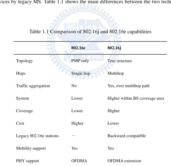
In March 2006, IEEE 802.16 Relay Task Group [3] was established, which developed multihop relay amendment called IEEE 802.16j. The seventh draft, IEEE 802.16j-D7 [4] was released in October 2008. It provides specifications for multihop relay features in order to gain the promising advantages including coverage extension and throughput enhancement to WiMAX system. The solutions can operate with legacy IEEE 802.16e end terminal devices, new base station (BS) and relay station (RS) to be realized and provide services by legacy MS. Table 1.1 shows the main differences between the two technologies [5].
Table 1.1 Comparison of 802.16j and 802.16e capabilities
802.16e 802.16j
Topology PMP only Tree structure
Hops Single hop Multihop
Traffic aggregation No Yes, over multihop path
System Lower Higher within BS coverage area
Coverage Lower Higher
Cost Higher Lower
Legacy 802.16e stations - Backward compatible
Mobility support Yes Yes
PHY support OFDMA OFDMA extension
3
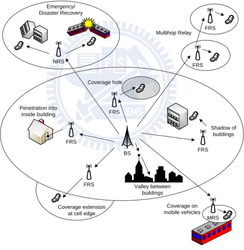
1.1 [6]. In the fixed infrastructure usage model, fixed RSs (FRS) are deployed in order to provide coverage extension at cell edge, to provide coverage for indoor users, to provide coverage for users in coverage holes that in shadow or valleys between buildings, and to provide access for clusters of users outside the coverage area of the BS. Nomadic RSs (NRS) are deployed temporarily to provide additional coverage or capacity in some areas where BSs and/or fixed RSs do not provide sufficient coverage or capacity. Examples of temporary coverage can be required of emergency, disaster recovery situations, or special event or fairs which require the coverage be provided for the duration of the event.
BS FRS FRS FRS FRS FRS FRS MRS NRS Coverage extension at cell edge Penetration into inside building Coverage hole Valley between buildings Shadow of buildings Multihop Relay Emergency/ Disaster Recovery Coverage on mobile vehicles
Figure 1.1 Examples of usage scenarios for relay stations
A mobile RS (MRS) can work in either moving RS mode or moving BS mode. In moving RS mode, MRS can be mounted on a vehicle, such as a bus or a train, connected to a BS via a mobile link. In this case, the RS provides a fixed access link to end terminals
4
riding on the vehicle. Different from moving RS mode, in moving BS mode, MRS has network access capability completely. Working as a mobile router (MR), MRS in moving BS mode can assign IP address and connection identifier (CID) to each MS which connected to it, therefore only the MRS has to perform both MAC layer (layer 2) and network layer (layer 3) handover procedure, MS is not aware that there is a handover event. However, moving BS mode actually simplifies the handover procedure, but that will add much more hardware costs to MRS. IEEE 802.16j will basically perform moving RS mode. In this thesis, we will focus on MRS in moving RS mode.
1.2 Motivation and Purpose
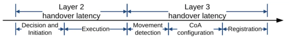
In a network layer handover, the MRS involved in different IP subnets or in different networks. Thus, in a network layer handover, a MS needs to establish a new care of address (CoA) configuration and registration to maintain connectivity. In moving RS mode, MS must wait for MRS finished MAC layer handover procedure, then MS can perform CoA confirmation which takes at least 1 second using Mobile IPv6 [7]. The handover causes interruption latency too long to support real-time applications such as voice over Internet Protocol (VoIP) or video streaming, etc. The handover process timing using conventional handover scheme is shown in Figure 1.2.
To overcome the problem described above, in this thesis, we propose a new mobility scheme for MRS in moving RS mode and corresponding MAC management messages. We focus on MRS moving between different IP subnets. Our goal is to make link layer and network layer handover procedures be performed concurrently to reduce the service disruption time so that users can get satisfactory Quality of Experience while using real-time application services over WiMAX.
5 Layer 2 handover latency Layer 3 handover latency Decision and
Initiation Execution Registration Movement
detection
CoA configuration
Figure 1.2 Conventional handover process timing
1.3 Thesis Organization
The rest of this thesis is organized as follows. Chapter 2 presents an overview of IEEE 802.16j system architecture and the background about handover schemes in WiMAX. Next, Chapter 3 discusses the mobility scheme we proposed in details. In Chapter 4, we evaluate our scheme through numerical analysis. The simulation and results are presented in Chapter 5.
6
Chapter 2 Background
In this chapter, we briefly describe the IEEE 802.16j MRS features, focusing on those characteristic that are relevant to this thesis. Next we shortly describe the Fast Mobile IPv6 [8]. At the end we review some literatures related to the handover issues.
2.1 MRS Handover
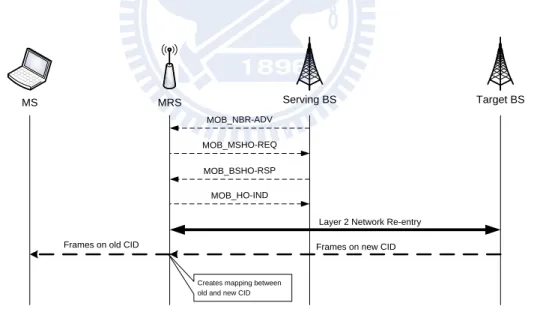
IEEE 802.16j defines a handover process which may occur when the MS/MRS moves and needs to change the BS for higher signal quality or better QoS. The handover procedure can be decomposed into three phases: Handover preparation, Handover decision and initiation, and Handover execution. MRS Handover procedure is illustrated in Figure 2.1.
MS MRS Serving BS Target BS
MOB_NBR-ADV
MOB_MSHO-REQ
MOB_BSHO-RSP
MOB_HO-IND
Layer 2 Network Re-entry
Frames on new CID Frames on old CID
Creates mapping between old and new CID
Figure 2.1 Handover procedure of MRS
The handover preparation phase includes network topology advertisement, scanning and association procedure. During network topology advertisement procedure, a BS needs to broadcast information regarding the network topology through MOB_NBR-ADV (neighbor advertisement) MAC management message. The purpose of the message is to
7
provide a MRS with the current network identification, to provide information about neighboring BSs, and to facilitate MRS synchronization with neighboring BSs. According to this information, the MRS can make an immediate decision for a future handover. If necessary, a MRS may perform a scanning procedure to find and monitor the suitable neighboring BSs as a target for a handover. MRS scanning is based on exchanging MOB_SCN-REQ (scanning interval allocation request) and MOB_SCN-RSP (scanning interval allocation response) messages. The MOB_SCN-REQ message is sent by MRS to request a scanning interval for the purpose of finding available BSs and determining their target for handover. Association procedure is an optional initial ranging procedure occurring during the scanning interval with respect to one of the neighbor BSs.
A handover begins with a decision for a MRS will have a handover from serving BS to target BS. The decision may originate at the MRS or the serving BS by sending a MOB_MSHO-REQ (MS handover request) or MOB_BSHO-REQ (BS handover request) messages. In the case of MRS initiated handover, the serving BS replies MOB_BSHO-RSP message with recommended target BSs to the MRS, and sends the MAC addresses and CIDs of the MSs under MRS to the target BS over the backbone.
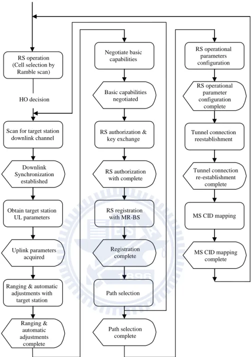
Handover execution occurs after handover initiation phase. The MRS selects the target BS and sends MOB_HO-IND (handover indication) message to indicate a handover to serving BS. After MRS sends MOB_HO-IND message, no packet transfer between the MRS and the serving BS is allowed. Next, MRS performs downlink synchronization, raging, and network re-entry to the target BS. The BS assigns new CIDs for MSs and sends it to MRS by RNG-RSP (ranging response) message, then MRS creates mapping between old and new CID for each MS. After handover execution phase, the target BS becomes the serving BS and starts to provide service to the MRS. Figure 2.2 shows the MRS’ handover process [4].
8
Figure 2.2 MRS network re-entry procedures
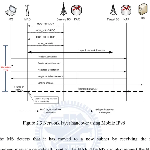
If the MRS moves to a different subnet, the MS under the MRS must re-configure a new IP address, CoA address, and re-establish its IP connection based on the new IP address. However, the MS has to wait for the MRS switches to the target link and the MS can realize that it moved to a different subnet. Then, the MS performs the network layer handover, through a network layer mobility mechanism, such as Mobile IPv6. The handover procedure involved in network layer is shown in Figure 2.3.
RS operation (Cell selection by
Ramble scan)
HO decision
Scan for target station downlink channel
Downlink Synchronization
established
Obtain target station UL parameters
Uplink parameters acquired
Ranging & automatic adjustments with target station Ranging & automatic adjustments complete Negotiate basic capabilities Basic capabilities negotiated RS authorization & key exchange RS authorization with complete Path selection RS registration with MR-BS Registration complete Path selection complete RS operational parameters configuration Tunnel connection reestablishment Tunnel connection re-establishment complete MS CID mapping MS CID mapping complete RS operational parameter configuration complete
9
MS MRS Serving BS PAR Target BS NAR
MOB_NBR-ADV Router Solicitation Router Advertisement MOB_MSHO-REQ MOB_BSHO-RSP MOB_HO-IND
Layer 2 Network Re-entry
Frame on new CID
HA Neighbor Solicitation Neighbor Advertisement Binding Update Frame on old CID Disruption Time
Creates mapping between old and new CID
MAC layer handover messages
IP layer handover messages
Figure 2.3 Network layer handover using Mobile IPv6
The MS detects that it has moved to a new subnet by receiving the router advertisement message periodically sent by the NAR. The MS can also request the NAR to send router advertisement by sending router solicitation message. After exchanging these messages, MS obtains the information to create a new CoA and confirms its CoA by neighbor solicitation message. After CoA confirmation is finished, the MS must update the binding cache in its home agent (HA) by sending binding update message.
However, both two layer handover mechanism operate alternately, that brings long handover disruption latency, which is unacceptable for the real-time applications.
2.2 Fast Mobile IPv6
Fast Mobile IPv6 (FMIPv6) is proposed to reduce the handover latency for the real-time traffic by movement detection and address configuration procedures. FMIPv6
10
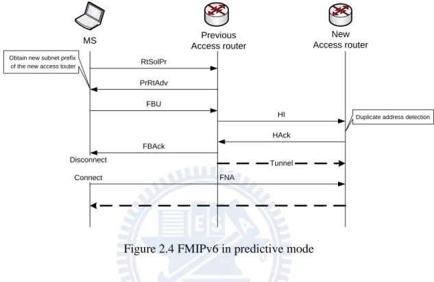
enables a MS quickly realizes that it is moving to a new subnet and performs CoA configuration early by providing the subnet network prefix information of associated access router (AR). Figure 2.4 shows the FMIPv6 handover procedure.
MS Previous Access router New Access router RtSolPr PrRtAdv Tunnel FBU HAck HI FBAck FNA Disconnect Connect
Obtain new subnet prefix of the new access touter
Duplicate address detection
Figure 2.4 FMIPv6 in predictive mode
After the MS discovers a new neighbor BS by MOB_NBR-ADV message, it may perform scanning in order to determine the BSs that are available. The MS then selects one of the candidate BSs and obtains new subnet prefix of the target BS by exchange the RtSolPr (router solicitation for proxy) and PrRtAdv (proxy router advertisement) messages with previous AR (PAR). On receiving PrRtAdv message, the MS configures its CoA, based on the subnet prefix obtained from this message.
When MS decides an impending handover, it sends a FBU (fast binging update) message to the PAR to notify the router that there is a binding between previous CoA at the current subnet and new CoA at the target subnet. Next, the PAR sends HI (handover initiation) message to the new AR (NAR) for CoA confirmation procedure. After NAR receives HI message, it executes the CoA confirmation, duplicate address detection (DAD), procedure and replies HAck (handover acknowledge) message to the PAR. At the same time,
11
the tunnel between the previous CoA of MS and its new CoA at the NAR is established. The NAR receives the tunneled packets and stores them in a buffer until it receives FNA (fast neighbor advertisement) message from the MS, then it delivers the buffered packets to the MS. The FNA message is sent after the MS conducts handover to the target BS and performs the network re-entry procedure.
On receiving HAck message, PAR sends FBAck (fast binding acknowledgement) message to the MS. If the MS receives this message before its handover and sends MOB_HO-IND message as a final indication of handover, the predictive mode of FMIPv6 is enabled. The predictive FMIPv6 makes the MS to move to the new subnet and receive packets from the NAR quickly. If the MS does not receive FBAck message before it is forced to move to the new subnet, reactive mode will be occurred. In reactive mode, the MS has to wait for packet rerouting to be executed then it can receive packets from the NAR. Figure 2.5 shows the FMIPv6 in reactive mode.
MS Previous Access router New Access router RtSolPr PrRtAdv Tunnel FBU FBU FBAck FNA[FBU] Disconnect Connect
Figure 2.5 FMIPv6 in reactive mode
FMIPv6 proposed a quickly handover mechanism for MS moving to a different subnet. However, FMIPv6 is mainly designed for the node mobility scenarios.
12
2.3 Related Works
Recently, there are several proposals concerning handover scheme for broadband wireless access network based on IEEE 802.16 standards. Most of these proposals aim to reduce the handover disruption latency.
Yang et al. proposed a protocol for de-centralized multihop relay networks [9]. This protocol reduces the MAC management message overhead transferred on the wireless links. Becvar et al. suggested a handover scheme that optimized the scanning procedure to reduce the management information overhead and to maximize the user data throughput [10]. Jiao et al. proposed a MAC layer QoS aware handover scheme [11]. This scheme makes downlink data transmission interruption brief and reduces uplink data transmission delay. They provided MAC layer solutions that only reduce MAC layer latency. However, the effect of simplifying the MAC layer handover procedure does not adequately reduce the overall handover latency.
To overcome the problem, Zhong et al. proposed an integrated fast handover scheme over the IEEE 802.16e system which supports network mobility (NEMO) [12]. This scheme provides transparent network access through the MR and performs both the MAC and network layers concurrently. The MR needs to have network layer capacities and performs network layer handover for MS that causes high costs and brings more complex in MR.
Some works apply mobility management to different network systems. Kumar et al. proposed a fast handover mechanism based on IEEE 802.16m (WiMAX II) standard which supports high speed movement [13]. Ail et al. presented the mobility issues over 3GPP system [14].
13
Chapter 3 Proposed Scheme
As mentioned in previous chapters, handover process causes disruption latency. Long disruption latency problem is unacceptable for the real-time applications such as VoIP and video streaming. We propose a new handover scheme and corresponding MAC management messages to reduce the system disruption time. In this chapter, we present a network model and describe our scheme in detail.
3.1 Network Model
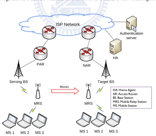
We propose a mobility scheme based on IEEE 802.16j mobile vehicle usage model that is compatible with FMIPv6. The typical scenario is a vehicular network, provides MRS and MS travel together on a mobile vehicle, such as a bus or a train, as shown in Figure 3.1.
ISP Network Serving BS MRS Target BS MRS MS 1 MS 2 MS 3 MS 1 MS 2 MS 3 Moves HA Authentication server PAR NAR
HA: Home Agent AR: Access Router BS: Base Station MRS: Mobile Relay Station MS: Mobile Station
14
A MRS is mounted on a vehicle and moving around with MS attached to it. The MS may be mobile devices of the passengers on this vehicle. When the MRS moves from serving BS to target BS belonging to a different subnet, it involved in a network layer handover. In this case, the MRS provides a fixed access link to the MS so there is no MAC layer handover occurs on this link. A MS only needs to perform network layer handover procedures from PAR to NAR using FMIPv6. The MRS simply performs MAC layer handover instead of both MAC and network layer handover in moving BS mode.
In this scenario, different from FMIPv6, MAC layer handover and network layer handover procedures are performed by different devices. In FMIPv6, MAC layer and network interaction by event trigger in a protocol stack. However, in our network, it needs MAC layer message transmission between MRS and MS. Therefore, we propose a mobility scheme and corresponding MAC management messages in order to perform link layer and network layer handover procedures concurrently.
3.2 MAC Management messages
In this section we propose the handover related MAC management messages for the interaction between MRS and MS.
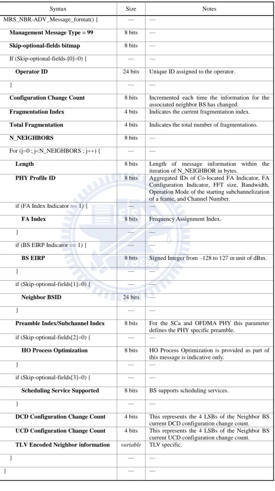
In 802.16j system, the BS broadcasts information about the network topology by MOB_NBR-ADV message periodically. MRS obtains information of neighbor BS which is necessary to determine the target BS. In our scheme, MRS should broadcast information about neighbor BS to MS, so that MS can perform CoA configuration process. Therefore, we propose MRS_NBR-ADV (mobile relay station neighbor advertisement) message that MRS can send network topology information and characteristics of neighboring BS to MS. We define MRS_NBR-ADV message format which is compatible with IEEE 802.16j network as shown in Table 3.1 [2].
15
Table 3.1 MRS_NBR-ADV message format
Syntax Size Notes
MRS_NBR-ADV_Message_format() { — —
Management Message Type = 99 8 bits —
Skip-optional-fields bitmap 8 bits —
If (Skip-optional-fields-[0]=0) { — —
Operator ID 24 bits Unique ID assigned to the operator.
} — —
Configuration Change Count 8 bits Incremented each time the information for the associated neighbor BS has changed.
Fragmentation Index 4 bits Indicates the current fragmentation index.
Total Fragmentation 4 bits Indicates the total number of fragmentations.
N_NEIGHBORS 8 bits —
For (j=0 ; j<N_NEIGHBORS ; j++) { — —
Length 8 bits Length of message information within the iteration of N_NEIGHBOR in bytes.
PHY Profile ID 8 bits Aggregated IDs of Co-located FA Indicator, FA Configuration Indicator, FFT size, Bandwidth, Operation Mode of the starting subchannelization of a frame, and Channel Number.
if (FA Index Indicator == 1) { — —
FA Index 8 bits Frequency Assignment Index.
} — —
if (BS EIRP Indicator == 1) { — —
BS EIRP 8 bits Signed Integer from –128 to 127 in unit of dBm.
} — —
if (Skip-optional-fields[1]=0) { — —
Neighbor BSID 24 bits —
} — —
Preamble Index/Subchannel Index 8 bits For the SCa and OFDMA PHY this parameter defines the PHY specific preamble.
if (Skip-optional-fields[2]=0) { — —
HO Process Optimization 8 bits HO Process Optimization is provided as part of this message is indicative only.
} — —
if (Skip-optional-fields[3]=0) { — —
Scheduling Service Supported 8 bits BS supports scheduling services.
} — —
DCD Configuration Change Count 4 bits This represents the 4 LSBs of the Neighbor BS current DCD configuration change count.
UCD Configuration Change Count 4 bits This represents the 4 LSBs of the Neighbor BS current UCD configuration change count.
TLV Encoded Neighbor information variable TLV specific.
} — —
16
In our scheme, when MRS or BS initiated a handover belonging to a different subnet, MRS should notify MS that there is an impending handover. The MS then performs CoA confirmation procedure with the PAR. So we propose MRS_HO-REQ (mobile relay station handover request) message which offers the recommended target BS information. After MRS receives MOB_BSHO-RSP message from serving BS with recommended target BS, then forwards this information to MS. We defines MRS_HO-REQ message format as shown in Table 3.2.
Table 3.2 MRS_HO-REQ message format
Syntax Size Notes
MRS_HO-REQ_Message_format() { — —
Management Message Type = 100 8 bits —
N_Recommended 8 bits —
For (j=0 ; j<N_Recommended ; j++) { — —
Neighbor BSID 48 bits —
Preamble index/ Preamble Present and Subchannel Index
8 bits For the SCa and OFDMA PHY this parameter
defines the PHY specific preamble for the neighbor BS.
Service level prediction 8 bits —
HO process optimization 8 bits —
Network Assisted HO supported 1 bit Indicates that the BS supports Network Assisted HO.
HO_ID_included_indicator 1 bit Indicates if the field HO_IND is included.
if (HO_ID_included_indicator == 1) { — —
HO_ID 8 bits ID assigned for use in initial ranging to the target BS once this BS is selected as the target BS.
} — —
HO_authorization policy indicator 1 bit To indicate if authorization negotiation is used in HO procedure.
Reserved 4 bits Shall be set to zero.
if (HO_authorization policy indicator == 1) { — —
HO_authorization_policy_support 8 bits Signed Integer from –128 to 127 in unit of dBm.
} — —
} — —
TEMP_BSID_Anchor 3 bits Temp BSID for Anchor BS.
AK Change Indicator 1 bit To indicate whether the AK being used should change when switching to a new Anchor BS.
17
Our proposed MRS_HO-RSP (mobile relay station handover response) message is used to notify MRS that MS has finished the CoA confirmation procedure. Each MS under the MRS needs to send MRS_HO-RSP message to MRS after it receives FBAck message. Table 3.3 shows MRS_HO-RSP message format we defined. Note that if some MSs has not sent this message, but the MRS needs to execute the handover immediately, it may cause some MSs to perform handover in predictive mode and others handover in reactive mode.
Table 3.3 MRS_HO-RSP message format
Syntax Size Notes
MRS_HO-RSP_Message_format() { — —
Management Message Type = 101 8 bits —
} — —
We define a new MAC management message, MRS_HO-CLT (mobile relay station handover complete), so that MRS can inform MS that it has successfully attached to target BS and MS can deliver and receive packets with NAR. Table 3.4 shows MRS_HO-CLT message format we define.
Table 3.4 MRS_HO-CLT message format
Syntax Size Notes
MRS_HO-CLT_Message_format() { — —
Management Message Type = 102 8 bits —
} — —
3.3 Main Scheme
In this section, the proposed mobility scheme over 802.16j network is shown for both predictive and reactive mode. It is assumed that the handover scenario is the network model we present in previous section. For convenience, we discuss only one MS attached to the
18
MRS. Actually it makes no difference to our scheme whether there is more than one MS.
3.3.1 Predictive Mode
The handover procedures in the predictive mode are described as follows. Figure 3.2 illustrates these procedures.
MS MRS Serving BS PAR Target BS NAR
MOB_NBR-ADV MRS_NBR-ADV RtSolPr PrRtAdv MOB_MSHO-REQ MOB_BSHO-RSP MRS_HO-REQ FBU FBAck HI HAck Tunnel MRS_HO-RSP MOB_HO-IND
MAC Layer Network Re-entry
MRS_HO-CLT
FNA
MAC layer handover messages
IP layer handover messages
Figure 3.2 Proposed scheme in predictive mode
1. The serving BS broadcasts MOB_NBR-ADV message periodically.
2. MRS generates MRS_NBR-ADV message according to the information in MOB_NBR-ADV message and sends to MS.
3. When a new BS is found, the MS requests the new subnet prefix of the target BS by an exchange of RtSolPr and PrRtAdv messages with the PAR.
19
4. The MRS initiates handover by sending MOB_MSHO-REQ message to the serving BS and receives MOB_BS-RSP from the serving BS. Alternatively, the serving BS can initiate handover by sending MOB_BSHO-REQ message to MRS. 5. MRS sends MRS_HO-REQ to notify MS that there is an impending handover that
the target BS belongs to a different subnet.
6. On reception of MRS_HO-REQ message, the MS sends FBU message to the PAR. This message provides the CoA configured by MS. On receiving this message, the PAR establishes a tunnel between the current CoA and the new CoA by exchange of HI and HAck message with the NAR and it forwards the packets destined for the current CoA to the new CoA. During this time, the NAR confirms that the new CoA is unique in the new subnet by performing DAD process. After the tunnel is established, the PAR sends FBAck message to MS.
7. After MS receives the FBAck massage, it sends MRS_HO-RSP message to notify MRS that MS has finished the CoA confirmation procedure.
8. The MRS receives MRS_HO-RSP message before its handover and sends MOB_HO-IND message as a final indication of handover. Afterwards it operates in predictive mode in the new link.
9. The MRS conducts handover to the target BS and performs the IEEE 802.16j MRS network re-entry procedure. After finished network re-entry procedure, the MRS sends MRS_HO-CLT message to MS.
10. On receiving MRS_HO-CLT message, the MS sends FNA message to the NAR. 11. When NAR receives the FAN from the MS, it delivers the buffered packets to the
20
3.3.2 Reactive Mode
This section describes the handover procedures in the reactive mode. Figure 3.3 shows these procedures.
MS MRS Serving BS PAR Target BS NAR
MOB_NBR-ADV MRS_NBR-ADV RtSolPr PrRtAdv MOB_MSHO-REQ MOB_BSHO-RSP MRS_HO-REQ FBU FBU FBAck Tunnel MOB_HO-IND
MAC Layer Network Re-entry MRS_HO-CLT
FNA[FBU]
MAC layer handover messages
IP layer handover messages
Figure 3.3 Proposed schemes in reactive mode
1. ~ 5. It is same as the procedure of predictive mode.
6. On reception of MRS_HO-REQ message, the MS sends FBU message to the PAR, but MS does not receive FBAck message before MRS sends MOB_HO-IND message as a final indication of handover. Afterwards it operates in reactive mode in the new link.
7. The MRS conducts handover to the target BS and performs the IEEE 802.16j MRS network re-entry procedure. After finished network re-entry procedure, the MRS
21
sends MRS_HO-CLT message to MS.
8. Upon receiving MRS_HO-CLT message, the MS sends FNA message to the NAR, with an encapsulated FBU message.
9. Upon receiving the FNA message, the NAR verifies the availability of the new CoA by performing DAD and forwards the inner FBU message to PAR to establish a packet tunnel.
10. After PAR sends an FBAck message to the NAR as a reply to the FBU message, the PAR starts to tunnel the packets destined for the old CoA to the new CoA.
22
Chapter 4 Numerical Analysis
In this chapter, we analyze the handover latency in our scheme and in the conventional handover using Mobile IPv6.
4.1 Analytical Models
We design an experiment to measure the message processing time by developing a C++ program and executing on a layer 2 device (WL-320gE). For each message, we execute 1 million times and calculate the average message processing time that is shown in Table 4.1.
Table 4.1 Average message processing time
Message Type Processing time (ms)
MOB_NBR_ADV 5.2×10⁻⁴ MOB_BSHO_RSP 2.34×10⁻³ MRS_HO_RSP 6.8×10⁻⁴ MRS_NBR_ADV 5.2×10⁻⁴ MRS_HO_REQ 1.51×10⁻³ MRS_HO_CLT 1.07×10⁻³
There are some reasonable assumptions in our model. In IEEE 802.16j, the interaction of the message is based on the duration of a frame. Since the message processing time (about 10-3 ms) is less than the frame duration, we assume that the message transmission delay in the network nodes is at least one-frame duration long. The radio propagation delay
23
(about 10-2 ms) is very small, so we omitted it in our analysis. We describe the parameters for numerical analysis in Table 4.2.
Table 4.2 Parameters for analysis
Parameter Description
Tframe Frame duration of IEEE 802.16j
TL2_entry Latency of IEEE 802.16j network re-entry procedure Thop Latency of every routing hop in wired backbone network Tdad Latency of DAD procedure
Tbs_ar Transmission delay between BS and AR Npar_nar Number of hop between NAR and PAR
Nnar_ha Number of hop between NAR and HA
Dolap Overlap distance between Serving and Target BS v Velocity of MRS
Handover latency is defined as the elapsed time between handover starts and MS can
deliver and receive packets through the NAR. This interval includes the Handover preparation, Handover decision and initiation, and Handover execution phases. In our scheme, the handover process starts when the serving BS sends MOB_NBR-ADV message. Message transmission delay between serving BS and MRS is Tframe as our previous
assumption, and message transmission delay between PAR and MS takes 2Tframe+ Tbs_ar.
Therefore, the overall handover latency of proposed scheme in predictive mode can be expressed as Equation (1).
24
In reactive mode, handover latency of proposed scheme is expressed as Equation (2).
17𝑇𝑓𝑟𝑎𝑚𝑒 + 5𝑇𝑏𝑠_𝑎𝑟 + 2 × 𝑇𝑝𝑎𝑟 _𝑛𝑎𝑟 + 1 × 𝑇ℎ𝑜𝑝 + 𝑇𝑑𝑎𝑑 + 𝑇𝐿2_𝑒𝑛𝑡𝑟𝑦 (2)
Similarly, the conventional handover latency using Mobile IPv6 is expressed as Equation (3).
16𝑇𝑓𝑟𝑎𝑚𝑒 + 6𝑇𝑏𝑠_𝑎𝑟 + 2 × 𝑇𝑛𝑎𝑟 _ℎ𝑎 + 1 × 𝑇ℎ𝑜𝑝 + 𝑇𝑑𝑎𝑑 + 𝑇𝐿2_𝑒𝑛𝑡𝑟𝑦 (3)
Disruption time is defined as the elapsed time between MS receiving the last packet
from PAR and the first packet from NAR. When MRS sends MOB_HO-IND message, MRS cannot receive packets from the serving BS. The disruption time of proposed scheme in both predictive mode and reactive mode are given in Equation (4) and (5).
6𝑇𝑓𝑟𝑎𝑚 𝑒+ 2𝑇𝑏𝑠_𝑎𝑟 + 𝑇𝐿2_𝑒𝑛𝑡𝑟𝑦 (4)
6𝑇𝑓𝑟𝑎𝑚𝑒 + 2𝑇𝑏𝑠_𝑎𝑟 + 2 × 𝑇𝑝𝑎𝑟 _𝑛𝑎𝑟 + 1 × 𝑇ℎ𝑜𝑝 + 𝑇𝑑𝑎𝑑 + 𝑇𝐿2_𝑒𝑛𝑡𝑟𝑦 (5)
In conventional handover scheme, the disruption time is given as in Equation (6).
13𝑇𝑓𝑟𝑎𝑚𝑒 + 6𝑇𝑏𝑠_𝑎𝑟 + 2 × 𝑇𝑛𝑎𝑟 _ℎ𝑎 + 1 × 𝑇ℎ𝑜𝑝 + 𝑇𝑑𝑎𝑑 + 𝑇𝐿2_𝑒𝑛𝑡𝑟𝑦 (6)
In the proposed scheme, the disruption time is affected by the speed of MRS. If the MRS moves very fast, MS does not receive FBAck message before MRS has to send MOB_HO-IND message as a final indication of handover. The handover process operates in reactive mode that may cause longer disruption latency. Therefore, the overlap distance between two BSs affects the disruption time. The overlap distance is illustrated in Figure 4.1.
25 Serving BS MRS Target BS MS 1 MS 2 MS 3 Dolap
Figure 4.1 Overlap distance between two BSs
While a MRS is moving in the overlap area, it performs the handover preparation, handover decision and initiation procedures. At the edge of this area, MRS must execute the handover process. So the relation of overlap distance, speed of MRS and handover preparation latency (𝑇) is expressed as Equation (7).
𝐷𝑜𝑙𝑎𝑝 ≥ 𝑣 × 𝑇 (7)
4.2 Numerical Results
In this section, we present the results based on the previous analysis. The parameter values used in numerical analysis are shown in Table 4.3.
Table 4.3 Parameters for evaluation
Tframe TL2_entry Thop Tdad Tbs_ar Npar_nar Nnar_ha Dolap
26
Handover latency and disruption time in both modes of proposed scheme and in conventional scheme is shown in Figure 4.2. We can find clearly that the handover latency of proposed scheme is a little longer than conventional scheme, because it has additional preparation process in our scheme. However, the disruption time of proposed scheme in predictive mode is much lower than that in conventional scheme, because our scheme performs CoA confirmation early in predictive mode.
Figure 4.2 Handover latency and disruption time
The effect of the speed of MRS on the disruption times of proposed scheme and conventional scheme is shown in Figure 4.3.
Figure 4.3 Disruption time in terms of speed 0 200 400 600 800 1000 1200 1400 1600
Proposed_Predictive Proposed_Reactive Conventional
Ti
m
e
(m
s)
Handover Latency Disruption Time
0 200 400 600 800 1000 1200 1400 5 20 35 50 65 80 95 110 125 D isr up ti o n Ti m e (m s) Velocity of MRS (km/h) Conventional Proposed
27
In our proposed scheme, it has enough time to initiate fast handover in predictive mode for MRS speed up to 115 km/h, but over 115 km/h it has to switch to the reactive mode. On the other hand, the conventional scheme has much higher disruption time than that in proposed scheme. Even in reactive mode, our proposed scheme still has lower disruption time than the conventional scheme. However, generally the MRS will not move in such high speed most of the time.
28
Chapter 5 Simulation and Results
This chapter introduces the simulation environment first, and then we present the simulation results in conventional scheme and proposed scheme. In each simulation scenario, we compare the handover disruption latency and packet loss rate of the two schemes.
5.1 Simulation environment
We perform simulation with NS-2 (version 2.29) simulation tool [15] with Seamless and Secure Mobility Module which is designed and developed by the National Institute of Standards and Technology (NIST) [16] and Light WiMAX Simulator (LWX) Module which supports IEEE 802.16 and IEEE 802.16j.
LWX provides 802.16 MAC functionalities with QoS, different modulation coding rates, and traffic relay supports. LWX also provides several bandwidth allocation algorithms for 802.16 and 802.16j networks including strict priority and round robin bandwidth algorithms for basic 802.16 networks and round robin bandwidth algorithm for 802.16j relay network [17]. We implement the MRS features, proposed MAC management messages and proposed handover solution in the NS-2 simulator.
The topology considered for simulation as the network model is presented in Figure 3.1, it consists of a MRS mounted on a vehicle and moving with MS. The MRS moves from serving BS to target BS belonging to a different IP subnet in the same ISP network. We present several simulation scenarios to analyze the proposed scheme and conventional scheme. Regardless of different simulation scenarios, the general parameters are the same and they are presented in Table 5.1.
29
Table 5.1 General parameters
Parameter Value
Channel type WirelessChannel
Radio propagation model TwoRayGround Network interface type WirelessPhy
MAC type LWX
Interface queue type PriQueue
Link layer type LL
Antenna model OmniAntenna
Max packet in ifq 50
Routing protocol AODV
Bandwidth allocation algorithm Round Robin for Relay
Framd duration 5 ms
Traffic type UDP/CBR
5.2 Simulation scenario 1
In this simulation, we want to ensure that the handover scheme works well for the VoIP service and shows better handover disruption latency and packet loss rate than the conventional scheme. Table 5.2 presents the traffic information. To simplify the simulation, the MS only has one service flow connection. The traffic source produces the traffic rate in 64 Kbps and the packets in 200 bytes size.
30
Table 5.2 Traffic information of simulation 1
Packet size Rate Bandwidth
Max Min
200 bytes 64 Kbps 80 Kbps 50 Kbps
We give each packet a sequence number, by keeping track of packet sequence numbers that MS received, so that we can observe the packet loss occurred. Figure 5.1 and 5.2 show the simulation results in both schemes.
Figure 5.1 Packet sequence numbers in conventional scheme in simulation 1
Figure 5.2 Packet sequence numbers in proposed scheme in simulation 1 0 20 40 60 80 100 120 0 0.5 1 1.5 2 2.5 3 3.5 Se qu enc e N um be r Time (s) 0 20 40 60 80 100 120 0 0.5 1 1.5 2 2.5 3 3.5 Se qu enc e N um be r Time (s)
31
In Figure 5.1, during handover period the mobile node is unable to receive any packet from service provider. The disruption latency is about 1.25 seconds of the conventional scheme and there is no mechanism for buffering so every packet is lost.
On the other hand, in Figure 5.2 the proposed scheme is used. The PAR buffers the packets, and forwards them into the tunnel, so that the MS can receive packets before handover procedure is finished. We can observe that the disruption latency is about 0.225 seconds, and the packet loss rate in our proposed scheme is much lower than that in the conventional scheme. The disruption latency can be reduced by 82% in our scheme.
For VoIP service, the shorter handover disruption latency means a higher quality of experience (QoE). By reducing the service disruption time the users can experience a better quality.
5.3 Simulation scenario 2
In this simulation, we want to ensure that the handover scheme works well for the video streaming service and shows better handover disruption latency and packet loss rate than the conventional scheme. Table 5.3 presents the traffic information. To simplify the simulation, the MS only has one service flow connection. The traffic source produces the traffic rate 1 Mbps and the packet size for 1500 bytes.
Table 5.3 Traffic information of simulation 2
Packet size Rate Bandwidth
Max Min
1500 bytes 1 Mbps 4 Mbps 2 Mbps
32
The results are shown in Figure 5.3 and 5.4 in both schemes.
Figure 5.3 Packet sequence numbers in conventional scheme in simulation 2
Figure 5.4 Packet sequence numbers in proposed scheme in simulation 2
We compare the results with simulation 1. The proposed scheme has better performance also in video streaming service. In Figure 5.3, every packet is lost during handover. While in our proposed scheme, we reduce the service disruption time successfully. Besides, we can find that the PAR buffers the packets and forwards them in the tunnel, so MS receive the packets after handover process is finished. The disruption time of simulation 1 and 2 are shown in Figure 5.5.
0 100 200 300 400 500 0 0.5 1 1.5 2 2.5 3 3.5 Se qu enc e N um be r Time (s) 0 100 200 300 400 500 0 0.5 1 1.5 2 2.5 3 3.5 Se qu enc e N um be r Time (s)
33
Figure 5.5 Disruption time of simulation 1 and 2 0 200 400 600 800 1000 1200 1400
Proposed Scheme Conventional
Ti m e (m s) VoIP video
34
Chapter 6 Conclusion
In this thesis, we propose a new mobility scheme for MRS in moving RS mode and corresponding MAC management messages. The proposed scheme is based on the mobile vehicle usage model over IEEE 802.16j that is compatible with FMIPv6. We introduce MAC management messages in order to make link layer and network layer handover procedures can be performed concurrently.
To evaluate the efficiency of the proposed scheme, we use NS-2 tool with Seamless and Secure Mobility Module and Light WiMAX Simulator Module. We implement the MRS features, proposed MAC management messages and proposed handover solution in the NS-2 simulator. The result shows that our scheme is able to reduce the interruption latency and packet loss rate successfully. For real-time application service such as VoIP and video streaming, the shorter handover disruption latency means a higher QoE. By reducing the service disruption time the users can experience a better quality.
However, the proposed scheme still has some defective situations that we can improve it in the future, such as there is no mechanism to avoid long disruption time when MRS moves in high speed and some items in the handover procedure can be optimized. In the future work, we plan to investigate every step of the handover procedure and optimize the mobility scheme, and design new schemes for more complex network models.
35
References
[1] IEEE Standard for Local and metropolitan area networks-Part 16: Air Interface for
Fixed Broadband Wireless Access Systems. IEEE Std 802.16-2004.
[2] IEEE Standard for Local and metropolitan area networks-Part 16: Air Interface for
Fixed and Mobile Broadband Wireless Access Systems. IEEE Std 802.16e-2005
[3] IEEE 802.16’s Relay Task Group; http://wirelessman.org/relay/
[4] Draft Amendment to IEEE Standard for Local and metropolitan area networks-Part 16:
Air Interface for Fixed and Mobile Broadband Wireless Access Systems, Multihop Relay Specification. IEEE P802.16j/D7
[5] Genc, V., et al., IEEE 802.16J relay-based wireless access networks: an overview. IEEE Wireless Communications, 2008. 15(5): p. 56-63.
[6] Soldani, D. and S. Dixit, Wireless relays for broadband access. IEEE Communications Magazine, 2008. 46(3): p. 58-66.
[7] Montavont, N. and T. Noel, Handover management for mobile nodes in IPv6 networks.
IEEE Communications Magazine, 2002. 40(8): p. 38-43.
[8] Han, Y.-H., et al., A Cross-Layering Design for IPv6 Fast Handover Support in an
IEEE 802.16e Wireless MAN. IEEE Network, 2007. 21(6): p. 54-62.
[9] Yang, H., H. Lee, and M. Lee, A mobility management protocol for multi-hop relay
networks. 10th International Conference on Advanced Communication Technology,
Vols I-Iii, 2008: p. 37-42.
[10] Becvar, Z., P. Mach, and R. Bestak, Optimization of handover scanning procedure in
WiMAX networks with relay stations. 2008 3rd International Symposium on Wireless
36
[11] Jiao, W.H., P. Jiang, and Y.Y. Ma, Fast handover scheme for real-time applications in
Mobile WiMAX. 2007 IEEE International Conference on Communications, Vols 1-14,
2007: p. 6038-6042.
[12] Zhong, L., et al., Fast handover scheme for supporting network mobility in IEEE
802.16e BWA system. 2007 International Conference on Wireless Communications,
Networking and Mobile Computing, Vols 1-15, 2007: p. 1757-1760.
[13] Kumar, K.R., et al., SWiFT: A novel architecture for seamless wireless internet for fast
trains. 2008 IEEE 67th Vehicular Technology Conference-Spring, Vols 1-7, 2008: p.
3011-3015.
[14] Ali, I., et al., Network-Based Mobility Management in the Evolved 3GPP Core
Network. IEEE Communications Magazine, 2009. 47(2): p. 58-66.
[15] The Network Simulator - ns-2; http://www.isi.edu/nsnam/ns/
[16] Seamless and Secure Handover; http://www.antd.nist.gov/seamlessandsecure/ [17] Light WiMAX Simulator; http://sites.google.com/site/lwxns2/