ContentslistsavailableatSciVerseScienceDirect
Precision
Engineering
jou rn a l h o m e pa g e :w w w . e l s e v i e r . c o m / l o c a t e / p r e c i s i o n
Technical
note
Development
of
a
new
apparatus
for
ultrasonic
vibration-assisted
glass
hot
embossing
process
Jung-Chung
Hung
a,
Yen-Pin
Tsai
b,
Chinghua
Hung
b,∗aDepartmentofMechanicalEngineering,NationalChin-YiUniversityofTechnology,No.35,Lane215,Section1,Chung-ShanRoad,TaipingCity,Taichung,41170,Taiwan
bDepartmentofMechanicalEngineering,NationalChiaoTungUniversity,No.1001,TaHsuehRoad,Hsinchu30010,Taiwan
a
r
t
i
c
l
e
i
n
f
o
Articlehistory:
Received18February2012
Receivedinrevisedform2May2012
Accepted12June2012
Available online 10 July 2012 Keywords:
Ultrasonicvibration
Glasshotembossing
a
b
s
t
r
a
c
t
Anewapparatusforanultrasonicvibration-assistedglasshotembossingprocesshasbeendeveloped.The upperdieconstitutestheultrasonicvibratingdevice,andacoolerisprovidedtoprotectthetransducer fromthehighoperatingtemperatures.Anultrasonichornoriginallydesignedforuseatroomtemperature wasmodifiedtoensurecorrectoperationofultrasonicvibratingdeviceforhightemperatureuse.Because theloadcellislocatedinsideavacuumchamber,thedetectionoftheforceappliedtotheglassduringthe formingprocessisnotsignificantlyimpactedbyexternalforces,andthus,apreciseforcehistoryofthe formingglasscanbeobtained.Flathotembossingexperimentswereperformedtoinvestigatetheeffectof ultrasonicvibrationontheamountofforcerequiredduringforming,andFresnelstructurehotembossing experimentswerethenconductedtoinvestigatetheimprovementinmoldingaccuracygainedthrough ultrasonicvibration.Theexperimentalresultsaretakentovalidatethemanufacturingpotentialofthe developedapparatusandtheimprovementinformabilityachievedbyapplyingultrasonicvibration.
© 2012 Elsevier Inc. All rights reserved.
1. Introduction
Opticalglasshotembossingiscrucialforthemassproduction ofopticalelements.Inthisprocess,theglassisfirstlyheatedabove a specific temperature, then embossed using molds with well-machinedsphericalorasphericalsurfacesandreplicatestheshapes ofthesurfaces,andfinallycooledtoroomtemperaturetoformthe finalproduct.Theabilitytoproducelargenumbersofprecise repli-casmakesglasshotembossingtechnologyanidealchoiceforthe fabricationofopticalelements[1–4].
Thistechniquewasrecentlyextendedtothemanufactureof opticalelementswithcomplexstructures.Saotome[5]useda sil-iconmoldtomakeV-groovesonK-PSK100andK-PG375optical glassandfoundthattheglassexhibitedsufficient microformabil-ityforuseinmicro-ornano-formingprocesses.Yi[6]fabricated a diffractiveoptical element made ofglass using a fused silica moldandK-PG325glass,whichisnotedforitslowtransition tem-perature(Tg).Theresultsproposedglassmoldingasaneffective alternativemanufacturingmethodforhigh-quality,low-cost opti-calcomponents.
Although the industry will eventually adopt hot embossing for the production of glass optical elements, several problems mustbesolved.First,theglassdoesnotreadilyfillthe microcav-itiesofcomplexmolds,thusloweringthequalityoftheresulting
∗ Correspondingauthor.Tel.:+88635712121x55160;fax:+88635720634.
E-mailaddress:[email protected](C.Hung).
opticalelements.Thecostofproducingthemoldsisalsohigh,and themoldscanbedamagedunderexcessiveloadswithinsufficient moldingtemperatures. Loadcanbereducedby raisingmolding temperatures,butthismeanslongerheatingtimesanddecreased productionefficiency.Thelife-spanofthemoldsisalsoshortened byhighertemperatureheatingandcoolingcycles.
To increase formability in the hot embossing of polymers, ultrasonic vibration has proven effective [7,8]; however, there is a concern that glassmay break ifdirectly subjected tosuch vibrations.Thisproblemcanbeavoidedbyraisingthemolding tem-peraturewellabovetheTgoftheglass.That,however,changesthe materialpropertiesoftheultrasonichornandshiftsitsresonant fre-quency,causingamismatchwiththefrequencygenerator.Another problemisthat,topreventoxidation,theglasshotembossing pro-cessmustbeperformedinavacuumornitrogen-richenvironment, either of which is difficulttoincorporate intoan experimental apparatus.Thechoiceofmoldmaterialisalsorestrictedbecause whatevermaterialisusedmustnotonlyresisthighworking tem-peraturesbutalsoendurethealternatingmechanicalstressesof ultrasonic vibration.Hence, seldomworks have focused onthe ultrasonicvibration-assistedglasshotembossingprocess.
Thepreliminaryresultsofoneexperimentwiththeultrasonic vibrationtechniquerevealedthatvibrationimprovedthe forma-bility of V-grooveand Fresnel structures onglass material [9]. However,theabilityoftheexperimentalapparatustomeasurethe forcesappliedwasaffectedbyseveralproblems.First,theloadcell wasinstalledoutsidethevacuumchamberatthebottomofthe movingdiecausingthedietobepulledbythevacuumduringthe
0141-6359/$–seefrontmatter © 2012 Elsevier Inc. All rights reserved.
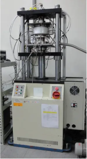
Fig.1.Apparatusfortheultrasonicvibration-assistedglasshotembossingprocess.
formingprocess.Second,theO-ringsealsbetweenthemovingdie andthevacuumchamberappliedanadditionalshrinkageforceon themovingdie.Becauseoftheseexternalforces,theapparatuswas unabletomonitortheappliedforcespreciselyenoughtoobtain aforcehistoryfor glassdeformation,resultingwitha compres-siontesterthatcouldnotadequatelyregulatetheembossingforce. Inaddition,theinfraredheaterswereinstalledinsidethevacuum chamber,wherethehighworkingtemperaturerenderedthem eas-ilybroken.InthedesignproposedbyFukuyama[10],theloadcell ishousedintheformingchamber,andthepressurefluctuationsin theformingchamberhavelittleeffectontheoutputoftheloadcell. Forthisstudy,anewapparatusforultrasonicvibration-assisted glasshotembossingwasbuilttoaddressthesedifficulties.Inthis design,theultrasonicvibratingdeviceisbuiltintotheupperdie. Inaddition,theloadcellislocatedinside thevacuumchamber toenhance the accuracyof force detection during theforming process.Twotypesofexperimentswereconductedwiththis appa-ratus.First, flathot embossing experiments wereperformedto investigatetheimpactofultrasonicvibrationonmoldingforces. Second,Fresnel structurehotembossingexperimentswere per-formedundera differentultrasonic frequencycompared tothe previousstudytoassessthemanufacturingpotentialofthe appa-ratusandtovalidatetheenhancedformabilitypossiblethroughthe useofultrasonicvibration.
2. Experimentalapparatus
Fig.1showsthenewhotembossingapparatusdevelopedfor thisstudy.Aheatingfurnaceandanultrasonicvibratingdeviceare
Table1
Specificationsofmoldingapparatusdevelopedforthisstudy.
Maximummoldtemperature 600◦C
Maximumvacuum 2×10⁻¹Torr
Displacementaccuracy 4m
Drivingresource Servomotor
Maximumload 50kN
Ultrasonicfrequency 35kHz±500Hz
Ultrasonicpower 900W
Ultrasonicvibrationamplitudeonboosterin25◦ 3m
attachedtoacompressiontester.Theheatingfurnaceheatsboth
themoldsandtheglassspecimensandprovidesavacuum
environ-mentfortheembossingprocess.Thecompressiontestercontrols
theembossingdisplacementwithfeedbacksignalsfromanoptical
encoderandaloadcell.Vibrationsareappliedtotheglass
speci-menbyanultrasonicvibratingdevicebuiltintotheupperdieof
thefurnace.Table1liststhespecificationsforthisapparatus.
2.1. Theheatingfurnace
Fig.2showsacross-sectionaldiagramoftheheatingfurnace.A quartztubeisintegratedintothevacuumchamberwall.In conjunc-tionwiththemovingflatbedofthecompressiontester,thelower diemovesinandoutofthisquartztubetoloadtheglass speci-men,embossit,andunloadtheproduct.Infraredheaterssurround thequartztubeoutsidethechamberwall,andtheinfraredlight penetratesthroughthequartztoheatthemoldsandthespecimen inside.
Thelowerdiecontainsaloadcell,whichiscooledbyalower coolertopreventfrombeingdamagedbythehighworking temper-aturesinthechamber.Theloadcell(LW-20100,Interface,Inc.)has acompensatedtemperaturerangeof16–71◦C,butbecauseits tem-peratureduringtheglasshotembossingprocessdoesnotexceed 35◦C, sensorcalibrationsforelevatedtemperaturesaredeemed unnecessary.Theloadcellisdonutshaped,withthecentral tun-nelaccommodatingthepipesforthewatercirculatinginthelower coolerandthevacuumpumpingforthechamber.Duringthe form-ingprocess,theloadcellisinsidethevacuumchamber.Theforce
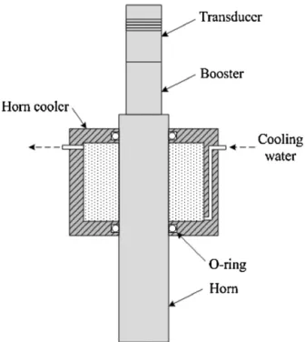
Fig.3.Designofhorncoolerforultrasonicvibratingdevice.
appliedcanthereforebedetectedfreeofexternalforces,enabling apreciseforcehistoryfortheformingglass.
Theinfraredheatersareplacedoutsidethevacuumchamberto increasetheirlifetimes.Aframewiththecirculatedcoolingwater supportssixheatersinasemi-circlethatsurroundsthechamber inthreelayers.Themaximumpoweroftheseheatersis7.8kW. Duringtheembossingprocess,thezoneinsidethequartztubeis pumpedtoformavacuum,andradiationfromtheheaterspasses throughthequartztubetothemoldsandglassspecimeninside thechamber.Theoutputpoweroftheheatersissuppliedbyan SCRandiscontrolledbyaUP150programtemperaturecontroller (YokogawaElectricCo.)thatreceivesfeedbacksignalsfroma K-typethermocoupleinstalledintothemold.
2.2. Ultrasonicvibratingdevice
Theultrasonicvibratingdeviceis designedtoworkproperly at35kHz.Thefrequencygenerator(KingUltrasonicCo.)issetto operatewithautomaticfrequencytrackingat35kHz±500Hz.For thermalprotection,ahorncoolerismountedoutsidetheultrasonic horn,asshowninFig.3.O-ringsplacedbetweentheultrasonichorn andthehorncoolertoformawatersealdonotsignificantlyaffect theabilityoftheultrasonicdevicetovibrate.
Theultrasonichornwasoriginallydesignedforuseatroom tem-peratureandhadadiameterof40mmandalengthof209mm.In theglasshotembossingprocess,however,thematerialproperties ofthehornareaffectedbythehighertemperatures,causingthe res-onantfrequencyofthevibratingdevicetoshiftbeyondthetracking rangeofthefrequencygenerator.Therefore,basedonthe compen-sationmethodproposedin[9],thelengthoftheultrasonichornwas reducedto202.5mm,andthemaximumworkingtemperatureof theultrasonicvibratingdevicewasraisedfrom150◦Cto450◦Cto accommodatethemoldingtemperaturesusedintheprocess.
3. Experiment 3.1. Procedure
Fig.4showstheexperimentalprocedure,whichprogressedas follows:(1) theglassandmoldsweresimultaneouslyheatedto themoldingtemperature(approximately20–40◦CaboveTg);(2) themold began embossing theglass at a preliminaryspeed of 0.1mm/mintoensurethatthetemperaturesonthecontact sur-faces of themolds and theglass were identical; (3) when the embossing displacement reached0.1mm,the embossing speed wasincreasedto1.5mm/min;(4)whentheembossing displace-mentreached1.5mm,ultrasonicvibrationwasapplied;(5)when theembossingdisplacementreached2mm,ultrasonicvibration ceasedandbothstageswereheldattheirfinalpositionsfor30s; and(6)theglasswasreleasedfromthemoldsandlefttocoolto roomtemperature.
K-PSK-100(SumitaOpticalGlass,Inc.)glasswith7mmin diam-eterand6.5mminheightwasusedinthisstudy.Accordingtothe manufacturer’sreport,theTgand theyieldingpoint(At)of the batchofglasswere398◦Cand426◦C,respectively.
3.2. Flathotembossing
Stainless AISI304 molds were used for theflat hot emboss-ingexperimentswiththemoldingsurfacespolished,asshownin Fig.5. Flatmolds wereusedin both theupperand lowerdies. Table2liststheexperimentalparameters,and Fig.6shows the force–displacementcurves. CurvesP1,P4, andP8 representthe resultsfortheconventionalglasshotembossingprocessatthree moldingtemperatures.Thedatashowthatwhenthemolding tem-perature was increased,less force wasrequired to emboss the glass.Whentheultrasonicvibrationwasapplied,therequiredforce droppedrapidlywhilethedisplacementcontinuedtoincrease.At thefinaldisplacementof2mm,anincreaseinforcereductionwas observedasthemoldingtemperaturedecreased.
Fig.5.Flatmold.
Table2
Parametersforflathotembossingexperiments.
No. Applyultrasonic vibration
Lowermold
temperature(◦C) Uppertemperaturemold(◦C)
P1 No 420 427 P2 Yes 420 428 P3 Yes 420 427 P4 No 425 432 P5 Yes 425 432 P6 Yes 425 433 P7 Yes 425 432 P8 No 430 435 P9 Yes 430 434 P10 Yes 430 434
Fig.6.Force–displacementresultsforflathotembossingexperiments.
Fig.8.Fresnelmold.
3.3. Fresnelstructurehotembossing
TheFresnelmoldswereformedbyelectroformingNiCoona
speciallydesignedFresnelstructure,whichwasmachinedby
ultra-precisionmachiningonNi.TheFresnelmoldswerecoatedwith
PtIrtopreventtheglassfromadheringtothemoldsduringthehot
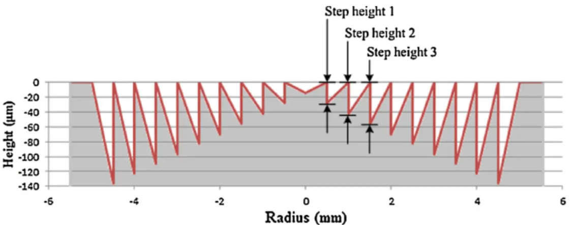
embossingprocess.Fig.7showsthedesigndimensionsandFig.8
showstheactualFresnelmold.InFig.7,severalstepheightsare defined,andthemeasurementsforthesestepheightsweretaken fromthemoldandthemoldedglassaftertheembossingprocess wascomplete.Inthehotembossingprocess,theFresnelmoldwas fixedtothelowerdie,andaflatmoldsimilartothatusedinthe flathotembossingexperimentwasmountedtotheupperdie.The moldingtemperatureswere431◦C and435◦Cintheupperand lowermolds,respectively.Fig.9showsanexampleofthemolded glass.
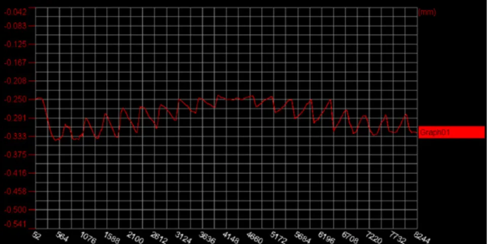
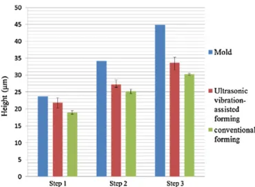
TheFresnelstructuresweremeasuredusinganapparatus con-sistingofaLK-H020laserdisplacementsensor(KEYENCECo.)and aservolinearactuator(ANIMATICSCo.),asshowninFig.10.Fig.11 showsthemeasurementresultsfortheFresnelmold,andFig.12 showsanexampleofthemeasurementsforthemoldedglass.Each pieceofmoldedglasswasscannedcross-directionally,sothatevery stepoftheFresnelstructureyieldedfourmeasuredvalues.Thestep heightswererecordedastheaverageofthesevalues.Fig.13shows thethreeinnerstepheightsofthemoldandthemoldedglass.These datashowsthattheheightsfortheultrasonicvibration-assisted hotembossingprocessarehigherthanthosefortheconventional processwithoutultrasonicvibration.
Fig.9.MoldedFresnelstructure.
4. Discussion
Theapparatusdevelopedforthisstudyovercamethedifficulty ofacquiringaccurateforcedatainavacuumenvironment,whichis criticalformonitoringproductqualityduringtheglasshot emboss-ingprocess.Thenewapparatuscanyieldprecisemeasurementsof theforcehistoryoftheglassduringformingandgenerateaccurate materialpropertiesofglass.Furthermore,thecompressiontester allowsforgreatercontroloftheappliedforcethaninearlierdesigns, andtherefore,productqualityisimproved.
Acoolingsystemisnecessarytopreventdamagetothe trans-ducercausedbythehightemperature,buttheadditionalmassof acoolerindirectcontactwiththeultrasonichornwoulddampen thevibrationsandchangetheresonantfrequencyoftheultrasonic
Fig.10.Apparatusforstructuralmeasurements.
vibratingdevice.Hence,thedesignedcoolerdoesnotcontactthe ultrasonichorndirectly,andO-ringsareadoptedtosealthe cool-ingwatersurroundingthehorn.Thissystemdeliverscoolingwater tothehornsurfacewithinsignificantchangesintheresonant fre-quency.
In the flat hot embossing experiments, ultrasonic vibration significantlyreducedtheforcerequired.Thismaybebecause ultra-sonicvibrationsraisedthelocaltemperaturebetweenthemolds and theglass,thussoftening theglass tothepointwhere flow conditions werecomparable tothoseobserved athigher mold-ingtemperaturesintheconventionalhotembossingprocess.With lowerrequiredmoldingtemperatures,heatingtimeisshortened,
Fig.11.MeasurementresultsfortheFresnelmold.
Fig.13.Measuredstepheightsofmoldandmoldedglass.
andefficiencyisimproved.Inaddition,embossingforcesare low-ered,reducingwearonthemoldsandextendingmoldlife.
IntheFresnelstructurehotembossingexperiments,ultrasonic vibrationenhancedthestepheightsofthemoldedFresnel struc-turesbyfurthersofteningtheglassandfacilitatingitsflowinginto themoldcavities.
5. Conclusion
Thisstudysuccessfullydemonstratedtheeffectivenessofanew apparatus designed for use in the ultrasonic vibration-assisted glasshotembossingprocess.A quartztubeisincorporatedinto thevacuumchamberwall.Infraredheaterssurroundthequartz tubeoutsidethechamber,andradiationfromtheheaterspenetrate throughthequartztubetoheatthemoldsandtheglassspecimen insidethechamber.The loadcellis insidethelowerdieand is protectedbyacoolingsystem.Becausetheloadcellisinsidethe vacuumchamberduringtheformingprocess,theeffectsof exter-nalforcesarenegligible;thus,theloadcellobtainsapreciseforce historyfortheformingglass.Theultrasonicvibratingdeviceisin
theupperdie,andacoolerprotectsthetransducerfromhigh tem-peratures.Anultrasonichornoriginallydesignedforuseatroom temperaturewasmodifiedtoensureproperfunctionatthehigh temperaturesrequiredbythehotembossingprocess.
Withthisapparatus,flathotembossingexperimentswere per-formedtoinvestigatetheeffectofultrasonicvibration.Theresult showthatformingforcesdroprapidlyasultrasonicvibrationis applied,thusindicatingthattheglassissoftened.Fresnelstructure hotembossingexperimentswerealsoconductedwiththesame apparatus,andthestepheightsofthemoldedglassstructureswere enhancedbyofultrasonicvibration.Theseresultsaretakento val-idatethemanufacturingpotentialofthedevelopedapparatusand confirmthatultrasonicvibrationimproveformabilityinglasshot embossing.
References
[1]Meden-PielingerGAA,VandeHeuvelJHP.Precisionpressedoptical
compo-nentsmadeofglassandglasssuitablemodeling,USPatent4,391,915(1983).
[2]TaniguchiY.Moldformoldingopticalelement.USPatent5,855,641(1999).
[3] FirestoneGC,JainA,YiAY.Precisionlaboratoryapparatusforhigh
temper-aturecompressionmoldingofglasslenses.ReviewofScientificInstruments
2005;76:063101,http://dx.doi.org/10.1063/1.1921367.
[4]Yi AY, Huang C, Klocke F, Brecher C, Pongs G, Winterschladen M,
et al. Development of a compression molding processfor three
dimen-sional tailored free-form glass optics. Applied Optics 2006;45:6511–8,
http://dx.doi.org/10.1364/AO.45.006511.
[5]SaotomeY.Microformabilityofopticalglassesforprecisionmolding.Journal
ofMaterialsProcessingTechnology2003;140:379–84.
[6] YiAY,ChenY,KlockeF,PongsG,DemmerA,GrewellD,etal.Ahighvolume
precisioncompressionmoldingprocessofglassdiffractiveopticsbyuseofa
micromachinedfusedsilicawafermoldandlowTgopticalglass.Journalof
MicromechanicsandMicroengineering2006;16:2000–5.
[7] MekaruM,NoguchiT,GotoH,TakahashiM.Effectofapplyingultrasonic
vibration in thermal nanoimprint lithography.Microsystem Technologies
2008;14:1325–33,http://dx.doi.org/10.1143/JJAP.46.6355.
[8] Lee CH, Jung PG, Lee SM, Park SH, Shin BS, Kim JH, et al.
Replica-tion of polyethylene nanomicro hierarchical structures using ultrasonic
forming.JournalofMicromechanicsandMicroengineering2010;20:035018,
http://dx.doi.org/10.1088/0960-1317/20/3/035018.
[9]TsaiYP,HungJC,YinLC,HungC.Ultrasonicvibration-assistedopticalglasshot
embossingprocess.InternationalJournalofAdvancedManufacturing
Technol-ogy2012;60:1207,http://dx.doi.org/10.1007/s00170-011-3669-8.
[10]FukuyamaS,FujiwaraS,SugiuraY.Pressformingmachineforglass.USPatent