非同步調變混合式鎖模光纖雷射之研究
65
0
0
全文
(2) 非同步調變混合式鎖模光纖雷射之研究 Study of hybrid mode-locked fiber laser by asynchronous modulation. 研究生:林倩伃. Student:Chien-Yu Lin. 指導教授:賴暎杰. 博士. Advisor:Dr. Y. Lai. 國立交通大學 電機資訊學院. 光電工程研究所. 碩士論文. A Thesis Submitted in Partial Fulfillment of the Requirements for the Degree of Master in The Institute of Electro-Optical Engineering College of Electrical Engineering and Computer Science National Chiao-Tung University Hsinchu, Taiwan, Republic of China. July 2005. 中華民國九十四年七月.
(3) 非同步調變混合式鎖模光纖雷射之研究. 研究生:林倩伃. 指導教授:賴暎杰. 博士. 國立交通大學光電工程研究所. 摘要. 在本論文中,我們利用非同步鎖模的技術在主被動混合式 鎖模摻鉺光纖雷射的架構中直接得到 10GHz 重複率飛秒級的 雷射脈衝光源,超模抑制比大於 70dB 且平均功率大於 30mW。 由我們的實驗結果可發現非同步調變能夠提供一個相當簡單 而有效的方式來穩定混合式鎖模光固子光纖雷射,我們另外也 提出一種新的方法來針對非同步鎖模雷射進行共振腔長補償 以達到長時間的穩定操作。. i.
(4) Study of hybrid mode-locked fiber laser by asynchronous modulation Student:Chien-Yu Lin. Advisor:Dr. Y. Lai. Institute of Electro-optical Engineering College of Electrical Engineering and Computer Science National Chiao-Tung University. Abstract. In the thesis, by employing the technique of asynchronous mode-locking(ASM), direct generation of femtosecond pulse train at 10GHz repetition rate with the super-mode-suppression-ratio(SMSR)above 70dB and with the output average power larger than 30mW is demonstrated in a hybrid mode-locked Er-fiber laser. Our experimental results show that asynchronous mode-locking can provide one simple and effective mechanism to stabilize hybrid mode-locked soliton fiber lasers. New method of dithering the cavity length to achieve the long-term stabilization for asynchronous mode-locked fiber lasers is also proposed and investigated.. ii.
(5) 致謝. 轉眼間短暫的碩士班即將結束了!很喜歡在光電所的時光,在這 裡我除了有機會訓練自己的實驗能力與研究態度之外,也結交了很多 好朋友,豐富了我這兩年的生活。首先感謝賴暎杰老師不厭其煩的指 導我的論文,在我感到困惑時為我指點迷津,另外老師寬大圓融的處 世態度及努力不懈的求知精神也都很值得我去學習。感謝祁甡老師、 陳智弘老師與馮開明老師撥冗擔任口試委員並提出寶貴精闢的指 教,使本論文更加完善。 另外感謝實驗室項維巍學長、李瑞光學長與徐桂珠學姊在實驗與 生活上的幫忙,以及祁老師實驗室的學長姐們在實驗儀器設備上的商 借與專業的討論,幫助我解決了不少困難;也要感謝實驗夥伴淑惠、 玉婷、金水、銘峰、銘清等以及陳老師與馮老師實驗室的同學們這些 日子來的相處與砥礪,有你們的陪伴我的研究生活增添了不少色彩。 最後將這篇論文獻給在背後默默支持我的父母,謝謝你們對我無 悔的付出與栽培,僅以此篇論文與你們分享我的喜悅之情。. 2005.7.15 風城交大. iii.
(6) Contents Chinese abstract English abstract Acknowledgement Contents Diagram contents Chapter 1:Introduction………………………………………………1 1.1 Preface…………………………………………………………...1 1.2 History of fiber laser……………………………………………..2 1.3 Motivation………………………………………………………..3 1.4 Outline of the thesis……………………………………………...4 Chapter 2:Principles of mode-locked lasers…………………………..5 2.1 Active mode-locked lasers……………………………...………..6 2.1-1 Amplitude modulation…………………………………………………6 2.1-2 Phase modulation………………………………………………………8 2.1-3 Noise sources of active mode-locking……………………...………...10. 2.2 Passive mode-locked lasers…………………………………….14 2.2-1 Saturable absorbers…………………………………………………...14 2.2-2 Nonlinear amplifying loop mirror………………………...…………..16 2.2-3 Polarization additive pulse mode-locking…………………..………...17. 2.3 Hybrid mode-locked lasers……………………………………..19 2.4 Asynchronous mode-locked lasers……………………………..20 Chapter 3:Experimental setup and results…………………………24 3.1 Results of mode-locking……………………………..................24 iv.
(7) 3.1-1 Configuration and parameters………………………………………...24 3.1-2 Results of normal active mode-locking………………………………26 3.1-3 Results of synchronous hybrid mode-locking………………………...29 3.1-4 Results of asynchronous hybrid mode-locking……………………….32 3.1-5 State of bound soliton pulse…………………………………………..36 3.1-6 Summary……………………………………………………………...40. 3.2 Stabilization of asynchronous hybrid mode-locking…………...41 3.2-1 Introduction…………………………………………………………...41 3.2-2 Configuration and parameters………………………………………...42 3.2-3 Results………………………………………………………………...47. 3.3 Discussions……………………………………………………...49 Chapter 4:Conclusions and future work……………………………50 4.1 Summary of achieved results……………………………………50 4.2 Future work……………………………………………………..52 References……………………………………...……………………….53. v.
(8) Diagram Contents. Fig 2-1. Pulse train formed when several modes of equal amplitudes are mode-locked……………………………………………………………...5. Fig 2-2. Description in the frequency domain for AM mode-locking……………..6. Fig 2-3. Principle of AM mode-locking in time domain…………………………..7. Fig 2-4. Schematic of synchronized different modes……………………………...8. Fig 2-5. Principle of PM mode-locking in time domain…………………………..9. Fig 2-6. Superession of supermodes by Fabry-Perot filter……………………….11. Fig 2-7. Intensity dependent transmission produced by nonlinear polarization rotation…………………………………………………….12. Fig 2-8. Configuration of harmonically and regeneratively mode-locked Er-fiber ring laser……………………………………………………….13. Fig 2-9. Schematic of passively mode-locking with saturable absorber…………14. Fig 2-10. Diagram of the time dependent pulse and net gain with fast saturable absorber……………………………………………………….15. Fig 2-11. Diagram of the time dependent pulse and net gain with slow saturable absorber……………………………………………………….16. Fig 2-12. Principle of operation of the NALM operated in reflection…………….17. Fig 2-13. Diagram of how pulse shortening occurs in a laser through P-APM…...18. Fig 2-14. Steady-state time deviation of a detuned soliton………………………..23. Table 3-1 Devices in the fiber ring cavity…………………………..……………...25 Fig 3-1. Eexperimental setup…………………………………………………….26. Fig 3-2. Optical spectrum of normal active mode-locking at 10GHz repetition rate 27. Fig 3-3. RF spectrum of normal active mode-locking at 10GHz………………….28 vi.
(9) Fig 3-4. The SHG autocorrelation of the pulse at 10GHz under normal active mode-locking……………………………………………………...28. Fig 3-5. Optical spectrum at synchronous modulation…………………………….30. Fig 3-6. RF spectrum at synchronous modulation(center 10GHz, span 50MHz)30. Fig 3-7. RF spectrum near 10GHz at synchronous modulation…………………...31. Fig 3-8. The SHG autocorrelation of the pulse at 10GHz under hybrid mode-locking by synchronous modulation………………………………31. Fig 3-9. Optical spectrum at asynchronous modulation…………………………...33. Fig 3-10. The SHG autocorrelation of the pulse at 10GHz under hybrid mode-locking by synchronous modulation……………………….34. Fig 3-11. RF spectrum from 0Hz to 40GHz at synchronous modulation…………..34. Fig 3-12 RF spectrum at asynchronous modulation(center 10GHz, span 50MHz)35 Fig 3-13. RF spectrum near 10GHz at synchronous modulation…………………...35. Fig 3-14. Formation of pulse splitting………………………………………………36. Fig 3-15 Optical spectrum of bound soliton pulse…………………………………37 Fig 3-16 Autocorrelation of bound soliton pulses…………….…............................38 Fig 3-17. RF spectrum of bound soliton pulses at 10GHz(center 10GHz, span 50MHz)…………………………………………………………………..39. Fig 3-18. RF spectrum of bound soliton pulses near 10GHz(span 500kHz)……..39. Fig 3-19. The experimental setup of stabilization…………………………………..44. Fig 3-20. The picture of handmade PZT stretcher………………………………….45. Fig 3-21. Relation between the input voltage applied on PZT and the obtained frequency shifts…………………………………………………………..45. Fig 3-22. Spectral components of detuning frequency near DC……………………46. Fig 3-23 Diagram of the feedback circuit………………...………………………..46 Fig 3-24. Changes in the detuning frequency near DC with time………………….48 vii.
(10) Fig 3-25. Stabilization of initial 100 seconds………………………………………48. Fig 3-26. Changes in the repetition rate of regeneratively mode-locking………….49. viii.
(11) Chapter 1:Introduction 1.1 Preface One of the most significant technological breakthroughs in data transmission has been the development of practical fiber optic communications systems. Optical fiber already enjoys considerable use in long-distance telecommunications because of its distinguishing characteristics such as greater capacity, smaller size and lighter weight, lower attenuation, electromagnetic isolation and greater repeater spacing. The continuing improvements in performance and decline in prices, together with the inherent advantages of optical fiber, have made it increasingly attractive for metro and local area networking. Particularly after 1986 when the techniques for the fabrication of low-loss, rare-earth-doped fibers were perfected to make fiber amplifiers, the design of fiber-optic communication systems was revolutionized [1]. Such fiber amplifiers commonly used to overcome transmission losses encountered by the signal in the optical domain and permit propagation of lightwave signals over thousands of kilometers. At the same time, fiber amplifiers enable the use of massive wavelength-division multiplexing (WDM) and have led to the development of lightwave systems with capacities exceeding 1Tb/s [2]. The nonlinearity of optical fibers also plays an increasingly important role in the design of such high-capacity lightwave systems [3]. Among many kinds of optical amplifiers, EDFAs have attracted. 1.
(12) the most attention as they operate near 1.55μm and are useful for modern fiber-optic communication systems [4]. By being placed inside a cavity designed to provide optical feedback, the fiber amplifier also can be converted into a laser which is called fiber lasers. Fiber laser research is one of the most recent major activity in the research of glass lasers. They offer promise for finding important applications in telecommunication and sensing .. 1.2 History of fiber laser The first fiber lasers was based on trivalent neodymium in an alkali—alkaline earth silicate, which emitted lights at 1.06μm. The next development was the CW fiber laser demonstrated in 1973 [5]. However it was not until the publication twelve years later by Mears et al. that widespread activity in fiber lasers began, including the extension of the host from fused silica to heavy mental fluorides as well as the investigation of many other rare-earth transitions. A method of locking the multiple axial modes in a laser cavity is called mode-locking. It can also be used mode-locked fiber lasers in which the rare-earth-doped fibers are acting as the gain medium. Mode-locked fiber lasers can be made very long, up to several kilometers, which allows for low repetition rates. Several groups have reported mode locking of neodymium-doped and erbium-doped fiber lasers.. 2.
(13) Geister and Ulrich built the first integrated system using a lithium niobate phase modulator and obtained 90ps pulses at 1080nm [5]. Up to date, the shortest pulse width obtained from a mode-locked fiber laser was shorter than 100fs.. 1.3 Motivation Mode-locked fiber lasers have been demonstrated to be able to generate pulse trains with a high repetition rate. By using the technique of harmonic mode-locking, a few tens of GHz repetition rate can be achieved in actively mode-locked fiber lasers. However, the pulse-width from actively mode-locked lasers is typically several picoseconds. Therefore, additional pulse compression mechanisms outside or inside the laser cavity are needed to obtain shorter pulse-width. Recently, hybrid mode-locking provides one alternative method to directly generate femtosecond pulses at the high repetition rate. Besides the active mode-locking, the mechanism of passive mode-locking is also included in these hybrid mode-locked fiber lasers. Hopefully pulse trains with femtosecond pulse-width at several GHz repetition rate can be directly generated from the output of the mode-locked fiber laser. No matter in the case of active mode-locking with the extra compression mechanisms or in the case of hybrid mode-locking, feedback control of the laser cavity is required to stabilize the fiber laser for long term due to the long cavity length of several tens of. 3.
(14) meters. In addition, one interesting but less studied mode-locking mechanism is the asynchronous modulation hybrid soliton mode-locking technique [6], in which the laser noises can be suppressed by the asynchronous modulation along with the nonlinear soliton effects. The main objective of this thesis study is thus to actually build asynchronous hybrid mode-locked Er-fiber lasers for studying their properties.. 1.4 Outline of the thesis The structure of the thesis is as below: Chapter 1 gives an introduction about the fiber lasers and explains our motivation of research. In the second chapter the theory of mode-locked fiber lasers including active mode-locking, passive mode-locking, hybrid mode-locking and asynchronous mode-locking are presented. Chapter 3 demonstrates the experimental setup and results. In the final chapter we make a brief conclusion and discuss possible future work.. 4.
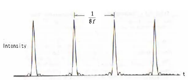
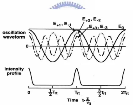
(15) Chapter 2:Principles of mode-locked lasers Mode-locking of a fiber laser is interesting for short pulse generation that is compatible with communication and fiber sensor systems. The simplest fiber laser consists of an amplifying medium located between two mirrors forming the resonator. The mode-locking action is attained by coupling together the longitudinal modes of a laser which are equally separated by the intermodal frequency ∆f =. c (where l is the 2l. optical length between two mirrors and c is the speed of light)and locking their phases to each other. When the phases of these components are locked together, they behave like the Fourier components of a periodic function, and therefore form a periodic pulse train [7]. Experimentally this can be achieved in a variety of ways including active and passive methods.. 1 ∆f. Fig 2-1 Pulse train formed when several modes of equal amplitudes are mode-locked. 5.
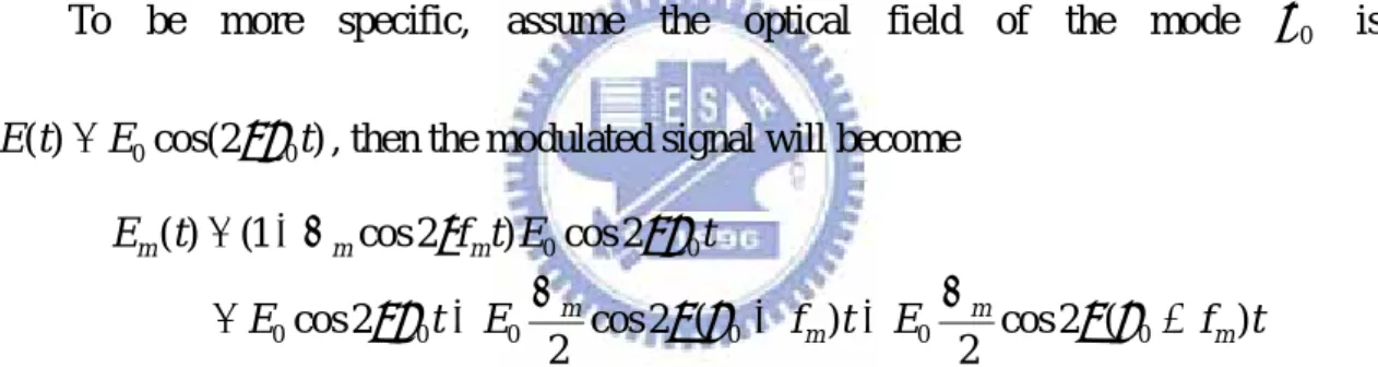
(16) 2.1 Active mode-locked lasers 2.1-1 Amplitude modulation(AM) The basic concept of amplitude modulation can be understood with either time-domain or frequency-domain arguments. If a mode exists with its frequency ν 0 at the peak of the gain curve and if it propagates through a amplitude modulator operating at a frequency f m , sidebands are generated at frequencies given by ν 0 ± f m . If f m matches the mode spacing of the cavity ∆f , the modes adjacent to the lasing mode will be coupled together with a well-defined phase and amplitude relationship. To be more specific, assume the optical field of the mode ν 0. is. E (t ) = E 0 cos(2πν 0 t ) , then the modulated signal will become E m (t ) = (1 + ∆ m cos 2πf m t ) E 0 cos 2πν 0 t = E 0 cos 2πν 0 t + E 0. ∆m ∆ cos 2π (ν 0 + f m )t + E 0 m cos 2π (ν 0 − f m )t 2 2. where ∆ m is the amplitude modulation index. This expression explains the generation of side frequencies through amplitude modulation.. Fig 2-2 Description in the frequency domain for AM mode-locking. 6.
(17) Alternatively, in the time domain, when the modulation period is matched to the cavity round-trip time, the light which is incident at one particular point in the modulation cycle will be incident at the same point after one round trip of the cavity. Thus any light that suffered a loss after one round trip will always experience a loss. All the lights in the cavity will experience a net loss except those which pass through the modulator around the zero loss point.. Fig 2-3 Principle of AM mode-locking in time domain. 7.
(18) 2.1-2 Phase modulation(PM) An alternative way to induce the necessary coupling between the modes is to use an electro-optic phase modulator. It is similar to the amplitude modulation, except that it changes the optical phase instead. The modulated optical signal can be written as: E m (t ) = E 0 cos(2πν 0 t + ∆ m cos 2πf m t ) ∞. = E 0 ∑ J n (∆ m ) cos(2πν 0 t + 2πnf m t ) −∞. where ∆ m is the phase modulation index and J n is the n-th order Bessel function. It can be seen that the modulated optical signal is composed of infinite side frequencies n ⋅ fm .. Fig 2-4 Because the phases of different modes are synchronized, the modes can combine together to form a short pulse train.. 8.
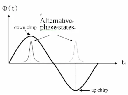
(19) Fig 2-5 Principle of PM mode-locking in time domain. Fig 2-5 describes the periodic phase modulation of the modulator. When the light passes through a phase modulator it experiences a frequency shift which is proportional to the rate of phase change with respect to time(if. dφ ≠ 0 ), unless it passes through the dt. modulator at an extremum of the phase modulation cycle(. dφ = 0 ). At either of these dt. two points no frequency shift is induced upon the light. Successive transits through the modulator result in a shifting of the light outside of the gain bandwidth of the active medium, thus inducing a loss for that light. However, around the two points in the modulation cycle where. dφ = 0 , the lights experience no frequency shift and will be dt. amplified continuously in the cavity. This leads to the production of a pulse train inside the laser. Which point is stable is dependent on the sign of the cavity dispersion.. 9.
(20) 2.1-3 Noise sources of active mode-locking Generally speaking, the cavity length will not be too short(about several tens to hundred meters)for mode-locked fiber lasers, and the cavity fundamental frequency is in the MHz order. Therefore there are some problems in the operation of actively harmonic mode-locked fiber laser as explained below [8]: 1. Because the longer cavity length will be affected by environmental vibration and temperature perturbation easily, the fundamental frequency is not stable. It will result in difference between the modulation frequency and pulse repetition rate and degrade the mode-locking effect. 2. The fiber lasers have to be operated at the harmonic mode-locking region to achieve pulse trains with a higher repetition rate. It will result in the extra supermode noises and cause the unequal energy distribution, pulse dropout and power fluctuations of the output pulses. 3. Because the slow gain relaxation time cannot equalize the individual pulse energy, harmonically mode-locked fiber lasers suffer from supermode noises.. Therefore we need additional stabilization mechanisms to solve these problems and the following methods have been studied in the literature:. 10.
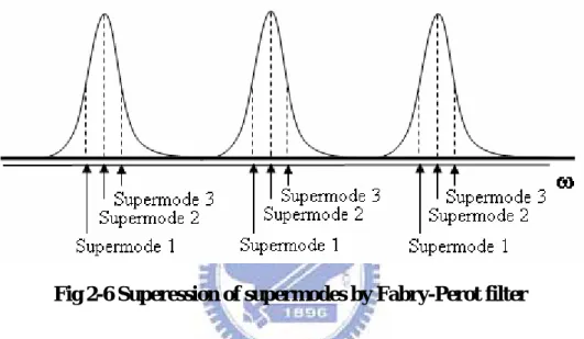
(21) A. Fabry-Perot etalon [9] By adding a Fabry-Perot filter in the cavity and adjusting the separation, the free spectral range of the etalon can be set to match the harmonic frequency Nf 0 . Thus there will exist only one supermode in the cavity. As in Fig 2-6, only the supermode 2 has less loss and can survive.. Supermode 1. Fig 2-6 Superession of supermodes by Fabry-Perot filter. B. Self-phase modulation(SPM)cooperating with optical band-pass filter [10] When the peak power of the pulse in a long cavity increases, SPM can become important and the wing of the pulse is frequency chirped. The energy at the pulse center shifts to the wings and is eliminated by the filter. Hence the pulse amplitude is clipped to a certain intensity level at which the pulse energy is stabilized. This process acts as an intensity-dependent gain limit. C. Additive-pulse limiting(APL)[11] APL utilizes the principle of additive-pulse mode-locking(APM)by using the nonlinear polarization rotation effect in a fiber laser but with a different bias point. When the laser 11.
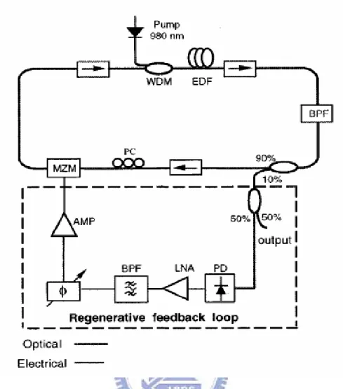
(22) is biased in the APL regime, higher intensity pulses experience greater loss, so the laser pulse intensity fluctuations can be minimized. As a result, the laser will oscillate with pulses of equal energy in every modulator transmission window. APL suppresses pulse-to-pulse amplitude fluctuations in harmonically mode-locked lasers.. Fig 2-7 Intensity dependent transmission produced by nonlinear polarization rotation. D. Regenerative mode-locking [12] Regenerative mode-locking is accomplished by feeding back the self-beating signal of the output pulse train which is detected with a high speed photodetector and filtered by a high Q filter. The phase between the pulse train inside the cavity and the modulation signal is automatically adjusted so that the pulses will always experience maxium transmission when they pass through the modulator. In this way the mode-locking can be maintained automatically because the ideal feedback signal will reflect the instantaneous frequency change between the longitudinal beats.. 12.
(23) Fig 2-8 Configuration of harmonically and regeneratively mode-locked Er-fiber ring laser. E. Semiconductor optical amplifier(SOA)[13] The fast saturable gain of the SOA can act as a saturable absorber to stabilize the laser intensity noises. In the time domain when the following pulse with more energy passes through the SOA, it will get lower gain due to the gain saturation effect. On the contrary, the following pulse with less energy will get higher gain. Thus the amplitude fluctuations of the pulse train can be reduced.. 13.
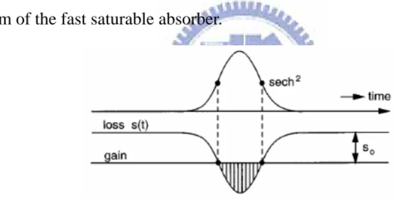
(24) 2.2 Passive mode-locked lasers Passive mode locking utilizes all-optical nonlinear techniques and is capable of generating ultrashort optical pulses without any active component(such as a modulator) inside the laser cavity. In these lasers the modulation effect is produced by the mode-locked laser pulse itself, which means that the modulation always remains in perfect synchronism with the circulating pulse. In general the technique makes use of a nonlinear device whose response to an entering optical pulse is intensity dependent such that the exiting pulse is narrower than the input pulse. The modulation effect can become both stronger and faster as the pulse itself becomes shorter.. 2.2-1 Saturable absorbers The basic mechanism in nearly all the passive mode-locked lasers is the pulse shortening effect caused by the transmission through a saturable absorber element.. Fig 2-9 Schematic of passively mode-locking with saturable absorber. The change in pulse shape on passing through the absorber will then depend quite strongly on whether the absorbing medium is a fast saturable or a slow saturable 14.
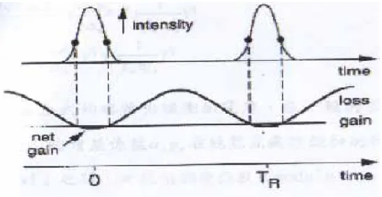
(25) absorber. The absorption recovery time is much shorter than the pulse width for the fast saturable absorber. On the contrary, the recovery time of the slow saturable absorber is much longer than the pulse width. Considering a fast saturable absorber which can respond immediately, the laser gain is approximately time independent and the net gain window is fully dependent on the input optical pulse width. When an optical pulse propagates through such an absorber, its wings experience more loss than the central part which is intense enough to saturate the absorber. This will lead to the pulse shortening during its passage through the absorber. Fig 2-10 shows the physical mechanism of the fast saturable absorber.. Fig 2-10 Diagram of the time dependent pulse and net gain with fast saturable absorber. When the recovery time is much longer than the pulse width, the absorber cannot respond immediately to recover to the initial loss within the duration of the optical input pulse. Thus by combining with the dynamic laser gain, the pulse shortening effect is still possible. Fig 2-11 shows the physical mechanism of the slow saturable absorber.. 15.
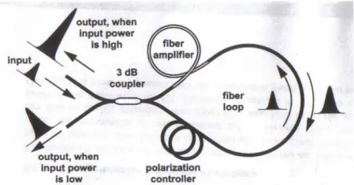
(26) Fig 2-11 Diagram of the time dependent pulse and net gain with slow saturable absorber. 2.2-2 Nonlinear amplifying loop mirror(NALM) The NALM consists of a fiber Sagnac ring with gain placed asymmetrically in the loop [14]. A differential phase shift occurs between the two directions in the NALM, and with proper phase bias the NALM transmits higher intensities while reflecting low intensities. The NALM is attached to a unidirectional fiber ring, forming a figure-8 shaped cavity where the reflected low intensities are then extinguished by the isolator in the unidirectional ring. As the Fig 2-12 shows, when the pulse energy is increased, self-phase modulation will cause an imbalance for the two counterdirectional pulses inside the loop. The reflectivity of the NALM thus becomes power-dependent and can act as an all-optical switch to produce femtosecond pulses.. 16.
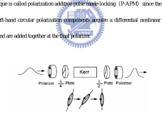
(27) Fig 2-12 Principle of operation of the NALM operated in reflection. 2.2-3 Polarization additive pulse mode-locking(PAPM) Additive pulse mode-locking(APM)is a passive mode-locking technique that employs a nonlinear interferometer to achieve pulse shortening [15]. The pulse is split into the two arms of the interferometer with a nonlinear element placed in one arm. The pulses recombine at the beam splitter, and pulse shortening occurs through the coherent addition of the self-phase modulated pulses. One advantage of APM is that it is extremely fast because it is based on self-phase modulation(SPM)from the Kerr effect in glass. Thus APM should not impose a practical limit on the shortest pulses and has been extended to fiber lasers, where pulse shortening is achieved through SPM and polarization control. Nonlinear polarization rotation can occur in an optical fiber when the initial polarization state is elliptical. The ellipse can be resolved into right- and left-hand. 17.
(28) circular polarization components of different intensities. These two circular components then accumulate different nonlinear phase shifts related to the intensity dependence of the refractive index( n = n 0 + n 2 I ). The polarization ellipse rotates while maintaining its ellipticity and handness. An optical fiber is particularly well suited for nonlinear polarization rotation because the small mode diameter leads to high intensities, and thus to a large nonlinear index change, and also because long fiber lengths can be used. The nonlinear polarization rotation can also be used in conjunction with bulk polarization optics to obtain an artificial saturable absorber for mode-locking. The mode-locking technique is called polarization additive pulse mode-locking(P-APM)since the rightand left-hand circular polarization components acquire a differential nonlinear phase shift and are added together at the final polarizer.. Fig 2-13 Diagram of how pulse shortening occurs in a laser through P-APM. 18.
(29) 2.3 Hybrid mode-locked lasers Hybrid mode-locking combines multiple mode-locking techniques within the same laser cavity to improve the laser performance [16]. The most obvious combination incorporates an amplitude or phase modulator inside a passively mode-locked fiber laser. As early as 1991, the active and passive mode-locking techniques were combined by using a phase modulator. Then this combination has led to considerable improvement of mode-locked lasers. The modulator provides periodic timing slots to produce a pulse train with high repetition rate while the passive mode-locking mechanism shortens the pulse to a level that cannot be expected from active mode-locking alone. An alternative hybrid mode-locking method is to add a real slow saturable absorber in a cavity using a fast saturable absorber. The slow saturable absorber can easily produce a several picoseconds pulse to be helpful for initiating mode-locking(self-starting capability) [17].. 19.
(30) 2.4 Asynchronous mode-locking The active, synchronous mode-locking using a modulator combined with negative group-velocity dispersion(GVD)and self-phase modulation(SPM)is able to produce soliton-like pulses as long as the anomalous GVD and SPM are strong enough. However as the pulse is shortened, it becomes increasingly difficult to maintain pulse timing which in turn requires cavity and modulator stabilization. To stabilize the mode-locked soliton lasers, an approach using a phase modulator which is purposely detuned from a cavity harmonic has been proposed. This is called the asynchronous modulation method. Because the modulation frequency and cavity harmonic frequency are not the same, asynchronous phase modulation will produce a sinusoidal frequency shift through the phase modulator. The frequency shifts combine with the cavity dispersion can cause the sweeping of the pulse. The continuum noises will be frequency-shifted and experience larger loss while the solitons are able to resist the frequency shift and remain intact. The master equation for a phase modulated mode-locked ring laser with GVD and SPM can be written as [18]:. TR. ⎫⎪ ⎛ g ⎞ d2 ∂A ⎧⎪ 2 = ⎨( g − l ) + ⎜ 2 + jD ⎟ 2 + jδ A + jM cos[Ω M t + Ω M ∆T (T )]⎬ A + N (T ) ⎜Ω ⎟ dt ∂T ⎪⎩ ⎪⎭ ⎝ g ⎠. where TR :the roundtrip cavity time. g :the saturated gain per pass l :the loss, Ω g is the gain bandwidth 20.
(31) D :the group velocity dispersion parameter. δ :the Kerr coefficient M :the depth of phase modulation Ω M :the modulation frequency N (T ) :the spontaneous emission white noise. Under synchronous modulation the cosine function can be approximated by a parabolic function and the noise can be expanded in a basis of Hermite Gaussian functions without the nonlinearity and the noise source terms. Anoise = A0 H ν (ξ )e. ξ2 2. If only the lowest order mode, which has the lowest decay rate and thus is the most critical one, is considered, then the required net gain is. (g − l )noise. ⎞ MΩ 2M ⎛ g = Re ⎜ 2 + jD ⎟ j ⎟ ⎜Ω 2 ⎠ ⎝ g. In addition to the noises, solitons also circulate in the ring and the soliton pulse shape is ⎛ t Asoliton (t ) = A0 sec h⎜⎜ ⎝τ s. ⎞ ⎟⎟ ⎠. A soliton suffers approximately the same loss under synchronous and asynchronous modulation. Thus the required net gain to compensate for the filtering loss in both cases is. (g − l )soliton. 21. =. 2g 3Ω 2gτ s2.
(32) Therefore, the noise will decay relative to the solitons if the required gain is higher. The preceding analysis is under the condition that the noise decay rate is much faster than the detuning rate. Hence the solitons remain stable over the noises if. ∆f <<. ⎞ MΩ 2M ⎛ g 1 Re ⎜ 2 + jD ⎟ j ⎟ ⎜Ω TR 2 ⎠ ⎝ g. The noise is frequency shifted by the asynchronous modulator into the wings of the filter, which results in higher loss for the noises. On the other hand, solitons resist the frequency shift because of their nonlinearity. The width of the soliton spectrum is proportional to the soliton energy. The loss rate due to filtering in turn is proportional to the spectral width and thus is proportional to the soliton energy. In other words, the loss rate is proportional to the bandwidth of the soliton. Therefore, each soliton acquires an energy determined by the filtering loss without the need for additional stabilization. However, under asynchronous modulation, there exist sinusoidal variation of the carrier frequency and the corresponding position shift in the time domain, as shown in Fig 2-14. The phenomena can be explained by the soliton perturbation theory.. 22.
(33) Fig 2-14 Steady-state time deviation of a detuned soliton. Although the frequency deviation between the modulation frequency and cavity harmonic frequency is necessary, there still exists detuning limits. When the detuning exceeds this upper limit, the noise cleanup mechanism achieved through accumulated frequency shifts is diminished. Besides, the modulation must periodically cycle into synchronism, thereby refreshing the timing of the pulses. A lower limit of the detuning rate is required to enforce pulse timing.. 23.
(34) Chapter 3:Experimental setup and results 3.1 Results of mode-locking 3.1-1 Configuration and parameters In our experiment, the technique of hybrid mode-locking is used. We put an EO modulator into the cavity of a passively mode-locked laser and keep the setup all-fiber. The additive-polarization mode-locking and the EO phase modulation are combined together to achieve the hybrid mode-locking, as shown in Fig 3-1 [19]. In order to get more nonlinearity in the fiber cavity, high intracavity light intensity is needed. As a result, the method of bi-directional pumping is utilized in the experimental setup and about 750mW of 980nm pump is available in the experiment. An EO phase modulator is put in the fiber ring cavity to achieve active mode-locking, and the polarization dependent EO modulator and two polarization controllers provide the mechanism of additive-pulse mode-locking. Because the EO phase modulator in the fiber ring cavity is polarization dependent, it also works as a polarizer. If the EO modulator is replaced with a polarization dependent isolator, the laser becomes a purely passively mode-locked laser. The isolator in the ring cavity is to ensure the pulses propagate in only one direction. The tunable bandpass filter, whose specifications are shown in Fig 3-2, is used to select the lasing wavelength of the laser. In addition, it can cooperate with the. 24.
(35) self-phase modulation(SPM)effect in the cavity to suppress supermodes and to achieve a high supermode suppression ratio(SMSR). Besides, the 14nm wide bandwidth of the bandpass filter can support shorter pulses in the cavity so that the generated pulse width also can be shorter. The output coupler is put behind the Er-fiber to get the greatest output power. The coupling ratio is 30/70 to couple 30% power inside the laser to the laser output. The chirp of the pulses is compensated with a length of negative group-velocity dispersion (GVD)fiber.. Our laser can be operated at different states, including the normal active mode-locking, hybrid mode-locking with synchronous and asynchronous modulation. The devices that have been used in the fiber ring cavity are listed in table 3-1.. 1. 980nm pump laser:maximum output power:500mWx1;350mWx1 2. EO phase modulator(from D.C. to 10GHz) 3.. Tunable. bandpass. filter : 3dB. bandwidth. Æ. wavelengthÆ1540~1560nm 4. WDM coupler 5. Polarization independent isolator 6. Corning SMF-28:about 8m 7. Corning Flexcor fiber:about 5.5m 8. PM panda fiber:located at the EO phase modulator about 4m Table 3-1 Devices in the fiber ring cavity 25. 14nm;. central.
(36) Fig 3-1 Experimental setup. 3.1-2 Results of normal active mode-locking Our laser is able to work at the state of active mode-locking. The passive mode-locking mechanism is reduced to be very small and the laser now is like a normal active mode-locked laser with little accumulation of the nonlinearity and the pulse width also become larger. The optical spectrum at the normal active mode-locking is shown in Fig 3-2 and the RF spectrum is shown in Fig 3-3. In Fig 3-4 the pulse width from SHG autocorrelation is 4.7ps and the time-bandwidth product is 0.43. In addition,. 26.
(37) the supermode suppression ratio(SMSR)is about 50dB.. Fig 3-2 Optical spectrum of normal active mode-locking at 10GHz repetition rate. 27.
(38) -20. -40. -60. -80. -100 0. 10G. 20G. 30G. 40G. Frequency(Hz). Fig 3-3 RF spectrum of normal active mode-locking at 10GHz. 10GHz repetition rate FWHM=4.7ps(Gaussian fitting) 4. 2. 0. 8. 6. 4. 2. 0 0. 5000. 10000. 15000. 20000. 25000. Delay Time(fs). Fig 3-4 The SHG autocorrelation of the pulse at 10GHz under normal active mode-locking 28.
(39) 3.1-3 Results of synchronous hybrid mode-locking If the modulation frequency and the cavity harmonic frequency are the same then the laser is mode-locked by synchronous modulation. The cavity length is about 24m, and the net dispersion of the cavity is about 1.77ps/nm-km. The pulses in the fiber ring cavity are under abnormal dispersion so that the solitons are able to be generated. But in the synchronous condition, the solitons do not occur. One of the reasons may be that the power in the cavity is not enough for the pulses to accumulate large nonlinearity. The other reason may be that the loss for the soliton is larger than that for the Gaussian pulses so that the Gaussian pulse train is produced and the solitons are suppressed. The optical spectral bandwidth of the output pulses is 1.74nm, shown in Fig 3-5, and the transform-limited pulse width is 1.5ps. This pulse width is still narrower than that produced by the purely active mode-locked lasers. This is because there is still some nonlinearity in the cavity. The output power is 28.6mW and the corresponding peak power is 1.87W. The RF spectrum is shown in Fig 3-6, and the SMSR is about 50dB. Fig 3-7 shows the details of the RF spectrum at 10GHz. The parameters of the mode-locked laser at 10GHz repetition rate are listed in Table 3.1. The autocorrelation of the pulse is shown in Fig 3-8.. 29.
(40) Fig 3-5 Optical spectrum at synchronous modulation. 0 -20. 50dB. -40 -60 -80 -100 9.98G. 9.99G. 10.00G. 10.01G. 10.02G. Frequency(GHz). Fig 3-6 RF spectrum at synchronous modulation(center 10GHz, span 50MHz). 30.
(41) 0 -20 -40 -60 -80 -100 9.9979G 9.9980G 9.9981G 9.9982G 9.9983G. Frequency(GHz). Fig 3-7 RF spectrum near 10GHz at synchronous modulation. 1 0 G re p e titio n ra te F W H M = 1 5 2 7 fs (se ch ^2 fittin g ). 0. 8. 6. 4. 2. 0. 0. 5 0 00. 1 00 00. 1 5 00 0. 20 00 0. 2 50 00. D e la y tim e (fs). Fig 3-8 The SHG autocorrelation of the pulse at 10GHz under hybrid mode-locking by synchronous modulation 31. 3 0 00 0.
(42) 3.1-4 Results of asynchronous hybrid mode-locking If the modulation frequency and the cavity harmonic frequency are not the same (with 20~40kHz deviation), then the fiber laser is mode-locked by asynchronous. modulation. The method for achieving asynchronous mode-locking is to find the mode frequency precisely first and adjust the frequency of the synthesizer to be 20~40kHz away from the frequency found before. Then we adjust the polarization controllers properly to achieve mode-locking. In this way, whether the modulation frequency is little larger or smaller than the cavity frequency, a stable pulse train with low noise and short pulsewidth can be generated. Some parameters and results for the laser configuration are presented below. The average output power is 31.4mW and the corresponding peak power is 37W. The optical spectrum is shown in Fig 3-9 with the optical bandwidth is 3.24nm. The autocorrelation of the pulses is shown in Fig 3-10, and the pulse width is 816fs by sech^2 fitting. The autocorrelation is measured by the method of second harmonic generation (SHG). The time-bandwidth product is 0.32, which indicates the pulses are nearly transform-limited. The SHG autocorrelation of the pulses is also very clean with no background. The RF spectrum of the mode-locked laser is shown from Fig 3-11 to Fig 3-13. Fig 3-11 shows the RF spectrum from 0 to 40GHz, and there are four. harmonic. frequencies, which indicating 10GHz, 20GHz, 30GHz and 40GHz respectively, shown. 32.
(43) in Fig 3-11. The 3rd and 4th harmonic frequencies become smaller due to the response of the amplifier. The first harmonic frequency 10GHz is shown more clearly in Fig 3-12. The supermode noise is very low and the SMSR is more than 70dB. That is because there are several mechanisms that reduce the supermode noises in the laser cavity. One is the additive-pulse limiting(APL)and the other is the asynchronous mode-locking (ASM)mechanism. Fig 3-13 shows that the modulation frequency is shifted from the. cavity frequency. The highest peak is where the cavity frequency is located and next to the peak is where the modulation frequency is located. It is obvious that there is deviation between the two frequencies.. Fig 3-9 Optical spectrum at asynchronous modulation. 33.
(44) FWHM=816fs(sech^2 fitting)). 7 6 5 4 3 2 1 0 -1 0. 5000. 10000. 15000. 20000. 25000. 30000. Delay time(fs). Fig 3-10 The SHG autocorrelation of the pulse at 10GHz under hybrid mode-locking by synchronous modulation. 0. 1st. 2nd. 10G. 20G. -20. Harmonic Frequencies. -40 -60 -80 100 0. 30G. 40G. Frequency(GHz). Fig 3-11 RF spectrum from 0Hz to 40GHz at synchronous modulation. 34.
(45) Fig 3-12 RF spectrum at asynchronous modulation(center 10GHz, span 50MHz). 0. Power(dBm). -20. 1st cavity harmonic frequency. 35kHz Modulation frequency. -40 -60 -80 -100 9.9978G 9.9979G. 9.9980G 9.9981G 9.9982G. Frequency(GHz) Fig 3-13 RF spectrum near 10GHz at synchronous modulation 35.
(46) 3.1-5 State of bound soliton pulse We can also observe the state of bound soliton pulses in our laser. This is the phenomenon of pulse splitting with small pulse separation about several picoseconds [20][21].. E 0 (t − τ 0 ). E 0 (t ). Fig 3-14 Formation of pulse splitting. If the bound state has the separation of τ 0 , the field of the bound soliton will become E (t ) = E 0 (t ) + E 0 (t − τ 0 )e iθ , where E 0 (t ) and E 0 (t − τ 0 ) are the two. splitted pluses with a phase shift θ . We have known the autocorrelation signal can be written as G1 (τ ) = ∫ E (t ) E ∗ (t − τ )dt. (3-1). So the optical spectrum measured by the OSA is E (ϖ ) = ℑ{G1 (τ )} = 1 + e −i (ωτ 0 +θ ) E 0 (ω ) 2. 2. And. 1. τ0. = ∆f =. c. λ2. ∆λ. 2. (3-2) (3-3). Therefore there exists sinusoidal modulation on the optical spectrum of the original pulse. The period of the modulation is related to the separation of the bound soliton pulses by equation 3-3. Fig 3-15 shows the measured optical spectrum of the bound soliton pulses and as described above we can observe the sinusoidal modulation of the 36.
(47) spectrum. Here the period of modulation is 2.4nm and thus the corresponding separation. τ 0 will be 3.38ps. Fig 3-16 shows the autocorrelation of the bound soliton pulses. The apparent three peaks indicate the twin-pulse operation of the laser. The measured separation is 3.68ps and is very close to the estimated value from the period of modulation of the spectrum. To the best of our knowledge, this is the first observation of bound soliton states in hybrid mode-locked fiber lasers.. Fig 3-15 Optical spectrum of bound soliton pulse. Fig 3-15 Optical spectrum of bound soliton pulse. 37.
(48) Fig 3-16 Autocorrelation of bound soliton pulses. Fig 3-17 and Fig 3-18 show the RF spectrum of the bound soliton pulses. Because the separation of the splitted pulses is very small(about several picosends), the output pulse repetition rate will not increase. Therefore the peak of the mode-locking frequency is not changed and the supermode is also very small. From Fig 3-18 we know the bound state of hybrid mode-locking is under synchronous modulation because there is only one frequency component near the main mode.. 38.
(49) 0 -20 -40 -60 -80 -100 9.98G. 9.99G. 10.00G. 10.01G. 10.02G. Frequency(Hz). Fig 3-17 RF spectrum of bound soliton pulses at 10GHz (center 10GHz, span 50MHz). 0 -20 -40 -60 -80 -100 9.9978G. 9.9979G. 9.9980G. 9.9981G. 9.9982G. Frequency(Hz). Fig 3-18 RF spectrum of bound soliton pulses near 10GHz(span 500kHz). 39.
(50) 3.1-6 Summary To summarize, the mode-locked fiber laser can work stably by asynchronous modulation and has better performance in terms of shorter pulsewidth and lower supermode noise than synchronous modulation and normally active mode-locking. In asynchronous mode-locked lasers the modulation frequency is adjusted to deviate 20~40kHz from the cavity mode frequency. At this moment, if the modulation frequency is adjusted to approach the cavity mode frequency, the optical spectrum will change. When the modulation is very near to the cavity frequency(deviation is less than 10kHz ) , the optical bandwidth will become smaller ( about 1.5nm ) . When the modulation frequency is adjusted away the cavity frequency again, the optical spectrum will be restored to the original shape. Under synchronous mode-locking, the linear pulses will get more gain than solitons. However, the loss of linear pulses increases under asynchronous mode-locking. As a result, the linear pulses will get less gain than solitons, which makes the laser prefer to work at the soliton state. Another interesting observation is that the achieved pulse width through asynchronous modulation is also shorter than that through synchronous modulation.. 40.
(51) 3.3 Stabilization of asynchronous hybrid mode-locking 3.2-1 Introduction Although we have demonstrated a stable pulse train with 10GHz repetition rate and shorter pulsewidth by asynchronous modulation, the fiber laser has the problem of long term stability because of its long cavity length. For the normal harmonic mode-locked lasers, techniques including regenerative mode-locking as well as cavity length dithering can be used to achieve excellent long term stability [22]. Regenerative mode-locking is accomplished by feeding back the self-beat signal and achieved synchronization automatically because the feedback signal reflecting the instantaneous frequency change of the cavity modes. In asynchronous modulation, the regenerative mode-locking method is not applicable because of the desired frequency deviation between the modulation frequency and cavity harmonic frequency. When the frequency deviation oversteps the range of the detuning limit, the mode-locking is destroyed. As time goes by, the cavity frequency will drift due to the effects of temperature changes and the frequency deviation will possibly change too much to hold the mode-locking state. Therefore the method of cavity length dithering is still necessary in the asynchronous modulation in order to achieve long term stabilization. In next subsection we will show the experimental configuration and explain how to achieve the cavity length dithering for asynchronous mode-locked lasers through a new proposed method.. 41.
(52) 3.2-2 Configuration and parameters In our experiment shown in Fig 3-19, we demonstrate the cavity length dithering operation of a fiber laser with the cavity length being controlled by a PZT on which part of fiber cavity is wound. The cavity length can be changed by applying a DC voltage to the PZT and thus the drifting of the cavity frequency can be restricted within the limit of the detuning range. Assuming the cavity length is L , so the corresponding free spectral range(FSR) of the laser longitudinal mode is f =. c , when the cavity length increases by ∆L , the nL. FSR will change by ∆ν , with Since. c = f − ∆ν n( L + ∆L). So. ( L + ∆L)( f − ∆ν ) = const. (3-4). ∵ ∆L << L and ∆ν << f. ∴ (3-4)will become L∆ν + f∆L = const ∴ ∆ν ∝ ∆L. Therefore the amount of the frequency shift is proportional to the variation of cavity length. Particularly if the cavity length increases, the frequency shift will be negative; if the cavity length decreases, the frequency shift will be positive. Fig 3-20 shows our handmade PZT stretcher whose intrinsic displacement is 17.4± 2μm at 150V DC. Since we have wound 5 circles, the total estimated length stretch is. 42.
(53) 87 μm. The corresponding frequency shift is. 87 µm × (1204th × 8.3MHz ) = 35.78kHz . 24.8m. But the actual stretching performance is not as good as the estimated performance because of the real winding strength. The measured linear relation between the input voltage applied on PZT and the obtained frequency shifts is shown in Fig 3-21. The maximum frequency shift is only 26kHz, indicating the maximum length stretch of the PZT stretcher is only 64.5μm. Fig 3-13 shows that there exist many frequency components in asynchronous modulation with the frequency separation equal to the detuning frequency. The situation near zero frequency is shown in Fig 3-22. This is the RF spectrum from 0Hz to 300kHz and we can also observe many frequency components where the frequency deviation is about 45kHz. Therefore we can utilize these lower frequency components near DC to achieve cavity length dithering without requiring electronic devices at RF frequencies. To stabilize the asynchronous mode-locked laser we have to prevent the frequency deviation from exceeding the detuning limit by feeding back a signal to control the PZT dithering for producing an intentional frequency shift to compensate the environmental frequency drift. Fig 3-23 shows the configuration of the feedback circuit which comprises a frequency-to-voltage(F/V) converter, proportional and integral feedback circuits, and a high voltage controller. The detuning frequency is converted into a voltage signal with a F/V converter and then coupled into the voltage comparator. In. 43.
(54) this way, an error signal which deviates from a standard voltage is used as an offset signal. When the cavity length is shortened by perturbation under a certain condition, the error signal becomes positive, while it becomes negative when the cavity length is increased. Thus by feeding the error signal of the detuning frequency back to the PZT after it has passed through a proportional and integral control circuit, the frequency deviation of the asynchronous mode-locked laser can be stabilized.. Fig 3-19 The experimental setup of stabilization. 44.
(55) Fig 3-20 The picture of handmade PZT stretcher. Frequency shift(Hz) @10GHz. Frequency drift =688+140.31905*Voltage+0.19286*Voltage2 30.0k 25.0k. Original Value Polynomial Fitting. 20.0k voltage(V) frequency(kHz). 15.0k. 30 60 90 120 150. 10.0k 5.0k 20. 40. 60. 80. 100. 120. 4.94 9.87 15.46 19.46 26.4 140. 160. Input Voltage(V). Fig 3-21 Relation between the input voltage applied on PZT and the obtained frequency shifts. 45.
(56) Fig 3-22 Spectral components of detuning frequency near DC. Fig 3-23 Diagram of the feedback circuit. 46.
(57) 3.2-3 Results Before applying the error signal which is fed back to adjust the cavity length, the drifting of the cavity frequency caused by environmental temperature has to be measured. Assuming the temperature expansion coefficient of the single mode fiber is 10 −5 / deg , if the temperature increases 1°C, the fiber length will stretch 200µm .. With FSR=10MHz and cavity length=20m, the cavity frequency may drift by 200µm × 10MHz = 100 Hz . 20m Near 10GHz the frequency drift will be 100 Hz ×. 10GHz = 100kHz . 10MHz. This is the possible frequency drift caused by temperature. Fig 3-24 shows the change in the detuning frequency near DC with time. Without stabilization, there was a detuning frequency drift of 17 kHz to 31 kHz over the course of 10 minutes with the temperature at 25℃ and the measured maximum frequency changing rate is 315 Hz/sec. Besides, the frequency drift is also chaotic and dependent on the temperature very much. Since the possible frequency drift may be up to 100 kHz, the stabilization of the cavity frequency cannot be achieved fully by the stretching of the PZT. So we still need the mechanism of temperature controller. The result of stabilization without temperature controller is shown in Fig 3-25. In the initial 100 seconds the detuning frequency is well-confined within several hundred herz near 27 kHz, but for the long term the detuning frequency will still be out of the control due to the environmental influence.. 47.
(58) 30.0k 28.0k 26.0k. 14kHz. 24.0k 22.0k 20.0k 18.0k 16.0k 0. 100. 200. 300. 400. 500. 600. Time(second). Fig 3-24 Changes in the detuning frequency near DC with time. 32.0k 30.0k 28.0k 26.0k 24.0k 22.0k 20.0k 18.0k 16.0k 0. 20. 40. 60. 80. Time(sec). Fig 3-25 Stabilization of initial 100 seconds. 48. 100.
(59) 3.3 Discussions. Because of the unstable variation in temperature we have not demonstrated the long term stabilization of the asynchronous mode-locking. But the methods of the cavity length dithering have been reported successfully for normal actively mode-locked laser [23]. The stabilized repetition rate was completely within a few Hz and the stability is better than 10 −9 . Fig 3-26 shows the change in the repetition rate with time. Without stabilization, it changes periodically, which reflects the on/off state of the air conditioner in the room. With stabilization, there is no change in the repetition rate.. Fig 3-26 Changes in the repetition rate of regeneratively mode-locking. 49.
(60) Chapter 4:Conclusions and future work 4.1 Summary of achieved results We have successfully demonstrated a 10GHz femtosecond hybrid mode-locked Er-fiber soliton laser by asynchronous phase modulation. There are two types of possible pulse solutions in the laser ring cavity initially. One is the linear Gaussian pulse state and the other is the nonlinear soliton pulse state. Whether one can obtain the solitons or Gaussian pulses is determined by the modulation frequency (asynchronous or synchronous). On one hand, by detuning the deviation of modulation frequency from the cavity harmonic frequency about 20~40 kHz, the soliton pulse is formed through the asynchronous mode-locking. On the other hand, the Gaussian pulse is formed when the laser is mode-locked with synchronous modulation. According to our experimental results, asynchronous mode-locking shows superior performance than synchronous mode-locking in two aspects. The first one is the higher SMSR and more stable operation. Because the asynchronous modulation and the guiding center soliton effect can reduce the background noises in the cavity, the supermode noise with asynchronous mode-locking is lower than that with synchronous mode-locking. Another aspect is that the pulse-width in the asynchronous mode-locking is much shorter than the one in the synchronous mode-locking. Besides the mechanism of passive mode-locking, ASM is also helpful for obtaining shorter pulses. Since the central wavelength of the pulses will. 50.
(61) vary periodically with asynchronous mode-locking, the pulses may experience wider filter bandwidth such that the pulse-width gets shorter when compared to the case of synchronous modulation. As the pulse repetition rate increases, the pump power should also be increased to keep the energy of soliton the same as the one at lower repletion rate. Therefore the nonlinear effect in the laser ring cavity is strong enough to support the stability of the mode-locked fiber laser at higher repetition rate. The frequency deviation also increases at higher repetition rate. Our successful demonstration based on ASM proves the feasibility of hybrid mode-locking which can truly combine the advantages of active and passive mode-locking to achieve the basic target of hybrid mode-locking. In our experiment we have also observed the state of bound soliton pulse. Similar to the passively mode-locking fiber lasers, the soliton operation of the laser can be easily achieved by increasing the pump power beyond the mode-locking threshold and by appropriately adjusting the orientation of the polarization controllers. Depending on the setting of the wave-plates of the polarization controller, either the conventional single-pulse soliton operation or a twin-pulse soliton operation can be obtained respectively.. 51.
(62) 4.2 Future work We have found that the stability becomes an issue at 10GHz repetition rate for harmonic mode-locked lasers. More powerful stabilization mechanisms must be introduced to maintain synchronization between the modulation and the cavity mode frequency. So far as asynchronous modulation is concerned, the stabilization mechanism used to maintain the frequency deviation between the modulation and the cavity mode frequency is also necessary. A feedback circuit is a good choice to stabilize the mode-locked laser and achieve the compensation of the cavity length for keeping the cavity mode frequency remained the same. Here we have measured the characteristics of cavity length variation and try to balance the cavity frequency drift. However it is still difficult to stabilize the frequency in the long term with chaotic temperature changes. Therefore the cavity length dithering method still needs to corporate with the external temperature controlling method for preventing the unpredictable variation. In addition, the sweep of the timing deviation of the solitons is one of the interesting characteristics of asynchronous modulation. Future work on theoretical modeling should help us to understand the ASM soliton fiber laser more. With the above observation, we believe the asynchronous mode-locked soliton lasers should have very good potential for acting as stable high repetition rate femtosecond light sources for different applications [24].. 52.
(63) References 1. G.P. Agrawal, “Fiber-Optic Communication Systems, 2nd ed,” 1997. 2. G.P. Agrawal, “Nonlinear Fiber Optics,” 2001. 3. G.P. Agrawal, “Applications of Nonlinear Fiber Optics,” 2001. 4. E. Desurvire, ”Erbium-Doped Fiber Amplifiers,” 1994. 5. P.W. France, “Optical fibre lasers and amplifers,” 1991. 6. C.R. Doerr, H.A. Haus, and E.P. Ippen, ”Asynchronous soliton mode locking,” Opt. Lett. 19, 1958, 1994.. 7. H.A. Haus, and E.P. Ippen, “Mode-locking of Lasers,” IEEE J.on Selected topics in Quant. Electron. 6 1173, 2000.. 8. H.A. Hau and Antonio Mecozzi, “Noise of mode-locked lasers,” IEEE J. Quant. Electron. 29, 983, 1993.. 9. G.T. Harvey and L.F. Mollenauer, “Harmonically mode-locked fiber ring laser with an internal Fabry-Perot stabilizer for soliton transmission,” Opt. Lett. 18, 107,1993. 10. M. Nakazawa, K. Tamura, and E. Yoshida, “Supermode noise suppression in a harmonically mode-locked fiber laser by selfphase modulation and spectral filtering,” Electron. Lett. 32, pp.461, 1996.. 53.
(64) 11. C.R. Doerr, H.A. Haus, E.P. Ippen, M. Shirasaki, and K. Tamura, “Additive-pulse limiting,” Opt. Lett. 19, pp.31, 1994. 12. Kamal K. Gupta, et al., “Noise characterization of a regeneratively mode-locked fiber ring laser,” IEEE J. Quantum Electron. 36, pp. 70, 2000. 13. H. Chen, G. Zhu, N.K. Dutta, and K. Dreyer, “Suppression of self-pulsing behavior in erbium-doped fiber lasers with a semiconductor optical amplifier,” Applied Optics 41, pp. 3511, 2002. 14. Auston, D.H., ”Ultrashort laser pulses and applications,” 1988. 15. L.E. Nelson, D.J. Jones, K. Tamura, H.A. Haus, E.P. Ippen, “Ultrashort-pulse fiber ring lasers,” Appl. Phys. B 65, 277, 1997. 16. M.C. Chan, “Hybrid Mode-locking Er-Fiber Laser,” Institute of Electro-optical engineering in National Chiao-Tung University, master thesis, 2002. 17. Siegman Anthony E, “Lasers,” 1986. 18. H.A. Haus, D.J. Jones, E.P. Ippen, and W.S. Wong, “Theory of soliton stability in asynchronous mode-locking,” IEEE J. Lightwave Technology 14, 622, 1996. 19. M.F. Tien, W.W. Hsiang and Y. Lai, “A femtosecond hybrid mode-locked Er-fiber soliton laser by asynchronous phase modulation,” in Proc. CLEO/Pacific Rim, TU3G-(6)-3, 2003.. 54.
(65) 20. B. Zhao, D.Y. Tang, and P. Shum, “Bound twin-pulse solitons in a fiber ring laser,” Physical review E 70, 067602, 2004.. 21. D.Y. Tang, W.S. Man, H.Y. Tam, and P.D. Drummond, “Observation of bound states of solitons in a passively mode-locked fiber laser,” Physical review A 64, 033814, 2001. 22. M. Nakazawa, E. Yoshida and K. Tamura, “Ideal phase-locked-loop(PLL)operation of a 10GHz erbium-doped fiber laser using regenerative mode-locking as an optical voltage controlled oscillator,” Electron. Lett. 33, pp.1318, 1997. 23. M. Nakazawa, E. Yoshida, E. Yamada and Y. Kimura, “A repetition-rate stabilized and tunable, regeneratively mode-locked fiber laser using an offset-locking technique” J. Appl. Phys. 35, 691, 1996. 24. C.Y. Lin, W.W. Hsiang, M.F. Tien and Y. Lai, “Direct generation of 10GHz 816fs pulse train from ASM fiber laser,” CLEO, 2005.. 55.
(66)
數據
+7
相關文件
mass/ strength 6-12 months 2-5 years Body fat redistribution 3-6 months 2-5 years Cessation of menses 2-6 months n/a. Clitoral enlargement 3-6 months 1-2 years Vaginal atrophy
• A sequence of numbers between 1 and d results in a walk on the graph if given the starting node.. – E.g., (1, 3, 2, 2, 1, 3) from
oBike 標榜「騎到哪、停到哪」,大量放置可 租借的單車,但隨後各地開始出現棄置、違規
If a DSS school charges a school fee exceeding 2/3 and up to 2 & 1/3 of the DSS unit subsidy rate, then for every additional dollar charged over and above 2/3 of the DSS
Lecture 1: Introduction and overview of supergravity Lecture 2: Conditions for unbroken supersymmetry Lecture 3: BPS black holes and branes. Lecture 4: The LLM bubbling
17-1 Diffraction and the Wave Theory of Light 17-2 Diffraction by a single slit.. 17-3 Diffraction by a Circular Aperture 17-4
Lecture 1: Introduction and overview of supergravity Lecture 2: Conditions for unbroken supersymmetry Lecture 3: BPS black holes and branes.. Lecture 4: The LLM bubbling
[r]
