國
立
交
通
大
學
機械工程學系
碩
士
論
文
覆晶多晶片模組構裝設備開發
Flip Chip Based MCM Packaging
Equipment Development
研 究 生:張志成
指導教授:成維華 教授
覆晶多晶片模組構裝設備開發
Flip Chip Based MCM Packaging
Equipment Development
研 究 生:張志成 Student: Jhang Jhih Cheng 指導教授:成維華 Advisor: Wei-Hua Chieng
國立交通大學 機械工程學系
碩士論文 A thesis
Submitted to Department of Mechanical Engineering College of Engineering
National Chiao Tung University in partial Fulfillment of the Requirements
for the Degree of Master
In
Mechanical Engineering
July 2010
Hsinchu, Taiwan, Republic of China
覆晶多晶片模組構裝設備開發
研 究 生:張志成 指導教授:成維華 博士 國立交通大學機械工程學系摘要
覆晶技術越來越廣泛使用在晶片接合的製程上面,製程的好壞 更是取決於其機構的設計。本論文提出了以自我對準機構,力量控制 機構,微步進機機構去取代原有的覆晶機台的氣壓鋼及導螺桿,以改 善其力量控制及平面定位的部份,並利用 WINPC32 及 RTX 即時作業系 統去整合覆晶機台,使得晶片不會因為過大的壓力而壞掉,提高其製 程的良率。 關鍵字:覆晶機台、WINPC32、RTXFlip Chip Based MCM Packaging
Equipment Development
Student: Jhang Jhih Cheng Advisor: Dr. Wei-Hua Chieng
Department of Mechanical Engineering
National Chiao Tung University
Abstract
Flip chip technology widely used in bonding process, and the bonding process which is good or not depends on its mechanism design. This paper uses the self-aligned mechanism, the force control mechanism, micro-stepping mechanism to replace the pneumatic cylinder and lead screw on the existing flip chip machine. And use WINPC32 and the RTX real-time operating system to integrate the flip chip machine. Then the chip will not be pressured too much and broken, improve the process yield rate.
誌 謝
首先感謝成維華教授,感謝老師在學生兩年的碩士生涯中的指導,除了孜孜 不倦的教導求學問的態度與研究的方式之外,也教了我許多處事的道理,讓學生 在這兩年收穫良多,再度的感謝老師的付出與指導。 感謝實驗室的同學及學長對我的幫助,讓我在這兩年的碩士生活多彩多姿, 這一路上受到幫助的實在太多,需要感謝的人無法一一提名道謝,謝謝這一路有 你們的幫忙,我才能夠順利完成學業。 對於我求學至完成碩士論文的研究期間,也感謝我的雙親張和先生以及蔡秀 蘭女士的支持,在我低潮時總是伴隨我度過,我想沒有家人的支持,沒有今天的 我,還有我的全家人,總是讓我時時都覺得很溫暖。 最後感謝我的女朋友宋瑋琳,謝謝你總是陪我,對你的感謝太多,無法言喻。 張志成謹於 2010.08Contents
摘要... I Abstract ...II 誌 謝...III Contents ... IV Figure Contents...V Table Contents ... VI Chapter 1 Introduction ...1 1.1 Motive...1 1.2 Method ...2 1.3 Thesis Structure ...3Chapter 2 Flip-Chip Mechanism ...4
2.1 Flip-Chip Mechanism ...4
2.2 The Improve Flip-Chip Mechanism...5
2.2.1 Micro-Stepping Mechanism...7
2.2.2 Self-Aligned Mechanism ...8
2.2.3 Force Control Mechanism...8
Chapter 3 Software Introduction ...9
3.1 WINPC32 Introduction...9
3.1.1 The Open Construction...9
3.1.2 WINPC32 Architecture...10
3.2 Programmable Logic Controller(PLC) ...13
3.2.1 PC-BASE ...14 3.2.2 Development board...14 3.2.3 CISC V.S. RISC...14 3.2.4 Microprocessors...17 3.2.5 Automated Part ...18 3.3 Real-Time System...20 3.3.1 Real-Time Tasks ...21
3.3.2 Solve the Real-time...21
3.3.3 Windows NT Operating System ...23
3.3.4 RTX Real Time System ...24
3.3.5 Synchronization and Communication Mechanism ...25
3.3.6 RTX Timer ...26
Chapter 4 Flip Chip Machine Design ...29
4.1 Coplanarity part ...30
4.2 Force Control part...30
4.2.1 First stage ...31
4.2.2 Second stage...31
4.3 Plane Alignment part...32
Chapter 5 Conclusion...34
Reference ...35
Figures...36
Table...52
Figure Contents
Figure 1.1 Flip Chip package mechanism ...36Figure 2.1 Flip Chip technology...36
Figure 2.2 Stick-Slip effect ...37
Figure 2.3 The improve flip-chip mechanism...37
Figure 2.4 SmartMotor ...38
Figure 2.5 Relay R1-00...38
Figure 2.6 PCI8516...38
Figure 2.7 Three PZT actuators on a circular plate ...39
Figure 2.8 Self-Aligned Mechanism...39
Figure 2.9 Force control mechanism ...40
Figure 3.1 The open construction ...40
Figure 3.2 WINPC32 software architecture...41
Figure 3.3 WINPC32 software part interrelationship...41
Figure 3.4 PC BASE controller ...42
Figure 3.5 Controlled system environment ...42
Figure 3.6 The relationship between value and time for deadline...42
Figure 3.7 Digital signal processor...43
Figure 3.8 Windows NT operating system...43
Figure 3.9 RTX architecture ...44
Figure 3.10 Share Memory...44
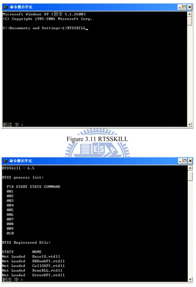
Figure 3.11 RTSSKILL...45
Figure 3.12 RTX process list ...45
Figure 4.1 Improved flip chip machine integration architecture...46
Figure 4.3 Solenoid valve arrangement ...48
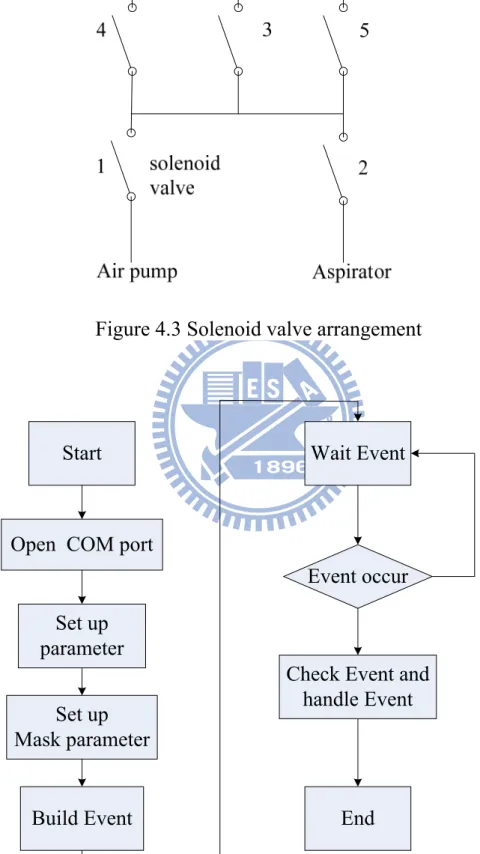
Figure 4.4 RS232 program process ...48
Figure 4.5 Force control resolution ...49
Figure 4.6 Three sets of IDM and carrying platform ...49
Figure 4.7 The plane alignment architecture...50
Figure 4.8 Chip and the aligned mark ...50
Figure 4.9 Substrate ...51
Figure 4.10 Plane alignment is finished ...51
Table Contents
Table 3.1 real-time system ...52Chapter 1 Introduction
1.1 Motive
In typical semiconductor fabrication systems chips are built up in large numbers on a single large wafer of semiconductor material, typically silicon. The individual chips are patterned with small pads of metal near their edges that serve as the connections to an eventual mechanical carrier. The chips are then cut out of the wafer and attached to their carriers, typically via wire bonding such as Thermosonic Bonding. These wires eventually lead to pins on the outside of the carriers, which are attached to the rest of the circuitry making up the electronic system. Flip Chip technology is a kind of chip packaging technology. Flip chip technology assembly is the direct electrical connection of face-down (hence, "flipped") electronic components onto substrates, circuit boards, or carriers, by means of conductive bumps on the chip bond pads. And then the flip chip technology is named because that links directly the bump that is flipped on the chip connection with the substrate board.
Flip Chip technology offers the highest speed electrical performance of any assembly method. Flip Chip technology eliminates bond wires to reduce the delaying inductance and capacitance of the connection by a factor of 10, and shortens the path by a factor of 25 to 100. The result is high speed off-chip interconnection.
Flip Chip technology gives the greatest input/output connection flexibility. Wire bond connections are limited to the perimeter of the die, driving die sizes up as the number of connections increases. Flip Chip technology connections can use the whole area of the die,
accommodating many more connections on a smaller die.
Flip Chip technology eliminates packages and the bond wires reduces the required board area by up to 95%, and requires far less height. Weight can be less than 5% of packaged device weight. Flip Chip technology is the simplest minimal package, smaller than Chip Scale Packages (CSP’s) because it is chip size.
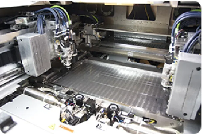
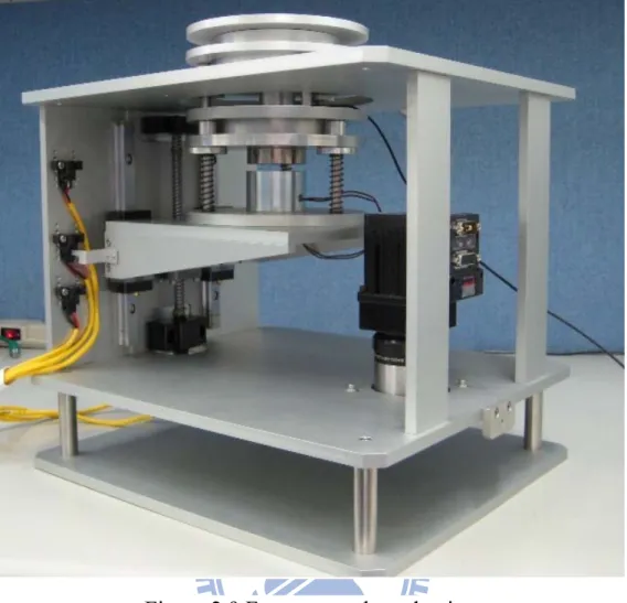
The traditional flip chip machine (shown as Figuare.1.1) uses the hydraulic cylinder to control the force and lead screw to locate. But using the hydraulic cylinder will have the stick-slip effect that make the force too large to let the chip crack. Using the lead screw to position will have the backlash effect that exist the nonlinear element. Now the positioning resolution is in 2um, and power control resolution is in the 100g. This study wants to improve this resolution. Set the positioning resolution is in 0.2μm, and force control resolution is in 20g.
1.2 Method
This thesis mainly improves a traditional Flip Chip Machine using the circular positioning mechanism of non-transmission chain to drive. It can eliminate the nonlinear problems of the backlash effect, and can solve the accuracy of the flip force control by the two-stage force feedback control methods.
Finally, it will integrate the flip chip machine on the WINPC32 by taking the Programmable Logic Controller(PLC) [1] as the control center, and taking the Function Block Diagram(FBD) as the control language, combined with Visual C+ + language. Because the requirement of the
real time, we use the software of the RTX system to achieve.
1.3 Thesis Structure
At first, the motive and method is in chapter 1. In chapter 2, we talk about the old and the improved Flip Chip Machine. The chapter 3 introduces the tool of the software and the hardware. And then, the design of the improved Flip-Chip Mechanism is mentioned at chapter 4. Finally, the conclusion is in chapter 5.
Chapter 2 Flip-Chip Mechanism
2.1
Flip-Chip Mechanism
Flip Chip technology (shown as Figuare.2.1) is a connection between the chip and substrate of the packaging technology. In the process of packaging, the chip will be flip over to connect the pads above the chip and the substrate. As the cost and process factors, the flip chip bonding product usually are divided into two forms, one is the low I / O number of FCOB (Flip Chip on Board, flip chip assembly) and the other is the high I / O number of FCIP (Flip Chip in Package, flip chip packaging).
Flip Chip Technology makes use of the substrates including ceramics, silicon, polymer laminates, and glass. Its applications include high-level computers, PCMCIA cards, military equipment, personal communications products, and liquid crystal displays. Using Flip Chip technology has two benefits:
1.Can reduce the chip and substrate of electronic signal transmission distance, high-speed devices for packaging.
2. Can be reduced the chip size package, making the chip package about the size is same after the bonding.
Traditional flip chip machine is using the pneumatic cylinder to drive the vacuum suction plant to move upward by the feedback control. But the feedback control is limited by the stick slip effect of the pneumatic cylinder. So it is difficult to obtain exact force accuracy. And the traditional flip chip machine positioning mechanism on the x- axle, y-
axle, and rotational are complex, and the transmission chain exists the backlash in the position feedback control, it is difficult to precisely control because the nonlinear elements.
Stick-slip effect (shown as Figuare.2.2) is caused by the surfaces alternating between sticking to each other and sliding over each other, with a corresponding change in the force of friction. Typically, the static friction coefficient between two surfaces is larger than the kinetic friction coefficient. If an applied force is large enough to overcome the static friction, then the reduction of the friction to the kinetic friction can cause a sudden jump in the velocity of the movement.
2.2 The Improve
Flip-Chip Mechanism
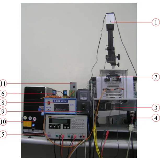
The improve flip-chip mechanism (shown as Figuare.2.3) include three parts:Micro-stepping mechanism、Self-Aligned mechanism and Force Positioning mechanism. These three mechanisms are synthesized by many of the sensors and the actuators. The following is the structure of the whole flip chip machine:
(1) IP camera:Having the CS Mount lens can be replaced, remote monitoring, as long as you can browse the web, or send images via
Email or FTP. The image Specification as follows: Compression format: MPEG4/MJEPC
Video format: AVI Number of shots: 30fps
Image resolution: 320 x 240
(2) IDM:Precise positioning for flip chip mechanism
(3) Electromagnet: Control the size of the load bearing between the suction of the carrying platform through the electromagnet and the magnet.
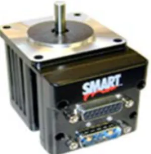
(4) SmartMotor:This servo SmartMotor represented for the Sensitive Stone company, as shown in Figure 2.4. The communication between servomoter and computer take RS232 9600 bps, no parity, 8 bytes, 1 stopbit
(5) Power Supply:It is an programmable Power Supply PR9000. It offers the RS232 interface to use the computer to control it. As long as input the instructions specified via the rs232, we can control by the computer. The communication between Power Supply and computer take RS232 9600 bps, no parity, 8 bytes, 1 stopbit.
(6) Solenoid valve:Be the switch of the air pump and the suction machines
(7) Relay:R1-00, as shown in Figure 2.5, Coil Voltage 5V, can control the solenoid valve’s state.
(8) Force sensor:Measure the strength of the value of platform. (9) Heater:Use to heat the chip.
(10) Computer: The control center
(11) Leader-5017:It is an ethernet-based 8-CH isolated analog input module. The specification as follow:
Channels: 8, differential Resolution: 16-bit
Programmable Input Range:
Supports Different Input Range for Different Channels Voltage: ±10V, ±5V, ±1V, ±500mV, ±150mV
Current: ±20mA (Jumper Setting Enabled 125Ω Resistor) Sampling Rate: 10 samples/sec (total)
Power Input: 24VDC nominal, 18 to 32 VDC Power Consumption: 125mA @ 24VDC max.
(12) PCI8516: As shown in Figure 2.6 has the analog output and the digital I/O.
Analog Outputs
Channels: 6
Resolution: 16-bit
Output voltage: +/-10V
System and General Digital I/O
System I/O Channels:19 D/I and 7 D/O General I/O Channels: 16 D/I and 10 D/O Output voltage: 10-40VDC
2.2.1 Micro-Stepping Mechanism
The mechanism is a modified impact drive mechanism (IDM) [2] which belongs to the stick slip device of pulse type. The general operating principle of IDM receives the asymmetric voltage triangle waveform. The PZT actuator is connected between slider and counter-mass of IDM and then the IDM causes a series of stick-slip motion powered by PZT actuator on the guide way. Three PZT actuators on a circular plate will compose a planar, as shown in Figure 2.7. We
change the duty-ratio and frequency of the triangle wave in the three IDM to let the circular plate move or rotate.
2.2.2 Self-Aligned Mechanism
The Self-Aligned Mechanism [3], as shown in Figure 2.8, constitute by the gas bearings, springs and pneumatic cylinders. It minimizes the friction by air pressure. It is easy to adjust the upper and lower substrate to match each other, so that the upper and lower substrate is coplanar. It can prevent the non-coplanar problems when the flip chip bonding. There are the solenoid valves to control the switch of the air pump and the aspirator. Let the air pump and the aspirator alternate open to make the upper and lower substrate is coplanar.
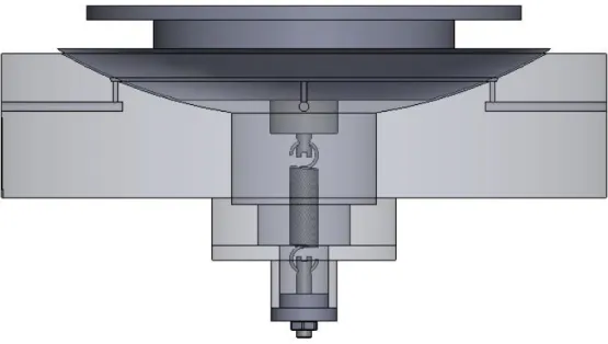
2.2.3 Force Control Mechanism
The flip-chip machine is designed the Z-axis localization and the force control organization. Using the SmartMotor actuates the lead screw to do the platform moving in the first stage. The second stage use electromagnet and spring to slowly rise the platform to the position of the pressure, then recombines load cell which display the pressure value, makes the force feed back to control magnetic force size of the electromagnet to reach the expected force resolution. The localization and the force control organization contain the lead screw, the step motor, the compression spring, the load cell, the electromagnet. In the second stage, the main linkage strength is depended on the electromagnet current to decide. The force control mechanism as shown in Figure 2.9.
Chapter 3 Software Introduction
3.1 WINPC32 Introduction
WINPC32 is a state of the universal, programmable controls and HMI platform developed by Hurco Automation Ltd [4]. The foundation layer of the WINPC32is PC-based hardware, Windows based, real time operating system. Built on this foundation is a suite of "soft", programmable, industrial controls modules which encompasses Soft-PLC, process PID, Soft-Motion, industrial networking and machine vision. The "real time kernel" is incorporated to enable Windows to achieve 100 µs level of sample time. The SoftPLC complies with IEC61131-3(e.g. standard c, JAVA) and offers all main types of PLC editing languages, like Ladder Diagram, (LD), Instruction List, (IL), Structured Text, (ST), Function Block Instruction (FB). The programming environment of all other modules, such as motion and HMI, is also compatible with major industry standards. Through a precise arrangement between the real time kernel and WIN32 layers, the WINPC32 is able to offer various real time levels to implement different applications.
3.1.1 The Open Construction
The open construction, as shown in Figure 3.1, is the user only need to follow the uniform interface modular design program, then develops the application software, various modules may be alone, may also allow to trade under the condition, but does not affects the original program
construction. With various utility parts, equipment, operation unit complete the whole open constructions, but must observe the priority-rating and the process control. Therefore personal computer and control entity essential existence exchange interface, change each other’s data in the immediate, this mechanism is called the Virtual Device, the operation pattern like Figure3.1. The open system includes the human-machine interface, Kernel and monitor manager at last, ensures security of the system operation.
3.1.2 WINPC32 Architecture
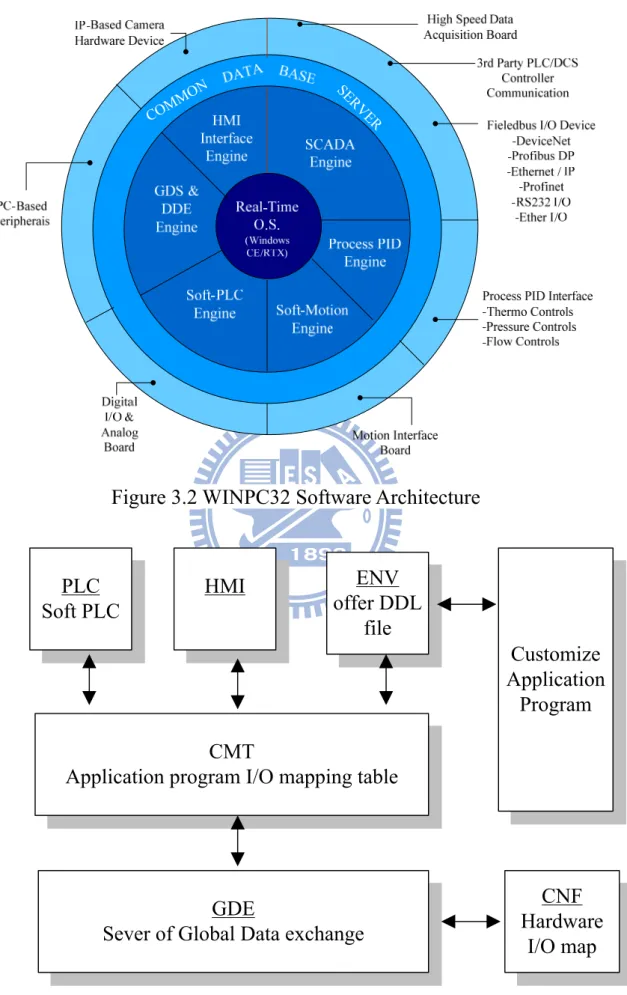
The WINPC32 is a configurable and scalable platform for Programmable controls plus HMI [5]. The software architecture is as shown in Figure 3.2. And the WINPC32 software part interrelationship is as shown in Figure 3.3. All the selection soft functions and hardware modules in an application will be configured and programmed in a single, integrated development workbench. The main components in the development workbench are:
1 Tag Builder:
The purpose of Tag Build is the tool to build the Tag data base in which each tag corresponds to a variable or parameter user needs in his application software modules. When building a tag, user is asked to type in its tag name, the type of variable, mapped address and optional comments.
2. Hardware I/O Configuration:
The purpose of this tool maps the defined software I/Os to real hardware selected for a system. The hardware I/O supported in
WINPC32 includes the local ones assigned from various PC-Bused Add-On cards (digital I/O board, analog I/O board, process PID interface board, motion interface board and data acquisition board) and remote ones supported from various field bus slave I/O and device nodes or controls like PLC or temperature controller. The way the remote data is able to be included in the system is implemented by the SCADA Engine through communication drivers or OPC Servers via communication master cards or direct serial link through COM or Ethernet ports once the I/O is configured.
3. Soft-PLC Editor:
This component offers four major PLC programming languages: (A) Ladder Diagram, LD.
(B) Instruction List, IL. (C) Structured Text, ST
(D) Function Block Instruction (FB) for user to program his logic controls. In addition, WINPC32 also offers standard C language for logic programming. The C programming can be used for partial (just a customized function) or the entire logic controls.
4. PID Controls Configuration:
This component configures the input /output of each PID loop, corresponding to I/O or other variable. Also it setup the controls parameters like PID gains for ON-OFF, PID.
5. Graphic Programming Editor (GPeX):
setups security and remote monitoring. 6. Run-Time Engine:
This component includes GDS(Global Data exchange Server) and DDE(Dynamic Data Exchange) Server run time engines. The GDS is responsible for executing the hardware and software modules the user has selected and configured as a hybrid system at a predefined priority and timing. The DDE Server offers a data exchange link to a 3rd Party Windows software which supports DDE data exchange for real time exchanging data between the software and a WINPC32 system.
7. System Configuration Utilities: This component include:
(A) Download CE Utility: It is an integrated tool for WINPC32 to produce or maintain its WinCE platform image. It encompasses Data Transfer, Remote Connection, Database Convert, Configuration and Update Windows CE O.S.
(B) User Management: a tool used for managing user passwords for all levels in WINPC32.
(C) RTX Setting: a tool to configure a WINPC32 or a custom module which runs as a RTSS module.
(D) Start-Up Setting: configure the initial, start up environment for a WINPC32 Run Mode application and its corresponding Windows OS, including the turn on/off pages displayed by Windows.
8. System Diagnostic Tools:
WINPC32provides a series of tools for debugging and diagnostics. They are:
(A) Data Center: It is used for cross-reference and searching the tag name you apply in all the segments in the Soft-PLC module.
(B) Simulate Browser: used for monitoring the common data base and simulating by manipulating the data.
(C) System Information: provide system level information.
(D) Logic Scope: graphic tools to monitor the time sequence of a Bit type tag.
(E) File Comparison Tool: to quickly analyze and mark the difference between two files.
(F) Battery Backup RAM Test Utility: Monitor the data in the Backup RAM.
(G) Error Log/Viewer: monitor all error message display in a WINPC32® application.
(H) MDB Editor: a tool to build/edit a Microsoft MS ACCESS database.
3.2 Programmable Logic Controller(PLC)
A programmable logic controller (PLC) is a digital computer used for automation of electromechanical processes, such as control of machinery on factory assembly lines, amusement rides, or lighting fixtures. PLCs are used in many industries and machines. Unlike general-purpose computers, the PLC is designed for multiple inputs and output arrangements, extended temperature ranges, immunity to electrical noise, and resistance to vibration and impact. A PLC is an example of a real time system since output results must be produced in response to
input conditions within a bounded time, otherwise unintended
3.2.1 PC-BASE
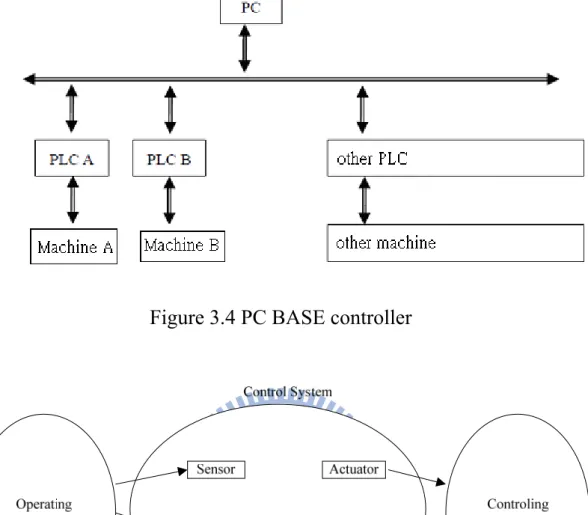
The PC-BASE development type construction is the mainstream tendency which the current controller develops. PC-BASE was still uses the personal computing is the basis, the development attachment control interface card and the related software conformity becomes the system. Figure3.4 is common PC BASE controller schematic drawing. The hardware take industrial computer as the main body, the coordination is related I\O board and the motion control panel combination. The software is in operating systems under DOS\ Window95\NT\CE develops completes, including man-machine interface, programmed control and motion control software and so on. The open style construction is hoped that the hardware can need to expand along with the user, like I \ O board, axis card, server and so on. The software can supplement the other program like to join the network function, CAD/CAM and so on
3.2.2 Development board
To develop a system, it’s inevitable to choose the target board. It must be careful to choose the target board, because it catches up in the development environment and the technical support.
3.2.3 CISC V.S. RISC
In the development of the embedded system microprocessor, it can be divided into two kinds of architecture according to the characteristic of
the instruction: CISC (Complex Instruction Set Computer) and RISC (Reduced Instruction Set Computer).
RISC architecture makes use of a small set of simplified instructions in attempt to improve performance. These instructions consist mostly of register-to-register operations. Only load and store instructions access memory. Since almost all instructions make use of register addressing, there are only a few addressing modes in a reduced instruction set
computer and there are a large number of general-purpose registers. Another way in which reduced instruction set computers sought to
improve performance was to have most instructions complete execution in one machine cycle. Pipelining was a key technique in achieving this. Pipelining allows the next instruction to enter the execution cycle while the previous instruction is still processing.
The advantages of a reduced instruction set computer: Faster.
Simpler hardware.
Shorter design cycle due to the simpler hardware.
Lower cost since more parts can be placed on a single chip. The disadvantages of a reduced instruction set computer include: Debugging can be difficult due to the instruction scheduling. Require very fast memory systems to feed them instructions. Programmer must pay close attention to instruction scheduling
so that the processor does not spend a large amount of time waiting for an instruction to execute.
instructions that correspond with each machine-language instruction. When a machine language instruction arrives at the processor, it executes the corresponding series of microcode instructions. Microcode acts as a transition layer between the instructions and the electronics of the computer. This also improved performance, since instructions could be retrieved up to ten times faster from ROM than from main memory. Other advantages of using microcode included fewer transistors, easier implementation of new chips, and a micro programmed design can be easily modified to handle new instructions sets. Another characteristic of complex instructions set is their variable-length instruction format.
Advantages of CISC include:
Less expensive due to the use of microcode.
Upwardly compatible because a new computer would contain a superset of the instructions of the earlier computers.
Fewer instructions could be used to implement a given task, allowing for more efficient use of memory.
Simplified compiler, because the micro program instruction sets could be written to match the constructs of high-level languages. More instructions can fit into the cache, since the instructions
are not a fixed size. Disadvantages of CISC:
Instruction sets and chip hardware became more complex with each generation of computers, since earlier generations of a processor family were contained as a subset in every new version.
due to their variable-length.
Many instructions are not used frequently; approximately 20% of the available instructions are used in a typical program
3.2.4 Microprocessors
From the above discussion, we can divide the microprocessors into two kinds: RISC and CISC. The following are the common microprocessors in the market.
(1) RISC architecture ARM
Each product family consists of high-performance, energy efficient designs built to handle the performance demands of today’s increasingly complex electronics applications. ARM offers the industry’s broadest range of 16/32-bit embedded RISC cores that are grouped into a range of families: the ARM7, the ARM9, the ARM10, and ARM11 of microprocessor cores.
OMAP
Produced by TI (Texas Instrument), from smart phones to high-end, multimedia-rich 3G wireless handsets and PDAs, the scalable family of OMAP processors delivers the best combination of high-performance and ultra-low power consumption.
XScale
The Intel XScale microarchitecture is based on a new core which is compliant with ARM-5TE. The microarchitecture surrounds the core with instruction and data memory management units instruction, data, and mini-data caches; write, fill, pend, and branch target buffers; power management, performance monitoring, debug, and JTAG units; coprocessor interface; 32K caches, MMUs.
MIPS
Computer Systems Inc. MIPS designs have found broad application in embedded systems, Windows CE devices, and Cisco routers. The Nintendo 64 console, Sony PlayStation console, Sony PlayStation 2 console, and Sony PSP handheld system use MIPS processors. By the late 1990s it was estimated that one in three of all RISC chips produced were MIPS-based designs
(2) CISC architecture
Mainly the x86 instruction, such as AMD-K6E, and Advantech’s x86 products.
3.2.5 Automated Part
(1) Sensor
Many automation needs to have sensor to measure system's output. The sensors may also make the suitable application, enables the controller to detect and to respond in the working conditions the variation situation. For example: The sensors may use for the setting value which the sensing three kinds need to control: Rate of fluid flow, system pressure and storage tank water level, and gauges this three kind of variables the actual value. Some sensory element like switch, uses for to examine the outputs whether to achieve the standard.
The sensory element available examines following variable: (1) the piece appearance or close degree.
(2) thing ‘s speed, acceleration.
(3) function on thing strength or pressure. (4) thing size, shape or quality.
The sensor’s output state which selects must rest on supplies decides, some sensors output the DC voltage, but some sensors output current.
Because the sensor’s output does not suits each controller's receive, therefore the sensor’s output signal must undergo the transformation, can accept the controller to induce
(2) Actuator
The actuators may change the automatic routine’s output. The actuator is controlled by the controller. Group of actuators possibly are composed by many actuators, each actuator provides the output to use to actuate other actuating units. The controller outputs the DC current signal or voltage signal to control actuator.
Some actuators just only open or the close, for example: The heater ventilator’s fans control the temperature by the temperature control system controlling switch. Other actuators become the proportion response based on receiving automatic control regulator's signal to do move. For example: variable speed motor is this reason type actuator, the flowing tubing oil pressure cylinder can control with all extends in the zero point condition or the displacement in position which the condition opens.
The actuators can change the following variable: (1) thing’s appearance or close degree.
(2) thing’s movement speed, acceleration function on thing strength. (3) thing’s temperature.
(4) thing’s fine cut lengths.
The actuator’s input state which selects must rest on its needs decides, some actuating units responded that is by the DC voltage or the
electric current, but some actuating units must AC the power source be able to operate. Some actuators have two input merits: A group connects the power supply, but another group, then connects the low power supply signal, so as to show the actuating unit to use how many power supply. Is similar to the sensors , actuator's signal demand and controller's output signal possibly has not the accommodating place, therefore, the signal alignment circuit is must.
3.3 Real-Time System
It is usually defined as those systems in which the correctness of the system depends not only on the logical result of computation, but also on the time at which the results are produced.
A real-time system usually has a time-critical mission to achieve, and a typical real-time system consists of a controlling system, a controlled system, and the environment as shown in Figure3.5. Firstly, the sensors collect data from operating environment, then the controlling system uses the data to compute, and uses the computed results to adjust the actuators properly. Because a mismatch between the state of the environment as perceived by the controlling system and the actual state of the environment can lead to disastrous results, periodic monitoring of the environment as well as timely processing of the sensed information is necessary. Thus, time is the most precious resource to be managed in real-time systems..
3.3.1 Real-Time Tasks
Computations occurring in a real-time system that have timing constraints are called real-time tasks. The computer should execute the real-time tasks so that each task will meet its timeliness requirement. In other words, a real-time task should be finished before a certain time, called the deadline [6].
In the discussion of real-time system, the deadline is usually used as the dimension to define real-time system. Real-time systems are broadly classified into three categories based on the nature of their task deadlines: (1) Hard real-time system, in which the consequences of not executing a
task before its deadline may be catastrophic
(2) Firm real-time systems, in which the result produced by a task causes to be useful as soon as the deadline expires, but the consequences of not meeting the deadline are not very severe.
(3) Soft real-time systems, where the utility of results produced by as task decreases over time after the deadline expires.
Figure3.6 depicts the relationship between value and time for different types of deadline.
3.3.2 Solve the Real-time
To solve the real issues can be categorized in two directions, both directions is to proceed with real-time system. 1. Hardware, 2. Software
as shown Figure 3.7, to make their computing core. Due to the hardware computing speed is very fast just like the double CPU systems. That can greatly reduce the CPU burden on the computer. The computer's CPU can concentrate on man-machine interface display, enabled perfecting, and the DSP CPU can deal with the motion control part of the system to address the real time issues.
◎Software real-time
Reached from the real time needs of the software required to start from the operating system, now more commonly used in industry quite a lot of real-time system, shown in Table 3.1, there VxWork, PowerTV OS, Java OS, Lino, Microware's David OS9, WinCE with plug-in Windows NT, Ardence (VenturCom) RTX ,and so on. This paper uses RTX to achieve real time.
RTX that develop by the U.S. Ardence (VenturCom) company establish Microsoft Windows operating systems in real-time subsystem. The Microsoft Windows operating system kernel provide a real-time multitasking application program development environment. RTX on the Microsoft Windows operating system adds a powerful real-time architecture subsystem (RTSS), like the other subsystems. RTSS provides an execution environment and relative API, does not use the Microsoft Windows Scheduler, using their own Scheduler. Let the scheduling of all threads are better than the original operating system scheduling priority to ensure that the real time of RTSS.
3.3.3 Windows NT Operating System
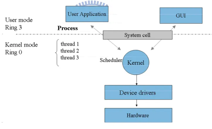
Windows NT operating system is a multitasking system [7], as shown Figuer3.8. It’s multitasking managed by the system Kernel. The multitasking structure that is good or not is depend on the real-time performance. Operating system allow the multiple applications to run concurrently, there must use the scheduler to pre-define task for scheduling. Windows NT applications cell process. But the smallest execution unit of the scheduler is not process, is the thread. Scheduling the multitasking system starts from the Micro-kernel module of the Kernel Mode to perform. The multitasking scheduling rules is to set each scheduling unit (ie, thread) the priority value and the time slice. Thread’s priority value is higher with higher implementation priority. If the implementation priority is same, judge by the time slice.
The CPU take turns to those with the highest weights of thread service. In addition, Windows NT uses the dynamic priority to balance the execution time of the user input of process currently (and foreground process, and only one) and not to accept the user input of the process (background process, can be the majority). Basically, Windows NT divided the priority into 32 levels value of 0 to 31, where 0 ~ 15 known as the dynamic range, while 16 to 31 is called the real-time range. Interrupt latency is the important indicator to evaluate the system real time performance. Interrupt in terms of the real-time system is a very important function, it represents the system capacity to handle external events. And the interrupt latency is the time when the system interrupt signals received from the hardware to begin implementation of an
interrupt service routine (ISR), but does not include the implementation of the ISR end time.
Windows NT manage the ISR by the preemptive multitasking framework. When the interrupt with higher priority occur, the lower priority interrupt will hand over the right to use the CPU until the implementation of ISR of the higher priority interruption end.
Windows NT has the feature of multitasking, providing users to perform more tasks simultaneously (such as data acquisition, real-time control, procedures, etc.). Its own the management system of the disk files, provides users with different levels of competence to access files. And the hardware abstraction layer architecture provide various types of the access interface on hardware drivers to the hardware and software.
3.3.4 RTX Real Time System
RTX developed by the VerturCom company is software as the real-time control subsystem under the Windows NT environment [8]. The real-time subsystem (RTSS) provides number of core functions and resource management programs. It can share the system under resources (including the Win32API, Memory, Hardware I / O, etc.), and support real-time control hardware features in the Windows NT operating systems. RTX provides the own fixed thread priority scheduler belongs to the software, and all the thread priority is corresponds to the Win32 thread priority to ensure that the thread can implementation under the core mode in the system like the Windows NT device driver.
architecture, making it real-time subsystem can not use Windows NT kernal, the programmer can direct control over the hardware by the API to develop the real-time applications, its respond can reach 50us, higher than the time of the Windows NT claimed 100 times more.
RTX in the hardware I / O provide a timer to allow users to deal with the planning process in a fixed period. The user can also use the RTX interrupt handler to accept an external device or the external hardware interrupt demand, combined with the timer and interrupt handlers to achieve real-time control purposes. In addition, RTX for threads also offers a number of functions, including synchronization control and four functions of inter-process communication (IPC) to be synchronized and the communication mechanism. RTX architecture is shown in Figure3.9.
3.3.5 Synchronization and Communication
Mechanism
Four functions are synchronization control- mutex, semaphore, event and inter-process communication (IPC) of shared memory.
● Mutex
If the system process many process, system process only one job once. Do the next job until the previous job is completed. For example, a number of computer want to print, the printer just only accept the control of one computer.
● Semaphore
System allows to deals with more processes once, but it has the restriction. When the workload reaches its restriction, the system will
temporarily stop the work. For example the elevator can only burden three passengers, when a fourth person want to enter the elevator, the elevator will send out a warning sound. Does not allow the next passengers to log in place, unless there is an passenger to leave.
● Event
When the setting condition establishes, the interrupt event of actions is triggered off. For example, the temperature device is set, when the temperature reaches 80 degrees the equipment is a warning, to reach 95 degrees is shut off the device.
● Share Memory
The internal data communicate each other by the share memory, as shown Figure3.10. Such as Win32 users in the man- machine interface that want to issue a command to pass a signal to the RTX system must use the way of the share memory. This command (data) saves the memory, then the RTX real-time operating system get out the by the command (data) by the memory. Share Memory is a bridge of the data transmission between Win32 and RTX.
3.3.6 RTX Timer
RTX is the most valuable parts of Timer in its very fast and accurate, this is stable of RTX Timer to do real time action.
This paper uses the clock_2, and change the timer value to 100 microseconds. The clock type is as shown in Table3.2.
3.3.7 Problems Encountered at RTX system
When I write the program at RTX has encountered some problems, if there are experiencing the same problem can be used as reference.
● Error message: RTX NT Starvation Timeout (5000us)-AllRTSS
processes stopped.Debug and/ or use "RTSSkill" command to unload all process images
(Proc:81CA3A8, Thread:81BE4008 )
Solve:Check whether you were clogging up the memory or not.
● Error message:file failed to load and start as an RTSS proess
Solve:The problem here is a bad RTX installation. Since the Add/Remove Programs Wizard cannot run, RTX will need to be removed manually. First, stop the RTX subsystem through the RTX Properties utility (located in the Control Panel). The A3200/RTX directory will then need to be deleted. Also, all references to RTX will need to be removed from the PC's registry (including HKLM\SOFTWARE\Ardence, HKLM\SOFTWARE\Venturcom, and HKLM\SOFTWARE\VCI). After this is done the A3200 can be re-installed. Ensure that RTX unpacks and installs after the last "Next" button is pressed
● Error message:unhandle exception in sc.exe OX C0000005: Access
Violation.
Error message:CXX0030: Error: expression cannot be evaluated. Solve:Check how much memory you open. Do you have no access
out of range?
● Sometimes your rtss program will shut down, even the computer will
crash.
Solve:You can enter the Dos mode, and enter the ‘RTSSKILL’, as shown Figure3.11, to check whether the same rtss process was opened twice. The same process does not allow to open too many times. If you open too many same process, you should use
‘RTSSKILL’ to kill the process. .
Chapter 4 Flip Chip Machine Design
We use RTX system and WINPC32 to integrate the entire flip chip machine, and the entire structure as shown. We take the computer as a control center, and then take the LD5017 as a sensor to capture with external information and take the PCI 8516 as actuator to control the relay that is the switch of the solenoid valve and output the triangle wave to the IDE. The image in the IP camera that is aligned by the micro-stepping mechanism can be transmitted by the TCP/IP to the computer. And the computer can control the SmartMotor and the power supply via rs232 to achieve the force control. In the computer, we use WINPC32 to do the logic decision. The improved flip chip machine integration architecture is as shown Figure4.1.
And its operation process is as follows
1. The SmartMotor moves the force control mechanism to the Bonding position, and the relay control the five solenoid valves let the carrying platform float or suck five times in order to achieve that the carrying platform and the top plane of plane is coplanar
2. The SmartMotor moves the force control mechanism to the initial position, and the users place the chip.
3. Chip placement completed, the SmartMotor moves the force control mechanism to the Bonding position and open the heater.
4. To control the three IDE makes the chip aligned in the plane.
5. Plane Alignment is completed, and the first stage of the force control use the SmartMotor, power supply control the electromagnet current to
6. Heated a few seconds, and cooling.
7. Cooling is completed, and the SmartMotor moves the force control mechanism to the initial position.
4.1 Coplanarity part
When the SmartMotor moves the force control mechanism to the Bonding position, and the relay control the five solenoid valves let the carrying platform float or fixed. First, the relay let the solenoid valve of aeration open and the relay let the solenoid valve of aspirator close, and the carrying platform floats. Next, the relay let the solenoid valve of aspirator open and the solenoid valve of aeration close, and the carrying platform is fixed. Repeat five times, We will find out the value by the force sensor measure when the solenoid valve of aeration open and the relay let the solenoid valve of aspirator close will gradually become same, and the carrying platform and the top plane of plane is coplanar. The solenoid valve arrangement is as shown Figure4.3.
4.2 Force Control part
The flip-chip mechanism is designed the Z-axis localization and the force control organization. Using the SmartMotor actuates the lead screw to do the platform moving in the first stage. The second stage use electromagnet and spring to slowly rise the platform to the position of the pressure, then recombines load cell which display the pressure value, makes the force feed back to control magnetic force size of the electromagnet to reach the expected force resolution. The localization
and the force control organization contain the lead screw, the step motor, the compression spring, the load cell, the electromagnet. In the second stage, the main linkage strength is depended on the electromagnet current to decide. And the RS232 program process is shown in Figure4.4.
4.2.1 First stage
Using the DC servomotor with the lead screw, the linear slide, and the belt do the Z axis vertical positioning systems, and increases the motor torsion by using the speed reducer that reduction gear ratio is 10:1, then the Z axis platform of the most high loading increase, and uses 2000 counts/rev encoder to read SmartMotor step to do feed back control. There are three limit switches to observe the platform path domain to prevent to hit machine.
When the user enters the desired force value, the motor will slowly put the flip chip mechanism up, and the chip on the carrying platform will touch the upper substrate, then the force value is increased. When the force value increased over the input values few 50, the motor will stop, completed the first stage force control.
4.2.2 Second stage
Take the DC electromagnet, the spring and the load cell does as the flip chip linkage force control system. This organization takes advantage of the characteristic of electromagnetic force with the magnetic material. Controlling the linkage force is executed because of us gives electromagnet the initial current first and has the electromagnetic force.
springs to compress. There is 200g preload. After the localization is completed, we reduce gradually the electromagnetic current by once 0.001A to reduce electromagnetic force, when the electromagnetic force is smaller than the spring’s strength, they will cause the sliding panel with the carrying platform to receive spring's upward thrust force. But the carrying platform already compresses the chip, therefore the sliding panel will receive the upward thrust force of a small upward displacement. The upward thrust force by small displacement will create force, also will be the linkage force which we will control.
When the first stage of the force control is end, we reduce gradually the electromagnetic current by once 0.001A to reduce electromagnetic force until the new force value is equal to the enter value. The resolution is shown as Figure4.5.
4.3 Plane Alignment part
Piezoelectric actuator is an efficient driver for micro-stepping mechanism, and it comes with several advantages such as its power-saving function, less noise, compact size, sensitivity, and high precision.
On the carrying platform top, we put three sets of IDM, as shown Figure4.6. Using the PCI 8516, output the anything style triangular wave in order to control the output of three sets of IDM, along with the observation by CCD, as shown Figure4.7. The translation and rotation experiment towards the 2-D ( 2-Dimension) of 3-DOF ( 3- Degree Of Freedom) micro-stepping mechanism is eventually for deliberating the
movement relationship between different driving waves done to the same mechanism. The users can operate the movement by exchange the parameters freely with Human Machine Interface and then capably gain the precise positioning.
We mark some frames on the chip to be an aligned mark, as shown Figure4.8. The frame’s size that will be aligned mark is the same with substrate, as shown Figure4.9. We can change the ratio of the three triangle waves, we can move the chip to the aligned placement. When the frame on the chip is overlapped with the substrate, the plane alignment is finished, as shown Figure4.10.
Chapter 5 Conclusion
We propose another method to improve the old flip chip machine,
and solve some problems of the old flip chip machine. According to the Force control mechanism, micro-stepping mechanism, and self-aligned mechanism, we can see some improvement.
(1) We have used the electromagnet and the smartmotor to successfully achieve the high resolution less than 10g. In this way, we can make the chip will not be under too much pressure and break down, to improve their process yields.
(2) The first one to apply the WINPC32 to the flip chip machine. WINPC32 will make the flip chip machine easy to control. And WINPC32 can make flip chip machine to be automatic machine.
(3) Successfully verify the instantaneous characteristic with the collocation of RTX and WINPC32.
Reference
[1] 梁富源,「WINPC32 軟體功能方塊指令之研製」,國立交通大學, 碩士論文,民國 92 年。 [2] 尤冠今,「覆晶自我校準機構之設計與實現」,國立交通大學,碩 士論文,民國 98 年。 [3] 蔡安鎮,「以衝量觀點分析二維三自由度微步進機構」,國立交通 大學,碩士論文,民國 98 年。[4] Hurco,WINPC32 Technical Manual, 1999.
[5] 張明琅,「遠距監控於射出成形製程之應用」,國立清華大學,碩 士論文,民國 93 年。 [6] 劉怡修,「可支援即時作業系統中多樣時間限制之適應性工作排 程架構」,國立成功大學,碩士論文,民國92 年。 [7] 林秉毅,「車铣複合五軸工具機 PC-based CNC 即時系統設計與實 現」,國立成功大學,碩士論文,民國 92 年。 [8] 李朝修,「以即時網路為基的控制系統研製-以串並聯機構為實 現例」,國立成功大學,碩士論文,民國 96 年。
Figures
Figure 1.1 Flip Chip package mechanism
M F
Figure 2.2 Stick-Slip effect
1
2
4
9
11
6
5
3
10
8
Figure 2.4 SmartMotor
Figure 2.5 Relay R1-00
Figure 2.7 Three PZT actuators on a circular plate
Figure 2.9 Force control mechanism
COMM
ON SER
VER
Figure 3.2 WINPC32 Software Architecture
PLC Soft PLC HMI ENV offer DDL file CMT
Application program I/O mapping table
GDE
Sever of Global Data exchange
Customize Application Program CNF Hardware I/O map
Figure 3.4 PC BASE controller
Figure 3.5 Controlled system environment
PC
DSP
Control Plant
Display
Computing
Figure 3.7 Digital signal processor
Win32 Process Win32 Process with RTX IPC RTX .DLL Win32 Subsystem Kernel and Device Drivers Windows HAL Hardware RTX RTSS (RtWinAPI)
RTX Real time HAL Extension
RTX .DLL Real-time process RTX Clock Timer interrupt Common Memory WINPC32 .exe .rtss IPC Figure 3.9 RTX architecture
Figure 3.11 RTSSKILL
Start Motor RS232 command Platform move up j=0 Aeration Platform float Aspirator Platform fixed j<5 Motor RS232 command Platform move down Place chip Power supply RS232 command I=3.000A Motor RS232 command Platform move up Open Heater Plane Alignment Force Control Criterion force Motor RS232 command Platform move up 0 F Current force k F Command force c F 100 -F + F ≥ Fk C 0 Power supply RS232 command I=3.000A I=I-0.001 0 C k ≥F +F F Cooling Motor RS232 command Platform move down Home
Figure 4.3 Solenoid valve arrangement
Start
Open COM port
Set up parameter Set up Mask parameter Build Event Wait Event Event occur
Check Event and handle Event
End
Figure 4.5 Force control resolution
Human-Machine Interface
PCI 8516
Power Amplifier
0~5V
Triangle Wave Triangle Wave0~100V
Displacement Image
Figure 4.7 Plane alignment architecture
Figure 4.9 Substrate
Table
Software Developer Product Name
WinRiver VxWork PowerTV PowerTV OS Sun Microsystem Java OS
Linux Lino Microware Microware's David
OS9
Microsoft WinCE Ardence
(VenturCom)
RTX
Table 3.1 real-time system
Clock Value Meaning
CLOCK_1 One millisecond timer.
CLOCK_2 Real-time HAL timer. Default is 500 microseconds (as specified in the registry). CLOCK_FASTEST The fastest available clock and time on the
system. This is usually CLOCK_2. CLOCK_SYSTEM Same as CLOCK_1.