國
立
交
通
大
學
電子工程學系 電子研究所
碩 士 論 文
臉部偵測應用在共享記憶體多核心系統中的平行
度分析與資料地域性之研究
Parallelism and Data Locality Analysis of Face
Detection on a Shared Memory Multi-Core
System
研 究 生:江志軒
指導教授:賴伯承 教授
臉部偵測應用在共享記憶體多核心系統中的平行度分
析與資料地域性之研究
Parallelism and Data Locality Analysis of Face
Detection on a Shared Memory Multi-Core System
研究生:江志軒 Student:Chih-Hsuan Chiang
指導教授:賴伯承 Advisor:Bo-Cheng Lai
國 立 交 通 大 學
電子工程學系 電子研究所
碩 士 論 文
A ThesisSubmitted to Department of Electronics Engineering and Institute of Electronics
College of Electrical and Computer Engineering National Chiao Tung University
in partial Fulfillment of the Requirements for the Degree of
Master of Science in
Electronics Engineering September 2011
Hsinchu, Taiwan, Republic of China
中華民國 一○○年 九月
II
臉部偵測應用在共享記憶體多核心系統中的平行度分
析與資料地域性之研究
研究生:江志軒 指導教授:賴伯承教授
國立交通大學
電子工程學系 電子研究所 碩士班
摘 要
人臉偵測在未來的智慧型裝置是一種重要的技術。然而,它的高運算量造成 其在嵌入式系統上難以實現。另一方面,平行處理和多核心架構已經成為未來高 性能計算系統的主流,將人臉偵測在多核心系統執行會是讓其在嵌入式系統上實 現的一個可行方案。要讓臉部偵測充分利用平行系統之前,我們必須把該應用的 平行度展開,才能使其應用充分的使用平行系統。本文第一部分分析人臉偵測在 該演算法不同層級的平行度。簡要介紹了臉部辨識不同層級的平行度、可拓展性 以及導致效能變差的因素,歸納分析找到提高系統整體性能的方法。根據分析結 果和設計經驗,提出了一種混合多層級平行方案,保留平行度的可擴展性和避開 會遇到的限制因素。 臉部偵測的平行度展開之後,多核心系統成了一個適當的平台,使得人臉偵 測的密集的計算量在資源受限的嵌入式系統不再是昂貴的應用。但是,大量的記 憶體存取成了運算瓶頸,限制了應用可擴展性,進一步可能使系統不能有效的運 用各核心的資源。提高資料在快取記憶體存取中的資料相依性成為一個重要的設 計問題。本文第二部分分析了維奧拉-瓊斯(Viola-Jones)演算法在平行系統的記憶 體行為,並提出了一個方案,以提高資料在快取記憶體存取時的資料相依性,減 少不必要的資料存取,降低處理器間資料網路負擔,也降低各處理器在記憶體資 源的競爭。III
因為讓平行系統的各處理器都有相同的工作量可以使系統最有效率的運算, 細粒度的執行緒負載(fine-grained thread loading)可以讓系統較容易在各處理器間 取得工作量的平衡。而粗粒度的執行緒負載(coarse-grained thread loading)也有很 多好處,不過在細粒度的執行緒負載跟粗粒度的執行緒負載之間取得平衡會造成 程式設計師額外的負擔。本文的第三部分會提出一個偷工作量(steal work load)在 粗粒度的執行緒負載上的技術,幫助程式設計師較容易讓各處理器都有相同的工 作量,使得系統較有效率,而且不會造成程式設計師太多的負擔。 歸納本文的各個部分,第一部分混合多層級平行方案,如果在記憶體存取方 面不受限制的情況,可以在六十四核心系統達到三十七點五倍的加速。然而,記 憶體存取一直是多處理器系統的瓶頸,因此第二部分針對資料區域性進行優化, 相對於原混合多層級平行方案在正常十六核心的平台下,可以減少58%的運算時間。 本文最後部分提出的偷工作量技術,可以讓系統幫助未優化的程式去改善工作量 不平均的情形,其結果接近優化過的程式,進而使得程式設計師不用花太多額外 的力氣去優化程式。
IV
Parallelism and Data Locality Analysis of Face
Detection on a Shared Memory Multi-Core System
Student: Chih-Hsuan Chiang Advisor: Bo-Cheng Lai
Department of Electronics Engineering
Institute of ElectronicsNational Chiao Tung University
ABSTRACT
Face detection is one of the fundamental technologies for future smart devices. However, its high computation makes applying such technique to an embedded device difficult to realize. Parallel processing and many-core architecture have become the mainstream to achieve high performance in future computing systems. The parallelism of an application needs to be exposed before being exploited by the parallel architecture. The first part of this thesis performs a comprehensive analysis on the parallelism of a face detection algorithm at different algorithmic levels. This thesis demonstrates that each parallelism level has its own potential to enhance performance, but also imposes some limitations. Based on the results and design experience, this thesis proposes a multi-staged mixed-level parallelization scheme to maintain the performance scalability and at the same time avoid the limiting factors.
The intensive computation requirements make the object detection an expensive application running on the resource-constrained embedded device. Due to the parallelism exposed in first part of this thesis, parallel processing on multi-core systems boosts the overall system performance. However, the memory bottleneck limits the performance scalability. Improving data locality of the on -chip cache has therefore become a critical design concern. The second part of this thesis analyzes the memory behavior of a parallel Viola-Jones algorithm, and proposes a scheme to enhance the data locality of on-chip cache. The scheme reduces unnecessary data accesses and the communication between processors and main memory.
V
Balancing the workload among processors of a parallel system enhances the execution efficiency. Implementing fine-grained threads makes it easier to achieve load balance between processors. However, using coarse -grained threads also poses many advantages. Therefore, how to strike a balance between the two parallelization schemes will become an additional burden of programmers. The third part of this thesis proposes a work-stealing design which lowers the programming effort and improves the system efficiency as well.
This paper dedicates its first part to discussing the multi -stage hybrid parallelism which achieves 37.5x speed-up on a 64-core system. However, memory accessing is an issue long existing in multi-core systems. Therefore, the second part of this paper focuses on the optimization of data locality which brings 62% reduction of computation time on a regular 16-core system. In the final part of this paper, we propose the work steal technique to alleviate the load imbalance of an un-optimized program. This mechanism can attain the similar performance to an optimized program and save programmers‟ effort on program optimization.
VI
致謝
本篇論文得以完成,首先要感謝指導教授賴伯承博士不厭其煩的指導
跟督促,在兩年的過程中,有掙扎、有徬徨,教授總是適時地給予建
議和方向,教導我研究的態度和方法。也感謝實驗室的同學、學長、
學弟們的鼓勵和幫助,使得研究能夠順利進行,像是冠儒學弟總是默
默地幫忙數據的記錄跟查詢資料,另外,也很感謝晉誠和承穎幫忙論
文校稿,使得論文的完成更加順利,幫助我過了充實的兩年研究生的
生活。最後,當然也要謝謝一直在背後默默支持我的家人和朋友們,
尤其是父母,二十多年來都是默默的支持我,真的很感謝他們,也 由
衷地感謝大家。
民國一百年九月
研究生江志軒謹致於交通大學
VII
Contents
臉部偵測應用在共享記憶體多核心系統中的平行度分析與資料地域性之研究 II
Parallelism and Data Locality Analysis of Face Detection on a Shared Memory Multi -Core
System IV 致謝 VI Contents VII List of Tables X List of Figures XI Chapter 1 Introduction 1
Chapter 2 Viola-Jones Algorithm 5
2.1 Haar-Like Feature 5
2.2 Integral Table 5
2.3 Strong Classifier and Weak Classifier 7 2.4 Algorithm flow in OpenCV 8 Chapter 3 Multi-Level Parallelism of Face Detection on Multi -Core System 11
3.1 Related work 11
3.2 Parallelism at Different Algorithm Level 12 3.2.1 Top level parallelism 12 3.2.2 Detection level parallelism 13 3.2.3 Divided detection level parallelism 14 3.2.4 Weak classifier level 15 3.3 Procedure of Different Parallelism Level 16
VIII
3.3.1 Top level parallelism 16 3.3.2 Detection level parallelism 17 3.3.3 Divided detection level parallelism 18 3.3.4 Weak classifier level 18
3.4 Hybrid Parallel Scheme 19
3.4.1 2-stage hybrid parallel scheme 19 3.4.2 3-stage hybrid parallel scheme 21 3.5 Summary of parallelism on face detection 23 Chapter 4 Enhancing Data Reuse Of Local Cache For A Parallel Object Detection
Algorithm 24
4.1 Related work 25
4.2 Data-locality of classifier vs. data-locality of pixel 26 4.2.1 Data-locality of classifier 27 4.2.2 Data-locality of image pixel 28 4.3 Classifier-First Strategy Algorithm 30 4.3.1 Change loop level of Viola-Jones algorithm 30 4.3.2 Use queue storage to replace screen window location storage on
Classifier-first strategy 32 4.4 Mathematical Model Analysis 34 4.5 Mix Classifier-First Strategy and Screen-Window-First Strategy 34 4.6 Summary of Higher Data-Locality Algorithm 38 Chapter 5 Balance Thread Loading by Steal Work Load on Coarse-Grained Thread
IX
5.1 Related Work 39
5.2 Idea of Steal Work Load on Coarse -Grained Thread Loading 41 5.3 The SW/HW organization of Steal Work Load on Coarse-Grained Thread Loading 42
5.4 Experiment Result 44
5.5 Summary of Steak Work Load on Coarse -Grained Thread Loading by Start
Value and End Value 47
Chapter 6 Platform and Other Discussion 48
6.1 Simulation Platform 48
6.2 Does Thread Scheduling improve the performance of Face Detection on
Multi-Core System? 49
6.3 The Contrast of Different Images Detect Faces on Multi-Core System 49
Chapter 7 Conclusion 55
X
List of Tables
Table 1: The computation of different strong classifiers when system detect image “lena” from OpenCV ... 33 Table 2: Number of weak classifier which the strong classifier includes ... 35 Table 3: The comparison of original architecture and work steal technique with
latency 1/1 ... 46 Table 4: The comparison of original architecture and work steal technique
with latency 8/8 ... 47 Table 5: The computation of different strong classifiers when system detect
image “baboon” from OpenCV library ... 52 Table 6: The computation of different strong classifiers when system detect
image “airplane” from OpenCV library ... 53 Table 7: The computation of different strong classifiers when system detect
XI
List of Figures
Figure 1: Haar-like feature ... 5
Figure 2: Integrates the image to integral table ... 6
Figure 3: Use the integral table to compute sum of rectangle ... 7
Figure 4: The training process of Ada-boost ... 8
Figure 5: The procedure of face detection implementation ... 9
Figure 6: The parallel scheme of face detection at top level parallelism ... 13
Figure 7: The breakdown of total execution time ... 13
Figure 8: The parallel scheme of face detection at detection level parallelism .. 14
Figure 9: The parallel scheme of face detection at divided detection level parallelism ... 15
Figure 10: The parallel scheme of face detection at weak classifier parallelism 15 Figure 11: The total execution time of different parallelism level with latency 1/1 ... 16
Figure 12: The behavior of top level ... 17
Figure 13: The behavior of detection level ... 18
Figure 14: The behavior of weak classifier level ... 19
Figure 15: 2-stage hybrid parallel scheme ... 20
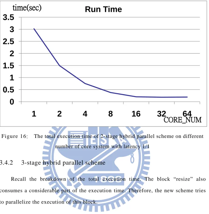
Figure 16: The total execution time of 2-stage hybrid parallel scheme on different number of core system with latency 1/1 ... 21
Figure 17: The breakdown of total execution time with latency 22/33 ... 22
Figure 18: 3-stage hybrid parallel scheme ... 22
Figure 19: The total execution time of 2-stage hybrid parallel scheme and 3-stage hybrid parallel scheme on different number of core system with latency 1/1 ... 23
Figure 20: Total execution time of face detection on different number of core system; this figure shows that bus traffic jams beco me the bottleneck when the system has many cores. ... 24
Figure 21: Pseudo code of the Viola-Jones algorithm ... 27
Figure 22: Move the scan window to a new position, the image data covered by the scan window will be checked by same cascaded classifiers. ... 28
XII
Figure 23: Location of weak classifiers of strong classifier 0 in the scan window 29 Figure 24: Location of first five weak classifiers of strong classifier 1 in the scan
window ... 29
Figure 25: The probabilit y distribution of position is read b y one weak classifier ... 30
Figure 26: Pseudo code of the modified Viola-Jones algorithm ... 31
Figure 27: The total execution time of 3-stage parallel scheme and locality optimization with latency 10/10... 32
Figure 28: The total execution time of 3-stage parallel scheme and locality optimization with use queue storage with latency 10/10 ... 34
Figure 29: Pseudo code of the Viola-Jones algorithm cascade classifier0-3 and cascade4-5 ... 35
Figure 30: Performance comparison between the 3 -Staged Hybrid Scheme and the proposed locality optimized scheme with latency 10/10 ... 37
Figure 31: Distributed task queue ... 39
Figure 32: Pseudo code of steal work load on coarse-grained thread loading ... 42
Figure 33: The block diagram of work stealing on coarse-grained thread loading by start-value and end-value. ... 43
Figure 34: The behavior of work stealing ... 44
Figure 35: The SW/HW organization of a multi-threaded shared-memory SMP simulator. The system parameters are shown on the right hand side ... 48
Figure 36: The image “people_2” on the left hand side, and the image “people_3” on the right hand side ... 50
Figure 37: The total execution time of different images with latency 10/10 ... 51
Figure 38: Image “baboon” from OpenCV library whose size is ... 52
Figure 39: Image “airplane” from OpenCV library whose size is ... 52
Figure 40: Image “tasty” size is 912 ... 53
Figure 41: Ratio of passing first three classifiers ... 54
1
Chapter 1 Introduction
Intelligence has been considered as one of the most important features for modern smart mobile devices. These devices are able to recognize the surrounding environment through sensing various types of stimuli, including vibration, orientation, temperature, sound, images, video, and etc [1]. With the awareness of the surroundings, a smart device can make decision and react intelligently to specific stimuli or events in real-time or within acceptable latencies. For example, modern tablets can sense the orientation of the device through gyroscopes and adjust the screen orientation for users [2]. The future smart application can perform even higher levels of intelligence. For example, to automatically indentify different users, or even search the customers‟ background in real-time during a business conference [3].
Among all the different types of stimuli, images and real -time video have the richest information about the environment. Images and video contain information close to the level of human eyes. A digital camera can identify human faces in the target zoom and tune the best focus for the picture. A game console can recognize the movement of players through the embedded image sensor, and let the player control the console without a physical controller [4]. However, processing this information requires an intensive computation capability. It is estimated to take about 2 seconds to recognize an object in an image of 720*576 pixels on a 2.33GHz Intel® Core™ 2 Quad processor [5]. Even with such a powerful processor, the execution time is 50 times slower than the requirement of a real-time application (processing at least 25 frames per second). This computation requirement poses an even more difficult goal for a portable embedded device, which is highly constrained in computation resources.
Parallel processing and many-core architecture have become the mainstream to achieve high performance in the future computing systems. Embedded processor
2
vendors, such as Tilera[6], ARM[7], MIPS[8], are also moving towards many-core architectures. Even the desktop processor vendors, such as Intel[ 9] and AMD[10] are proposing many-core products for embedded and mobile applications. The new parallel embedded processors present opportunities to boost the raw computing capability and achieve more energy efficient execution. However, three imperative design aspects have to be concerned before the full advantages of many-core processors can be transformed into superior system performance. First, the algorithmic parallelism of applications needs to be explored and exposed. Second, the characteristics of the highly integrated embedded system need to be analyzed. Third, the possible system bottlenecks need to be identified.
Motivated by the three design aspects, this thesis performs a comprehensive analysis on the potential parallelism of the widely used Viola-Jones face detection algorithm [11]. The analysis explores the parallelism in different algorithmic levels. By verifying the results on a multi-threaded cycle-accurate multi-core simulator, this thesis demonstrates the significant computation parallelism inherited in the face detection algorithm. However, the superior performance can only be obtained through a careful co-design and optimization crossing four critical design issues , including choosing appropriate parallelism level, balancing workload, reducing synchronization overhead, and memory and interconnect bandwidth.
The limited off-chip memory bandwidth and long access latency have imposed a limitation to the performance [12]. Efficient usage of the on-chip memory, especially the cache of processors, has therefore become a critical design issue to achieve performance scalability of embedded multi-core systems. This research analyzes the data locality of an object detection algorithm on embedded multi-core systems. Improving data locality can maximize the data reuse for on-chip caches. This can effectively avoid the off-chip memory bottleneck, and significant enhance the system performance.
3
Object detection is an indispensible function for smart embedded devices. By extracting the features in a sensed image, it is among the first step for a device to understand the surrounding environment. This thesis performed a comprehensive analysis on a Viola-Jones-based parallel object detection algorithm [11]. The object detection algorithm is parallelized by implementing the concurrent tasks with multiple threads. These threads are managed by a centralized thread queue, and are executed on an ARM-based cycle-accurate SMP (Symmetric Multi-Processing) simulator [13].
Systems with load imbalance issues are inefficient because some processors are idle while others keep executing programs. Fine-grained thread loading helps system achieve load balance among processors. It has three advantages compared with fine-grained. Firstly, coarse-grained has fewer threads, leading to less expenditure on overhead of creating threads and reading thread from thread queues. Secondly, big threads usually iterate the same loop more times than small threads do w hich indicates that the branch prediction in the coarse-grained would be more accurate than that in the fine-grained; Thirdly, because coarse-grained usually iterate same loop more times, that makes coarse-grained have higher data-locality between different iterations than fine-grained. Striking a balance between coarse-grained and fine-grained thread loading necessitates more efforts from programmers. The technique of steal work load on coarse-grained thread loading helps programmers to balance loading among processors.
the contributions of this these can be separated into three parts. The first part discusses the multi-stage hybrid parallelism which achieves 37.5X speed-up on a 64-core system. However, memory accessing is an imperative design issue long existing in multi-core systems. Therefore, the second part of this thesis focuses on the optimization of data locality which brings 62% reduction of computation time on a regular 16-core system. In the final part of this thesis, we propose a work steal technique to alleviate load imbalance of an unoptimized program. This mechanism
4
can attain the similar performance to an optimized program and save programmers ’ effort on program optimization.
This thesis is organized as follows. Chapter 2 introduces Viola-Jones-based object detection algorithm. Chapter 3 shows the multi-level parallelism analysis of face detection on a shared memory multi-core system. Chapter 4 proposes a design which enhances the data reuse of local cache for a parallel face detection algorithm. Chapter 5 shows a technique of work-stealing on a coarse-grained multi-threaded design. Chapter 6 introduces the simulation platform and discusses some related design issues. At last, Chapter 7 draws the conclusion.
5
Chapter 2 Viola-Jones Algorithm
If one were asked to name a single face detection algorithm that has the most impact in the 2000‟s, it will most likely be the seminal work by Viola and Jones. The Viola-Jones face detector contains three main ideas that make it possible to build a successful face detector that can run in real time: the integral image, classifier learning with AdaBoost, and the attention cascade structure [11].
2.1 Haar-Like Feature
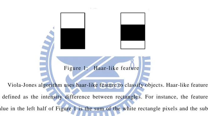
Figure 1: Haar-like feature
Viola-Jones algorithm uses haar-like feature to classify objects. Haar-like feature is defined as the intensity difference between rectangle s. For instance, the feature value in the left half of Figure 1 is the sum of the white rectangle pixels and the sub sum of the black rectangle pixels. As for the right half of Figure 1, the feature is the sum of upper white rectangle pixels and lower white rectangle pixels, and then the sub sum of the black rectangle pixels.
2.2 Integral Table
One of Viola-Jones algorithm‟s distinguishing characteristic is its use of integral image for computing the sum of value in the rectangle quickly and efficiently. Integral image, or a summed area table, was firstly introduced to the digital image processing by Crow [5] for use in mipmaps. In Viola and Jones face detection, the integral image is used for rapid computation of Haar-like features. The integral image
6
is constructed as follows.
For example, the left half of Figure 2 is the image pixel, and the right half is the integral table.
Figure 2: Integrates the image to integral table
We would find that pixel 15 in right half of Figure 2 is the sum of 1, 8 and 6 in the left half Figure 2 and pixel 20 in right half Figure 2 is the sum of 1, 7, 8, and 4.
After integrating an image, the algorithm computes Haar-like feature like Figure 3. In Figure 3, assume that the sum of block D is the result we want. We can use the value of point 4, the sum of block A and B and C and D, sub value of point 3, the sum of block A and B, sub value of point 2, the sum of block A and C, and then add value of point 1, the sum of block A. And final answer is equal to sum of block D.
7
Figure 3: Use the integral table to compute sum of rectangle
2.3 Strong Classifier and Weak Classifier
The classifier in this algorithm can be divided into two parts: strong classifiers and weak classifiers. Strong classifiers have high accuracy, so they are used in cascade architecture. When data is sent to the classifier, the first strong classifier would classify this data into true or false. If data is classified as false, it is not the target object; if data is classified as true, then it is sent to the next classifier and category. If data passes all classifiers, it includes the target object.
The result of a strong classifier depends on its own weak classifiers; in other words, weak classifiers are the elements of a strong classifier. When data is sent to a strong classifier, all of its weak classifiers compute the data to judge whether it contains a target object. If the weight of weak classifiers which return true is larger than that of the weak classifiers which return false, then the strong classifier return s true; if not, the strong classifier return false.
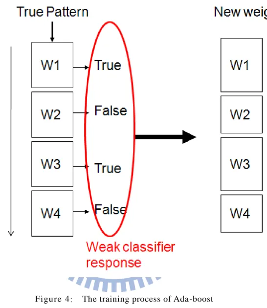
The weight of each weak classifier is trained by Ada -boost, and the main idea of Ada-boost is shown in Figure 4. In this figure, one strong classifier has four weak classifiers: W1, W2, W3 and W4. Now, we send one pattern to the classifiers, and the system knows the answer of pattern is true.
8
the system tunes the weight of them larger. W2 and W4 return false, and the response mismatches the correct answer; the system hence tunes the weight of them smaller.
Figure 4: The training process of Ada-boost
2.4 Algorithm flow in OpenCV
The face detection algorithm is divided into three blocks: “resize”, “integral” and “detect”.
The resize block changes the sizes of images. Because sizes of face are different, we need to change the image size. In real-life applications, the size of a face is not constant, so resizing is necessary. Consequently, the ratio of the scan window to the whole image needs to be modified so that the scan window can capture different sizes
9
of face.
The integral block integrates an image to a table, and the integral image helps classifier computes the feature quickly and efficiently. The procedure was introduced in Section 2.2.
Figure 5: The procedure of face detection implementation
As the detect block moves the scan window through the image, the sub-image is sent into the cascade classifier structure to detect the location of a face. The result of strong classifier depends on weak classifiers, so the strong classifier has higher
10
accuracy. Therefore, it is used in cascade architecture. If the sub-image of scan window passes all strong classifiers, it means that the scan window includes the face; if it doesn‟t pass all of the strong classifiers that mean the scan window doesn‟t include a face.
11
Chapter 3 Multi-Level Parallelism of
Face Detection on Multi-Core System
The focus of chapter 3 falls on the parallelism of the face detection application. We would be more interested in the intrinsic computation parallelism which can be exposed through parallelization. To minimize the impact of communication bottleneck, the memory/bus latency is set to 1 cycle. The rest of the chapter 3 will use this system scheme to explore the parallelism of the application.
3.1 Related work
Face detection is extensively studied used in many smart object applications [3]. The Viola and Jones algorithm is one of the most widel y used face detection schemes [11]. It provides high accuracy and fast computation. Since the algorithm is so popular, many research efforts have been spent on enhancing the performance of the Viola-Jones algorithm. Wei et al.[19] and Yang et al.[20] realized parallelism of the algorithm by using a specific HW design in a FPGA. Theocharides [21] also proposed a scalable parallel architecture for face detection on FPGA. Gao [22] presented a novel approach to use FPGA to accelerate the Haar-classifier based face detection algorithm with highly pipelined micro-architecture and utilizes abundant parallel arithmetic units in an embedded system. Most of the methods focus on using innovative HW architecture or specific HW accelerator to enhance the performance. This chapter concentrates on achieving better performance through exploiting the algorithm parallelism on multi-core systems. It is different from building a specific hardware accelerator to speed up the critical computation in the algorithm. The proposed design can be easily applied to an SMP system without any extra HW implementations.
12
Chen„s research [5] is among the first to explore the algorithmic parallelism of face detection algorithm, and is similar to the work done in this thesis. The author analyzed the potential parallelism of Viola-Jones algorithm and executed on multi-core systems with 4 to 8 processors. A 5.5X performance enhancement was demonstrated by adopting a hybrid scheme of both coarse -grain and fine-grain TLP. This chapter differs from [5] in two aspects: (1) this chapter not only explores the algorithm parallelism in different levels, but also shows the impact of different design issues; (2) the analysis is extended to a larger scale (64 cores) of multi-processor which demonstrates a significant computation parallelism in the face detection algorithm.
3.2 Parallelism at Different Algorithm Level
The parallelism of the face detection exists in different algorithmic levels. This section discusses the potential parallelism at different levels of the face detection implementation. The face detection implementation is adopted and modified from OpenCV library[14], which applies the idea of Viola-Jones face detection algorithm.
To take the advantage of multi-core platform, we need to analysis the inherent parallelism of face detection. In this algorithm, the parallelism level is divided into four levels: top level, detection level, divided detection level and weak classifier level. Detail discussions about each level can be found in following sections.
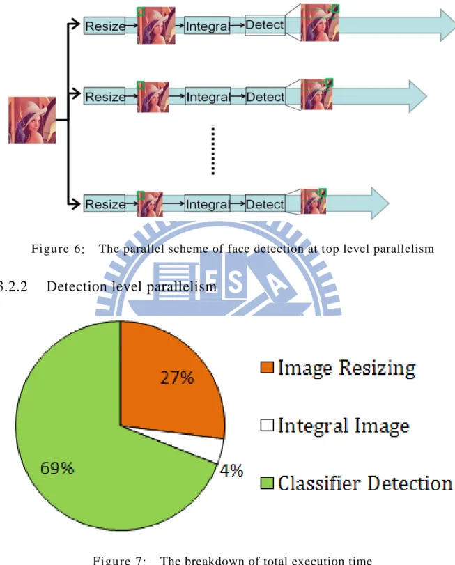
3.2.1 Top level parallelism
In top level parallelism, images with different sizes are processed by different threads. As illustrated in Figure 6, the first thread resizes the original image to the biggest image, and then integrates and detects this image. The second thread resizes the original image to a smaller image, and then integrates and detects the smaller image. And the final thread resizes the original image to the smallest image, and then
13
integrates and detects this image.
Figure 6: The parallel scheme of face detection at top level parallelism
3.2.2 Detection level parallelism
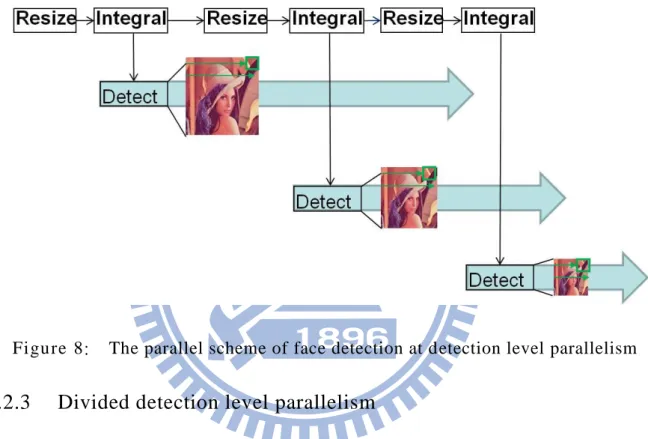
Figure 7: The breakdown of total execution time
Figure 7 is the breakdown of total execution time. And the number is simulated by cycle-accurate SMP simulator based on ARM ISA. We can find that the detection block is the significant part of total execution time, so this thesis tries to parallelize the execution of the “detect” block.
14
In detection level parallelism, the program detect s different images by different threads. As in Figure 8, the “resize” and “integral” blocks are executed sequentially. After integrates image, the biggest image is detected by the first thread. At the same time, the program keeps resizing and integrating the smaller image. After integrates image, put the image into this thread to detect and keep resiz ing. The computation loads are different due to different sizes of images.
Figure 8: The parallel scheme of face detection at detection level parallelism
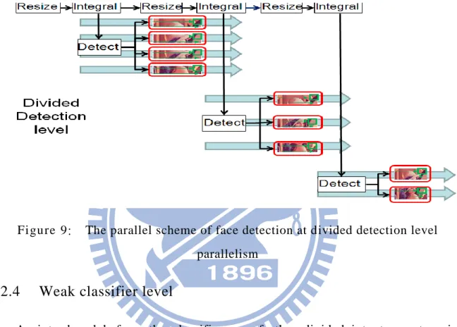
3.2.3 Divided detection level parallelism
To balance the computation loads between different threads, the program divides an image into several sub-images in the divided detection level. Big images are divided into many parts while small images are divided into fewer parts. After that, the program detects different sub-images by different threads. Program Detects a sub-image means that a thread detects all scan windows at their upper left corner in the sub-image. The program still reads pixel data from the entire image, so the final result is unchanged from that of the program which is executed sequentially, even if some scan windows cover different sub-images. The behavior of this level is shown in Figure 9. The program resizes and integrates an image sequentially. After the program
15
finishes integrating an image, the program divides the biggest image into several sub-images and then detects each sub-image by different threads. At the same time, the program keeps resizing and integrating smaller images. Again, after finishing integrating an image, the program divides the smaller image into several sub-images and then detects each sub-image by different threads and keeps resizing.
Figure 9: The parallel scheme of face detection at divided detection level parallelism
3.2.4 Weak classifier level
As introduced before, the classifiers are further divided into two categories: Strong classifier and weak classifier. A strong classifier contains several weak classifiers, and the result of strong classifier depends on its own weak classifiers. In weak classifier level, weak classifiers are executed by different threads when the program sends the image into the strong classifier.
16
3.3 Procedure of Different Parallelism Level
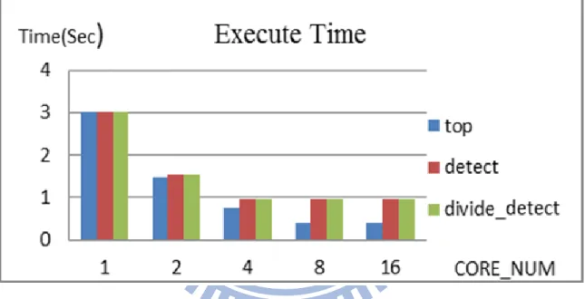
Simulation results are shown in Fig. 11 where the horizontal axis represents the number of cores, and the vertical axis represents the total execution time. In the top level parallelism, the execution time is improved as the number of cores increases. However, the increase rate slows when there are more than 8 cores. In detection level and divided detection level parallelism, the execution time is not improved when the system has more than 4 processors. In the weak classifier level, since the total execution time is too long, we don‟t show it in this figure.
Figure 11: The total execution time of different parallelism level with latency 1/1
3.3.1 Top level parallelism
In the top level, almost the entire application is parallelized, and the sequential part is minimized. However, due to different sizes of images, loadings of threads are not equal. As Figure 12 shows, some processors already finish their own program while some still need more time. That means that processors having finished their own program still need to wait for other processors, which leads to the system‟s inefficient use of its processors.
17
Figure 12: The behavior of top level
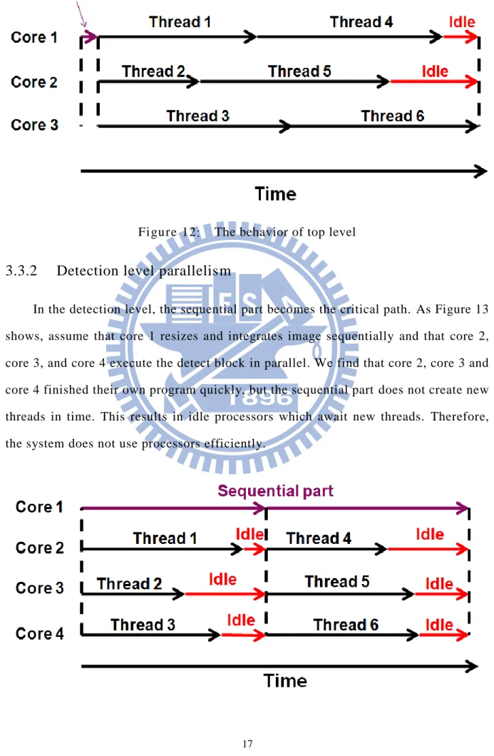
3.3.2 Detection level parallelism
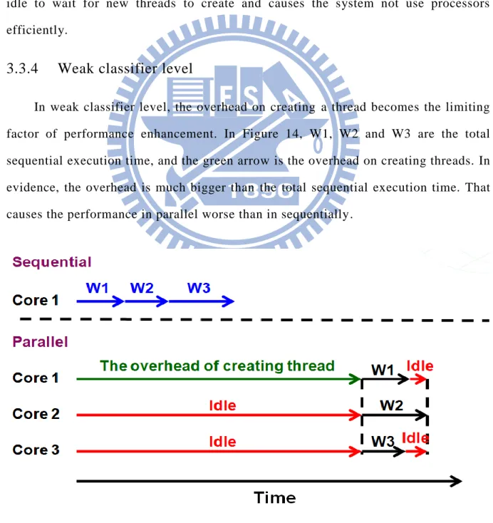
In the detection level, the sequential part becomes the critical path. As Figure 13 shows, assume that core 1 resizes and integrates image sequentially and that core 2, core 3, and core 4 execute the detect block in parallel. We find that core 2, core 3 and core 4 finished their own program quickly, but the sequential part does not create new threads in time. This results in idle processors which await new threads. Therefore, the system does not use processors efficiently.
18
Figure 13: The behavior of detection level
3.3.3 Divided detection level parallelism
In the divided detection level, fine-grained thread loading makes the system easier to achieve load balance between processors. However, similar to the situations in the detection level, the sequential part becomes the critical path.
As shown in Figure 13. The parallel parts finish their own program quickly, but the sequential part does not create new threads in time. That cause s these processors idle to wait for new threads to create and causes the system not use processors efficiently.
3.3.4 Weak classifier level
In weak classifier level, the overhead on creating a thread becomes the limiting factor of performance enhancement. In Figure 14, W1, W2 and W3 are the total sequential execution time, and the green arrow is the overhead on creating threads. In evidence, the overhead is much bigger than the total sequential execution time. That causes the performance in parallel worse than in sequentially.
19
Figure 14: The behavior of weak classifier level
3.4 Hybrid Parallel Scheme
According to the result and the above discussion, we find that in the top level, almost the entire application is parallelized, and the sequential part is minimized. But the imbalanced loading of the threads causes the system use processors inefficiently. In the divided detection level, fine-grained thread loading makes the system easier to achieve load balance between processers, but the sequential part s become the critical path.
So this thesis proposes the hybrid parallel scheme to avoid the limiting factor, and to retain the advantages of different levels. By minimizing the sequential part in programs and using fine-grained thread loading, it is easier for the system to achieve load balance between the processors.
3.4.1 2-stage hybrid parallel scheme
In 2-stage hybrid parallel scheme, the program resizes and integrates different images with different threads in the first stage. Then the scheme divides image into several sub-images. After that, the program detects each sub-image by different threads in the second stage.
As shown in Figure 15, in the first stage, the first thread resizes and integrates the biggest image, the second thread resizes and integrates the smaller image, and the final thread resizes and integrates the smallest image. In the second stage, the program divides the biggest image into four sub-images, and detects each sub-image by different threads. And then the program divides smaller image into three sub-images, and detect each sub-images by different threads.
20
Figure 15: 2-stage hybrid parallel scheme
Figure 16 shows the total execution time of the 2-stage hybrid parallel scheme. The horizontal axis represents the number of cores and the vertical axis represents the total execution time. We find in the 2-stage hybrid parallel scheme, the execution time is improved as the number of cores increases. This scheme can achieve a 15x speed-up on a 16-core system. However, the rate of improvement slows down when there are more than 16 cores. The reason is that the first stage in this scheme still has load imbalance problem when the system has more than 16 cores.
21
Figure 16: The total execution time of 2-stage hybrid parallel scheme on different number of core system with latency 1/1
3.4.2 3-stage hybrid parallel scheme
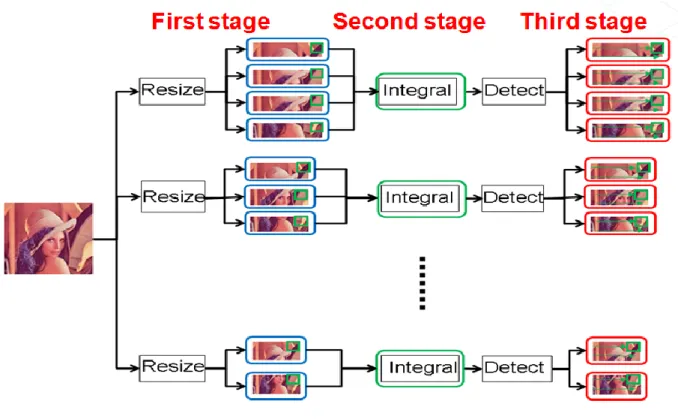
Recall the breakdown of the total execution time. The block “resize” also consumes a considerable part of the execution time. Therefore, the new scheme tries to parallelize the execution of this block.
0
0.5
1
1.5
2
2.5
3
3.5
1
2
4
8
16
32
64
Run Time
CORE_NUM
time(sec)
22
Figure 17: The breakdown of total execution time with latency 22/33 This thesis modifies the 2-stage hybrid parallel scheme and separates the block “resize” and “integral” into different stages. Then the new scheme divides image into several sub-images, and resizes each sub-image by different threads to balance the loading of threads in the first stage. Different images are then integrated by different threads in the second stage. Finally, the program detects different sub-images by different threads in the third stage.
Figure 18: 3-stage hybrid parallel scheme
Figure 19 shows the execution time of 3-stage hybrid parallel scheme. The horizontal axis represents the number of core, and the vertical axis represents the total execution time. We find that this scheme can achieve a 27.5x speed-up on the 32-core system, and achieve a 37.5x speed-up on the 64-core system.
23
Figure 19: The total execution time of 2-stage hybrid parallel scheme and 3-stage hybrid parallel scheme on different number of core system with latency 1/1
3.5 Summary of parallelism on face detection
In higher algorithm level, loadings of threads are imbalanced. That causes system to use processors inefficiently. In lower algorithm level, too many sequential parts and overheads deteriorate performance. We propose multi-staged hybrid scheme that strikes the balance between higher algorithm level and lower algorithm level. This scheme avoids the limiting factor and achieves superior performance.
24
Chapter 4 Enhancing Data Reuse Of
Local Cache For A Parallel Object
Detection Algorithm
In Chapter 3, the 3-stage hybrid parallel scheme achieved a 37.5x speed-up on 64 core system. However, Chapter 3 focuses more on the parallelism of face detection application. There are more interested in the intrinsic computation parallelism which can be exposed through parallelization. To minimize the impact of communication bottleneck, the memory/bus latency is set to 1 cycle.
Figure 20: Total execution time of face detection on different number of core system ; this figure shows that bus traffic jams become the bottleneck when the system has
many cores.
But in real system, the memory/bus latency cannot be neglected, and the communication traffic jams definitely occur. As shown in Figure 20, bus traffic jams
0 1 2 3 4 5 6 1 2 4 8 16 latency 20 RunTime latency 10 RunTime latency 5 RunTime Time(sec) Time(sec)
25
become the bottleneck when the system has many cores. Significant enhancements of performance were observable until the number of cores was up to eight. Improving data locality of the on-chip cache has therefore become a critical design concern. Improved data locality increases cache hit rate. Increased cache hit rate lowers the frequency of memory access. Lowered frequency of memory access reduces total memory access time and consequently improves the total execution time. This chapter analyzed the memory behavior of a parallel Viola-Jones algorithm, and proposed a scheme to enhance the data locality of on-chip cache.
4.1 Related work
Data locality optimization is a critical design issue for computing systems and has been studied for decades [23]. However, most of the previous research focused on single core systems. Locality issues of multi-core systems are recently emerging as essential design concerns when parallel platforms become the mainstream o f the computing architecture [24]. In a shared memory multi-core system, the design needs to be balanced between parallelism and locality in order to achieve the best overall performance.
The Viola-Jones algorithm is one of the most widely adopted object detection schemes [11]. It was first proposed to detect human faces in an image. Due to the high accuracy and fast computation, the algorithm has also been extended to detect other objects in an image or video, such as hands, eyes [25], pedestrians [26], and cars [27]. Many research efforts have focused on enhancing the performance by exploiting the algorithmic parallelism on specific HW accelerators [21]. With the increasing amount of non-recurring-cost of implementing a pure HW solution, exploiting the parallelism on a programmable multi-processor system has become cost attractive in designing future intelligent algorithms.
26
the Viola-Jones-based detection algorithm on programmable processors. This work analyzed the potential parallelism of the Ada-boost algorithm and executed on multi-core systems with 4 to 8 processors. A 5.5X performance enhancement was demonstrated by adopting a hybrid scheme of both coarse-grained and fine-grained TLP. Chiang [28] investigated the characteristics of different parallelism levels of a Viola-Jones algorithm. The authors have proposed a three -staged parallelization scheme to improve the load balance of the algorithm and achieve 37X performance improvement.
This chapter differs from the previous works in two aspects: (1) the target platform of this work focuses on embedded multi -core systems, where each processor is a simple single issue RISC core with relatively small on-chip caches; (2) this work concentrates on the data locality optimization for the parallel object detection algorithm and proposes a design to improve the memory access behavior as well as overall performance.
4.2 Data-locality of classifier vs. data-locality of pixel
As shown Figure 21, the implementation of Viola-Jones algorithm can be divided into three parts. (1) Resize. The implementation uses the fixed -size scan window with a well-trained classifier library in the Ada-boost algorithm. Since the scan window size is fixed, an image needs to be resized into different resolutions. (2) Integral. This part performs the evaluation of the Haar-like features by using the integral image method. (3) Detect. By moving the scan window th rough the image, the sub-image is sent into the cascade classifier structure to detect the location of an object.
27
Figure 21: Pseudo code of the Viola -J ones algorithm
4.2.1 Data-locality of classifier
The detect block contains a list of cascaded strong classifiers. Each strong classifier is composed of a series of weak classifiers. When moving the scan window to a new position, the image data covered in the scan window will be checked by these cascaded classifiers. If the image data passes all the classifiers, this window position will be marked positive, indicating the existence of a target object. In the process, the program load different pixels, but computed by same classifier. As shown in Figure 22.
Each weak classifier is responsible for checking one specific feature of the target object. Thus each weak classifier contains the associated information about this feature, including classifier types, location in the scan window, weighting factor, and the decision threshold. After the first usage of a weak classifier, the feature information will be stored temporarily in the local cache. This boosts system performance if a processor can find this information from its local cache when the next time it is trying to use the same weak classifier.
for all WZ // WZ: window size Resize image;
Integral image;
for all WP // WP: window position Detect {
for all SC // SC: strong classifier for all WC // WC: weak classifier
If failed, label the position as negative; jump to the next WP; If passed all the SCs, label the position as positive;
28
Figure 22: Move the scan window to a new position, the image data covered by the scan window will be checked by same cascaded classifiers.
4.2.2 Data-locality of image pixel
From another point of view, classifiers load different collections of pixels even if they employ the same scan window. A simple illustration can be found in Fig. 23 and Fig. 24. The program only loads the pixels on the corners to compute the intensity differences between rectangles. As shown in Figure 23, Figure 24, each weak classifier includes two or three rectangular Haar-like features. Viola-Jones algorithm uses the integral image to efficiently compute the target features. Thus each classifier only loads the corner integral data points of a Haar-like feature rectangle and computes the intensity difference between sub-rectangles. The possibility that the corners of these rectangles fall on the same data position of an integral image is fairly low.
29
Figure 23: Location of weak classifiers of strong classifier 0 in the scan window
Figure 24: Location of first five weak classifiers of strong classi fier 1 in the scan window
30
Figure 25 shows the probability that points in a scan window are loaded by weak classifiers. The average probability that a point is loaded is merely 2%, and the maximal probability is 6%. This discloses the fact that the probability of reusing a pixel is rather low. On the contrary, parameters of a classifier are definitely reusable.
Figure 25: The probabilit y distribution of position is read b y one weak classifier
4.3 Classifier-First Strategy Algorithm
Generally, object detection is realized by a scan window browsing through the whole image, and the sub-image contained in the window is sent to the cascade classifier. This is an intuitive combination of a cascade classifier and scan ning through the whole image. However, to deal with data locality and the issue of bus traffic jams, classifier-first strategy is a better scheme.
4.3.1 Change loop level of Viola-Jones algorithm
Based on the analysis from the previous section, we proposed a new design scheme to enhance data locality for an embedded multi -core system. Figure 26 shows the pseudo code of this new design. Different from the original algorithm flow, the
31
new design relocates Loop WP, which changes the position of the scan window, next to Loop SC (Strong Classifier).
This design improves data locality of the feature information of weak classifiers. Moving the WP loop after the SC loop can reduce the possibility for the already-cached feature information being replaced by the subsequent strong classifiers which would be loaded right after the usage of the current strong classifier in the original design.
Figure 26: Pseudo code of the modified Vi ola-J ones al gorithm
Figure 27 compares the runtime between the original algorithm and the proposed design. The cycle-accurate simulation was performed on systems with different numbers of processors (indicated by the x-axis of Figure 27). The proposed design has better performance at all the multi-core schemes. This is because the numbers of external memory accesses are reduced significantly due to the bet ter data locality at the local cache. The 16-processor scheme has the maximum performance enhancement of 53%. This is mainly because, for the original design, the potential
for all WZ // WZ: window size Resize image;
Integral image; Detect {
for all SC // SC: strong classifier
for all WP // WP: window position (New position of WP loop)
for all WC // WC: weak classifier
If failed, label the position as negative; jump to the next WP; // processor can better reuse the WC data stored in the cache // which significantly increases the data locality
If passed all the SCs, label the position as positive; }
32
performance enhancement of the original design enabled by more processors is compromised by the enormous memory access time. The memory bottleneck becomes the limiting factor of the system performance. Hence the performance stops improving when there are more than eight processors. However, the proposed design significantly reduces the number of memory accesses. The performance continues to scale when there are more processors (8, and 16 processors).
Figure 27: The total execution time of 3-stage parallel scheme and locality optimization with latency 10/10
4.3.2 Use queue storage to replace screen window location storage on
Classifier-first strategy
In order to change loop level, a strong classifier is first selected and it processes each sub-image of the moving scan window. The classifier decides whether a sub-image contains the target object and the decision is stored in memory. Later, when another classifier is selected, it only reads sub -images which were decided positive of containing a target object.
0 0.5 1 1.5 2 2.5 3 3.5 4 4.5
1 Core 2 Core 4 Core 8 Core 16 Core
3-Staged Hybrid(original) change loop
Run time(sec)
33
However, as shown in Table 1, most window position fails the feature check during the first five strong classifiers that means some extra computation in change loop algorithm when system check this position pass front classifier or not. Section 6.3 features more on the computation of different strong classifiers. We can optimize the algorithm by only check pass position. So we modify algorithm, if the position pass, record the position to a queue storage, when program execute next strong classifier, load the position from queue not check all position in image, this method help system read record table less time. The 16-processor scheme has the maximum performance enhancement of 58%.
Table 1: The computation of different strong classifiers when system detect image “lena” from OpenCV
0 0.5 1 1.5 2 2.5 3 3.5 4 4.5
1 Core 2 Core 4 Core 8 Core 16 Core
3-Staged Hybrid(original) Locality Optimized(propose)
Run time(sec)
34
Figure 28: The total execution time of 3-stage parallel scheme and locality optimization with use queue storage with latency 10/10
4.4 Mathematical Model Analysis
Section 4.1 already explained why the times of memory access of classifier -first strategy is less than that of screen-window-first strategy. In this section, we adopt a mathematical point of view to explain the results . Assume one weak classifier classes one location need to read size data (weight threshold…etc), and size pixel. And one strong classifier has N weak classifiers. In screen-window-first strategy, one strong classifier detects one location needs to load ( ); Assume this image has M locations should be detected, in classifier-first strategy, because all location use same classifier, one strong classifier detects all location needs to load ( ), in other word, one strong classifier classes one location have to load ( ), the size of the data used (read) by each weak classifier is weak classifier weight*2(true or false) + weak classifier threshold + rectangle weight*x + pixel*4*x, here x is the number of rectangle which weak classifier had, and “Load Queue” only one access, M usually is a large number, as the model shows, the number of classifier-first strategy algorithm read memory less than the number of screen-window-first strategy algorithm read memory.
4.5 Mix Classifier-First Strategy and Screen-Window-First
Strategy
35
Table 2: Number of weak classifi er which the strong cl assifier includes To sum up, classifier-first strategy achieves better data locality at the expense of extra computation and memory space for the results of previous classifier. Scan-window-first strategy, on the other hand, does not have this downside because it only comprises cascade classifiers.
Figure 29: Pseudo code of the Viola-Jones algorithm cascade classifier0-3 and cascade4-5
When old feature information of a weak classifier fill all cache, the feature for all WZ // WZ: window size
Resize image; Integral image; Detect {
for all WP // WP: window position
for SC0:SC3 // SC: strong classifier(cascade 0-3)
for all WC // WC: weak classifier
If failed, label the position as negative; jump to the next WP; for all WP // WP: window position
for SC4:SC5 // SC: strong classifier(cascade 4-5)
for all WC // WC: weak classifier
If failed, label the position as negative; jump to the next WP; for other SC // SC: strong classifier
for all WP // WP: window position (New position of WP loop)
for all WC // WC: weak classifier
If failed, label the position as negative; jump to the next WP; // processor can better reuse the WC data stored in the cache // which significantly increases the data locality
If passed all the SCs, label the position as positive; }
36
information of a weak classifier in the local cache is replaced by another weak classifier. That means if the strong classifier not fills all cache, the system load other appropriate classifier would keep the data locality possible and not replace the original classifier. That means moving the scan window and send image data to appropriate cascade classifier structure, the information of classifier would not replace before all position load this classifier and reduce record pass position time.
According to our experiment result, we find about 80 weak classifiers would fit the 16KB cache, as shown in Table 1, send position data to cascade classifier 0 to classifier 3, then record the position pass those classifier, and then send position data to cascade classifier 4 to classifier 5, then record the position pass those classifier, and then use classifier-first strategy is the best scheme when system has 16KB cache.
0 0.5 1 1.5 2 2.5 3 3.5 4 4.5 5 1 2 4 8 16 3-Staged Hybrid(original) Locality Optimized(propose) cascade SC 0-2 cascade SC 0-3 4-5 Number of processors Run tim e (se c) Dcache = 8KB Number of processors Run tim e (se c) Dcache = 8KB
37
Figure 30: Perform ance comparison bet ween the 3 -Staged Hybrid Scheme and the proposed localit y optimized schem e with latency 10/10
Because about 80 weak classifiers would fit all 16KB cache, that means 40 weak classifiers would fit 8KB cache, as shown in Figure 30, the classifier 0 to classifier 2 fit the 8KB cache, and the classifier 3 almost replace all data of classifier 0 to classifier 2 in cache, that cause the cascade 0-3 4-5 scheme performance close to 3-Stage Hybrid and worse than Locality Optimized but cascade 0 -2 still better than Locality Optimized.
When system has 32KB cache, the cache size is big, and the probability of new data replaces old data becomes fewer, so the data-locality optimal effect becomes not
0 0.5 1 1.5 2 2.5 3 3.5 4 4.5 1 2 4 8 16 3-Staged Hybrid(original) Locality Optimized(propose) cascade SC 0-2 cascade SC 0-3 4-5 Number of processors Runt im e ( se c) Dcache = 16KB Number of processors Runt im e ( se c) Dcache = 16KB Number of processors Runt im e ( se c) Dcache = 16KB Number of processors Runt im e ( se c) Dcache = 16KB 0 0.5 1 1.5 2 2.5 3 3.5 1 2 4 8 16 3-Staged Hybrid(original) Locality Optimized(propose) cascade SC 0-2 cascade SC 0-3 4-5 Number of processors Run tim e (se c) Number of processors Run tim e (se c) Number of processors Run tim e (se c) Number of processors Run tim e (se c) Dcache = 32KB
38
obvious, and then the total execution time of each scheme is closed to other.
4.6 Summary of Higher Data-Locality Algorithm
Object detection enables a smart embedded device to recognize the surrounding environment and to react properly. Nonetheless, object detection requires parallel algorithms to be executed on multi-core systems due to its high amount of computation, the memory bottleneck makes it a critical design concern to improve data locality and to take the full advantage of the on-chip cache. This thesis analyzed the memory behavior of a parallel Viola-Jones algorithm, and proposed a scheme to enhance data locality of an on-chip cache. By running a multi-threaded object detection algorithm on a cycle-accurate multi-core simulator, the proposed approach can achieve up to 62% better performance compared with the original parallel program. However, the modified algorithm needs extra room to record the positions passed by sub-images. The best way to improve performance is selecting the exact number of cascaded classifiers that fill up the cache before detecting the position.
39
Chapter 5 Balance Thread Loading by
Steal Work Load on Coarse-Grained
Thread Loading
In Chapter 3, we proposed a 3-stage hybrid parallel scheme which balanced the loading of threads and thus achieved balanced work load among processors. Nonetheless, adjust the size of a thread results in balanced work load for processors as well as burdens for programmers. Accordingly, in this chapter, we proposed a technique of "work steal" to mitigate the burdens.
5.1 Related Work
The distributed task queue technique [16][18][29][30] is one of the most popular ways of implementing task queues. In this scheme, each processor has its own thread queue. When the processor is idle and needs a new thread to execute, it will look at its own queue first. When a processor needs a thread but its own queue is empty, it will steal a thread from one of the other queues.
40
A hardware technique named "Carbon" [15] is proposed to improve the mechanism of distributed task queue. Carbon, like most other distributed task queue resolvers, provides better load balancing to programs using fine-grained thread loading. In addition, Carbon uses pre-core task prefetchers that hide the latency of accessing hardware queues because adopting fine-grained thread loading creates more threads.
In [17], the thesis proposes a hardware/software support, same as d istributed task queue. It stores fine-grained threads in queue and each thread has its own thread queue. In addition, this scheme uses DMA to send a req uest to reduce the total access time.
The [31] implemented work steal on GPU [31]; results showed that for applications with fine-grained parallelism has better performance, Lauterback claims other work steal techniques do not currently work well on GPUs for multiple reasons: such as they are based on the assumption that low-latency communication between cores is possible in order to manage concurrent access to shared structures or they cannot make full use of local memory, the thesis implement local thread queue in local memory, that would reduce the latency from thread queue and lower the communication between different cores.
Based on the above introduction, it is easier for the fine -grained thread loading to approach load balance among processors, though the coarse-grained thread loading also has many advantages. First of all, coarse-grained thread loading results in fewer threads. Lower number of threads is equivalent to reduce overhead which is necessary upon creating threads. Second, loops iterate for more times when the thread is larger; therefore, the branches make more accurate predictions. Third, larger threads have higher data- locality. For example, the classifier-first strategy which is proposed in Chapter 4, classifier data have a high probability of being reused in one thread, and
41
that expressed the data-locality would become lower as the smaller thread.
In [32], the thesis first estimated the workload, and cut the total workload into appropriately size in the beginning. If the case of load imbalance occurs, and then use work steal technique to remedy. However, adjust the size of threads necessitates more efforts from programmers.
According to the above discussion, this chapter proposed one idea of steal work load on coarse-grained thread loading. This scheme maintains the advantages of coarse-grained thread loading and can be implemented intuitively without adjusting the size of threads.
5.2 Idea of Steal Work Load on Coarse-Grained Thread
Loading
Whereas fine-grained thread loading helps system achieve load balance among processors, coarse-grained thread loading still has many advantages. The merit coarse-grained thread loading brings includes lower cost on creating threads, more accurate prediction of branches, and higher data locality-- especially for classifier-first strategy proposed in Chapter 4. Programmers need extra efforts to strike the balance between fine-grained thread loading and coarse-grained thread loading.
This section would propose an idea of steal work load on coarse-grained thread loading, and add extra two values, start-value and end-value, when program creates thread. Start-value is used as a loop counter and end-value is used as the end condition; these values will be updated with the program executes. By the way, the iterations of the loop should be independent, and the system steal work load will not go wrong. After adding these values, the system can know the work load of the threads that still execute, and the idle processor can steal work load from o ther busy
42
processors to balance work loading between different threads.
Figure 32: Pseudo code of steal work load on coarse-grained thread loading
5.3 The SW/HW organization of Steal Work Load on
Coarse-Grained Thread Loading
This section discusses the organization of stealing work load while adopting coarse-grained thread loading. In the beginning, processors can create and add new threads to the tail of the queue. At the same time, function queue also stores the thread‟s function, start-value and end-value.
Stp_create(fun,ptr,start_value,end_value); //create thread fun() //use start_value and end_value help load balance { for(start_value;start_value<end_value;start_value++) { …………. } }
43
Figure 33: The block diagram of work stealing on coarse-grained thread loading by start-value and end-value.
In general, idle processors request tasks from the head of the thread queue. If the thread queue is empty, the processor remains idle. In this scheme, if one idle processor sends request when thread queue is empty, the processor will checks the function queue to see if any thread work on other processors can be shared by start-value and end-value., If not, the idle processor awaits; if yes, the idle processor steals the back half of thread which works on other processors to create new thread and modify the counter of loop: start-value and end-value, the idle processor executes the second half original thread. In other words, executes the same thread from ((end-value - start-value) / 2 + start-value) to end-value. The stolen processor executes the first half of the original thread; in other word, executes thread from