Fiber-optics based Optical Coherence Tomography for
Biomedical Application
Kun-Hung Liao Tzeng-Cherng Luo Chih-Chung Yang
1,2,3Chii-Wann Lin
*, 1Graduate Institute of Biomedical engineering, National Taiwan University, Taipei, Taiwan, 106, ROC 1Department of Electrical Engineering, National Taiwan University, Taipei, Taiwan, 106, ROC 2Graduate Institute of Electro-Optical Engineering, National Taiwan University, Taipei, Taiwan, 106, ROC
3Graduate Institute of Electronics Engineering, National Taiwan University, Taipei, Taiwan, 106, ROC Received 15 January 2003; Accepted 11 February 2003
Abstract
Optical coherence tomography (OCT) is a fast evolving noninvasive imaging technology for biomedicine in recent years. Its fundamental principle is to use a low coherent light on biological sample and collect the backscattering light with an interferemeter configuration. It can achieve high spatial resolution of several micrometers and reconstruct two or three-dimensional images with various scanning mechanisms. Based on a fiber-optics based OCT, we implemented an optical delay-line on the reference arm for fast scanning speed and a handheld probe on sampling arm for surface scanning applications. We also reported a simple image compensation scheme, which is based on the distortion profile of scan depth, to enhance the image quality.
Keywords: Optical coherence tomography, Optical phase delay line, Handheld probe, Imaging distortion compensation.
Introduction
Biomedical imaging technology can provide important information to the physician for diagnosis and management of diseases. Although several imaging modalities, such as x-ray computed tomography, magnetic resonance imaging, ultrasound, and radioisotope imaging all have found apparent applications in clinical medicine, they often have limited imaging resolution, especially for cellular level. Thus, there are demands for an imaging modality with higher spatial resolution, noninvasive, safe, inexpensive, compact, and capable of monitoring in real time. It provides the impetus for the intense research activities in biomedical optical imaging.
Optical coherence tomography (OCT) is a fast evolving optical technology that can perform micron-meter scale spatial resolution, cross-sectional imaging of the internal microstructure in materials and biologic tissues [1]. The probing depth can exceed 2 cm in transparent tissues [2], [3]. For nontransparent tissues, e.g. skin and other highly scattering tissues, OCT is limited by reaching depth of few millimeters beneath the surface. However, a number of interesting clinical imaging applications do exist in this range [4]–[10]. Since OCT was first demonstrated in 1991 by Fujimoto [1], it has found many applications in diagnosing diseases in various biological tissues. Studies of ophthalmic OCT have * Corresponding author:Chii-Wann Lin
Tel: +886-2-23123456 ext.1446; Fax: +886-2-23940049 E-mail: [email protected]
successfully demonstrated significant potential for routine clinical examinations of the anterior eye, the lens, retina, retinal nerve fiber layer, retinal pigment epithelium, and choroids [11]-[13]. Commercial ophthalmic OCT scanner is also becoming available for the clinical applications. Other applications, such as human skin [4], teeth [5], blood vessels [6], gastrointestinal tracts [7], respiratory tracts [8], genitourinary tracts [9] and cardiovascular [10] are also under development. OCT can be readily adaptable to minimally invasive diagnostic modalities, such as catheterization and endoscope with fiber optic implementation [14]-[16]. OCT image provides sufficient resolution of morphological information relevant to pathological diagnosis without the need for biopsy [16].
Functional images of biological tissue can also be obtained with modification OCT method. Optical Doppler Tomography (ODT) can obtain high-resolution tomography images of static and moving constituents simultaneously in highly scattering biological tissues [6], [17]. Using a Michelson interferometer with a low coherent light source, ODT measures the amplitude and frequency of the interference signal generated by reference and sample arms to reconstruct structural and velocity images of object [17]. Polarization sensitive OCT (PS OCT) has permitted additional information on the polarization properties of tissue carried by the reflected light to be obtained. Many biological tissues have linear or fibrous structure such as tendon, muscle, nerve, bone, cartilage, and teeth, which have birefringence phenomenon. The
J. Med. Biol. Eng., Vol. 23. No. 1 2003 8
Figure 1. Schematic diagram of the fiber optics based OCT system.
Figure 2. A typical low coherence length interference signal.
Figure 3. Schematic diagram of the handheld probe setup. ST is stationary case; MT is moving tube; FF is fiber focuser; FC is Fiber connecter.
advantages of PS OCT are enhanced contrast and specificity in identifying structures in OCT images by detection of changes induced in the polarization state of light that reflected from the sample [18]. Spectroscopic OCT combines spectroscopic analysis with OCT to yield depth-resolved tissue absorption spectra that can enhance image contrast and provide additional information on tissue inhomogeneity [19].
Materials and Methods
OCT System overview
N or m alization intens ity ( V )
The setup of fiber-optics based OCT system is shown in Figure 1. Using a Michelson interferometer with super-
luminescent diode (SLD) light source with center frequency, λ0,
of the light source is 1300μm and bandwidth of the light source is 39 nm, OCT performs coherent gating that the two returned beams interfere only when both arm’s path lengths match within the source coherence length. It thus be able to enhance axial resolution and to discriminate against scattered light. Figure 2 shows a typical interfergram signal of the low coherence length light source. A variable optical delay between the reference and sample arms is used to produce an interference signal and simultaneously, an axial scan through the sample. The detected signal is proportional to the reflectivity of the sample in the detection volume. Two-dimensional sample image is obtained by performing repeated axial measurements at different transverse positions as the optical beam is scanned across the tissue. The resultant data constitute a two-dimensional mapping image mapping of reflectance from internal architecture and cellular morphology in the tissue.
Coherence length (μm)
Spatial resolution
In OCT system, the transversal and axial spatial resolutions are determined by different physical mechanisms. Center frequency and bandwidth of light source decide axial spatial resolution [20].
λ
λ
π
ν
π
⋅
∆
=
⋅
∆
=
2 c
ln
2
2
ln
2
20l
c (1)where
∆
ν
is the bandwidth of the light source. where c isthe speed of light, Δλ is full-width half-maximum (FWHM)
of the light source and lc is the coherence length, which is
inversely proportional to the FWHM of the spectral bandwidth. From (1), we can say that the axial spatial resolution or
coherence length lc in free space is governed by the center
x ∆ x Incident light Double-pass mirror Diffraction grating Lens Scanning mirror y ∆ f f γ
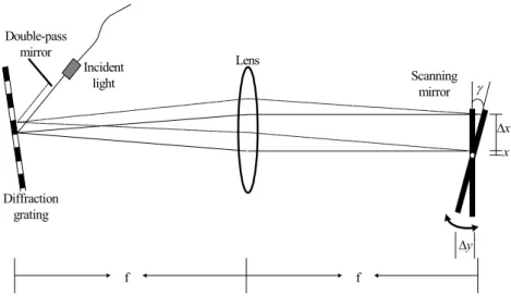
Figure 4. Schematic diagram of the optical phase delay line. (Above view)
6.8 000 0 6.7 500 0 6.7 600 0 6.7 700 0 6.7 800 0 6.7 900 0 1 000 0 0 50010 00 1 500 2 000 250 0 3 000 350 0 40 00 450 0 5 000 55 00 6 000 65 00 7 000 750 0 8 000 85 00 900 0 95 00 Plot 0 Ou tpu t Array 2 (a) (c) (b)
Figure 5. (a) An ideal intensity of reference arm; (b) real intensity of reference arm in OCT constitute by phase delay line; (c) light propagation in sample arm.
Figure 6. Photograph of the probe setup.
the system the axial spatial resolution of the system is thus determined to be 19.4 μm.
The transversal spatial resolution of OCT is determined by the focusing properties of an optical beam.
d
f
x
π
λ
04
=
∆
(2)Note that the spot size of the focused beam is the
minimum spot size that proportional to the focal length f of the focusing lens and inversely proportional to the diameter d of the beam.
x
∆
Probe design
A variety of clinical applications of OCT have been made possible by designing OCT probes. L-shaped probe used a single mode fiber focuser (FF) that inserts into a moving tube (MT) has been constructed. The moving tube was inserted into a stationary one (ST) and then coupled to a stepping motor for lateral translation scanning. Figure 3 is the complete setup of the probe. Fiber focusers with low back reflection, designed to focus light exiting a fiber to a desired beam spot size. The transversal spatial resolution of 20 µm can be achieved [21]. The size of the probe is designed to be used surface of open area especially for oral tissue.
Phase delay line
OCT based on high speed Fourier-domain variable-phase optical delay line provides imaging speed up to video rate [22]. Phase delay line is an effective and popular method for high speed OCT system. Figure 4 shows configuration of Fourier-domain variable-phase optical delay line. It consists of a grating and a lens in folded geometry. Scanning mirror is placed at the focal plane, and then driven by a galvanometer.
J. Med. Biol. Eng., Vol. 23. No. 1 2003 10
Figure 7. Measured signals obtained from a mirror plate as the sample: (a) interferogram; (b) envelope.
(a) (b) (c)
Figure 8. Mirror plane OCT image: (a) the first position in sample arm; (b) the image from second position before correction; (c) after correction the.
In our system, the diffraction grating is 400-lines/mm and the focus length of lens is 10cm. The grating spreads the spectrum of the incident light; first order diffracted light is transformed to frequency domain by lens and incident on the galvanometer-scanning mirror. The scanning mirror produces a wavelength dependent phase shift. The reflected light is inversed Fourier transforms by the lens and re-coupled into the reference arm. The wavelength dependent phase shift in frequency domain corresponds to a group delay in time domain. So, if the mirror is rapidly scanned, a time dependent optical group delay is produced and achieved axial scanning. The mirror scans at 100Hz can achieve 0.9 m per second in our system.
Image Compensation
There are two issues that can influence the returned real sample arm information. The first is in reference arm
constituted by phase delay line. The ideal intensity of reference arm in OCT is shown in figure 5(a). However, the real intensity comes out from reference arm in OCT constitute by phase delay line is shown in figure 5(b), which shows the difference intensity of varied optical delay length in phase delay line. The other issue is depth of focus in sample arm. The light propagation in sample arm is shown in Fig 5(c). The reflective intensity and resolution will degrade when out of focus. The two issues cause the same object at difference sample position arm has different intensity in reconstructed image. To compensate this problem, we propose an algorithm that will restore the issue.
Results and Discussions
The handheld probe is shown in Fig. 6, which is suitable mm In ten sity (V) (a) In ten sity (V) mm (b)
in skin or oral application. Figure 7(a) shows the interferogram and figure 7(b) shows the envelope of inference signal after demodulated. The FWHM of the envelope is the spatial resolution of OCT system. Fig. 8 shows the reconstructed image of reflective mirror. Two different position of mirror in sample arm is shown in Figure 8(a) and 8(b). The discrepancy of intensity between two images is obvious. Figure 8(c) shows the result of reconstructed reflective mirror image after processing by compensation algorithm. Due to lower signal intensity and thus greatly affected by noise, it might thus need a filter or other noise reduction algorithm in the future. The details of reflective layers can be clearly restored as compared to figure 8(a).
Conclusions
A fiber optics based OCT imaging system designed for biomedical application has been build for in vivo scanning skin and oral mucosa applications. The major components of the system include a phase control optical delay line for fast scanning rate, a 2 × 2 fiber coupler, and a L-shaped handheld probe with a stepping motor for lateral scanning and fiber focuser for beam focusing. The optical components are integrated into a computer system that containing detection electronics and data processing.
References
[1] D. Huang, E. A. Swanson, C. P. Lin, J. S. Schuman, W. G. Stinson, W. Chang, M. R. Hee, T. Flotte, K. Gregory, C. A. Pualiafito, and J. G. Fujimoto, “Optical coherence tomography,” Science 254: 1178-1181, 1991.
[2] M. R. Hee, J. A. Izatt, E. A. Swanson, D. Huang, C. P. Lin, J. S. Schuman, C. A. Puliafito, and J. G. Fujimoto, “Optical coherence tomography of the human retina,” Arch. Ophthalmol., 113: 326–332, 1995.
[3] S. A. Boppart, M. E. Brezinsk, B. E. Boump, G. J. Tearney, and J. G. Fujimoto, “Investigation of developing embryonic morphology using optical coherence tomography,” Dev. Biol., 177: 54–64, 1996.
[4] J. Welzel, E. Lankenau, R. Bringruber, and R. Engelhardt Optical coherence tomography of human skin,” J. Am. Acad. Derm. 37: 958-963, 1997.
[5] B. W. Colston, U. S. Sathyam, L. B. DaSilva, M. J. Everett, P. Stroeve, and L. L. Otis, “Dental OCT,” Opt. Express, 3: 230-238, 1998.
[6] Y. H. Zhao, Z. P. Chen, C. Saxer, Q. Shen, S. H.Xiang, J. F. de Boer and J.S. Nelson, “Doppler standard deviation imaging for clinical monitoring of in vivo human skin blood flow,” Opt. Lett. 25: 1358-1360, 2000.
[7] J. A. Izatt, M. D. Kulkarni, Hsing-Wen Wang; K. Kobayashi and M. V. Sivak, Jr., “Optical coherence tomography and microscopy in gastrointestinal tissues,” IEEE Journal of
Selected Topics in Quantum Electronic, 2: 1017-1028, 1996 [8] A. M. Sergeev, V. M. Gelikonov, G. V. Gelikonov, F. I.
Feldchtein, R. V. Kuranov, N. D. Gladkova, N. M. Shakhova, L. B. Snopova, A. V. Shakhov, I. A. Kuznetzova, A. N. Denisenko, V. V. Pochinko, Y. P. Chumakov, and O. S. Streltzova, “In vivo endoscopic OCT imaging of precancer and cancer states of human mucosa ,” Opt. Express 1: 432-440, 1997.
[9] T. Q. Xie, M. L. Zeidel and Y. T. Pan, “Detection of tumorigenesis in urinary bladder with optical coherence tomography:optical characterizaion of morphological changes,” Opt. Express, 10: 1431-1439, 2002.
[10] M. Gupta, A. M. Rollins, J. A. Izatt and I.R. Efimov, “Imaging of the Atrioventricular Node Using Optical Coherence Tomography,” Journal of Cardiovascular Electrophysiology, 13: 95, 2002.
[11] S. Radhakrishnan, A. M. Rollins, J. E. Roth, S. Yazdanfar, V. Westphal, D. S. Bardenstein and J. A. Izatt, “Real-Time Optical Coherence Tomography of the Anterior Segment at 1310 nm,” Arch Ophthalmol. 119:1179-1185, 2001.
[12] A. Gh. Podoleanu, J. A. Rogers, D. A. Jackson and S. Dunne, “Three dimensional OCT images from retina and skin,” Opt. Express, 7: 292-298,2000.
[13] J. A. Rogers, A. Gh. Podoleanu, G. M. Dobre, D. A, Jackson and F. W. Fitzke, “Topography and volume measurements of the optic nerve using en-face optical coherence tomography,” Opt. Express, 9: 533-545, 2001.
[14] X. Li, C. Chudoba, T. Ko, C. Pitris, and J. G. Fujimoto, “Imaging needle for optical coherence tomography,” Opt. Lett. 25: 1520-1522, 2000.
[15] A. M. Sergeev, V. M. Gelikonov, G. V. Gelikonov, F. I. Feldchtein, R. V. Kuranov and N. D. Gladkova, “In vivo endoscopic OCT imaging of precancer and cancer states of human mucosa,” Optics Express 1: 432-440, 1997.
[16] G. J. Tearney, M. E. Brezinski, B. E. Bouma, S. A. Boppart, C. Pitris, J. F. Southern, and J. G. Fujimoto, “In Vivo Endoscopic Optical Biopsy with Optical Coherence Tomography,” Science; 276: 2037-2039, 1997.
[17] Z. Chen, Y. Zhao, S. M. Srinivas, J. S. Nelson, N. Prakash, and R. D. Frostig, “Optical Doppler Tomography,” IEEE J. of Quantum Elec. 5: 1134-1142, 1999.
[18] C.E. Saxer, J. F. de Boer, B. H. Park, Y. Zhao, Z.Chen and J. S. Nelson, “High-speed fiber-based polarization-sensitive optical coherence tomography of in vivo human skin,” Opt. Lett. 25: 1355-1357, 2000.
[19] U. Morgner, W. Drexler, X. D. Kartner, C. Piltris, E. P. Ippen, and J. G. Fujimoto, “Spectroscopic optical coherence tomography,” Opt. Lett. 25: 111-113, 2000.
[20] J. M. Schmitt, “Optical Coherence Tomography (OCT): A Review,” IEEE Journal of Selected Topics in Quantum Electronic 5: 1205-1215, 1999.
[21] T. C. Luo, “Fiber-Optics based Optical Coherence Tomography for In Vivo Oral Tissue,” Master thesis, Graduate Institute of Biomedical Engineering, National Taiwan University, Taipei, Taiwan, 2002.
[22] A. M. Rollins, M. D. Kulkarni, S. Yazdanfar, R. Ung-arunyawee and J. A. Izatt, “In vivo video rate optical coherence tomography,” Opt. Express, 3: 219-229, 1998.
Journal of Medical and Biological Engineering, 23(1): 7-12 12