A Back-to-Back Micromirror Device for Optical Add/Drop
Multiplexer Applications
Y. C. Lin and J. C. Chiou*
ABSTRACTIn this paper, a back-to-back micromirror device fabricated through surface-micromachining and flip chip packaging technologies is developed for optical add/drop multiplexer applications. Pre-stressed beams were designed to elevate micromirror devices after the release and thermal heat-treatment processes. Torsion flexure structure design provides a reliable rotation degree of freedom for micromirror devices. A mechanical stopper was bonded using flip chip packaging on the top of micromirror devices to constrain the popped-up micromirror to obtain precise deflecting angle. Preliminary experiments had demonstrated the feasibility of the micr omirror devices.
Keywords: back-to-back, micromirror, pre-stressed, heat-treatment
1. INTRODUCTION
For a Dense Wavelength Division Multiplexing (DWDM) networking system, Optical Add/Drop Modules (OADM), that play important role both in optical core networks and in regional access networks, are often required for optical communication. The OADM selectively removes (drops) a wavelength from a multiplicity of wavelengths in a fiber, and adds in the same direction of data flow the same wavelength, but with different data content. Through the OADM modules, the specific data or information could be extracted from or carried into the DWDM networking system such that information could be received or transmit among each communication nodes [1].
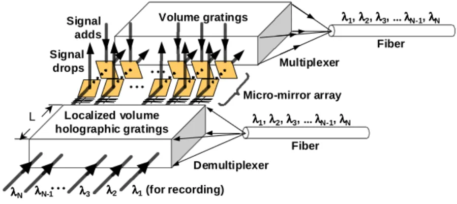
An OADM configuration that integrated volume holographic gratings with MEMS optical switches had been proposed in Fig. 1 [2]. The volume holographic filter with features of narrow-pass-band, high signal-to-noise (S/N) ratio, high insertion efficiency, and compact structure is used to realize DMUX and MUX. The incident lights with different wavelength will be coupled into DMUX and diffracted into designed position through localized multiplexing method. Micromirror array is used to drop specific information or add the desired one into MUX.
Fig. 1 OADM configuration
*[email protected]; phone: 886-3-5731881; fax: 886-3-5715998; Department of Electrical and Control Engineering, National Chiao Tung University, HsinChu, 300, Taiwan
Localized volume holographic gratings Signal drops Signal adds Micro-mirror array Fiber Fiber λλλλ1 λλλλ2 λλλλ3 λλλλN-1 λλλλN
...
...
...
λλλλ1, λλλλ2, λλλλ3, ... ... ... ... λλλλN-1, λλλλN λλλλ1, λλλλ2, λλλλ3, ... ... ... ... λλλλN-1, λλλλN Multiplexer Demultiplexer Volume gratings (for recording) LTo accomplish the task of add/drop function in proposed OADM configuration, an electrostatically-driven micromirror device was designed and developed [2]. The micromoirror devices could be actuated to block or bypass the light signals to extract specific information or add the desired one into MUX. However, the hinge design could not provide the reliable rotation motion as well as the friction wear cause a problem to fabricate the feasible optical switches for OADM applications. In addition, uncertain popped-up angle of the present micromirror devices brings a challenge for the handling of out-of-plane light signals dropped by optical switches or ones that will be added into MUX.
In this paper, a modified back-to-back micromirror device had been developed using surface-micromachining and flip chip technologies to overcome above-mentioned problems. With the similar actuating method in previous design [2], the pre-stressed beams were used to flip up the micromirror devices after the release process. Electrostatic force is applied here to actuate micromirror devices. The torsion flexure design will provide a more reliable rotation degree of freedom than previous hinge design. Thermal heat-treatment method is applied to enhance actuating force. Through the flip chip packaging technology, a U-shape stopper is designed and bonded on the top of the micromirror devices to be the constrain of popped-up angle control. Flip chip bonding with gold bumps had been investigated to gain control of the height of the bonding gap. The accuracy of popped-up angle control and the switching characteristic of the micromirror devices had been measured.
The paper is organized as follows: Section 2 introduces the designs and fabrication of modified micromirror devices. The basic concept of mechanical stopper designed to constrain the popped-up micromirror devices is introduced and discussed in section 3. The investigation of flip chip packaging will be also provided. The preliminary results including angle-control precision and dynamic characteristics of the fabricated optical switches are measured in section 4. Final discussions of present accomplishments along with future works are given in section 5.
2. THE DESIGN AND FABRICATION OF MODIFIED MICROMIRROR
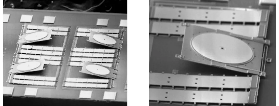
Fig. 2 shows the SEM pictures of the released back-to-back micromirror devices. An optical switch consists of a micromirror (300μm in diameter), four pre-stressed beams (350μm in length, 70μm in width), and torsion flexure design to provide rotation degree of freedom. The devices were fabricated through Poly-MUMPs process provided by Cronos Integrated Microsystems [3]. The 0.75um oxide layer (PSG2) was trapped between two polysilicon layers (Poly1 and Poly2) to minimize warpage of the mirror surface. The metal layer (Gold) is deposited on the center of mirror to obtain high reflect efficiency. Four pre-stressed beams connected in parallel are designed to provide more actuating force to flip up the micromirror devices. After the HF release process, the back-to-back micromirror devices will be flipped out of plane to have an initial popped-up angle. Electrode (substrate) under the pre-stressed beams is designed to apply electrostatic force to actuate the micromirrror devices. However, the initial popped-up angle of the micromirror devices could not meet the requirements of proposed OADM configuration. The light signal output from DMUX could not be dropped completely since the popped-up angle is smaller than 45 degree. Also, the micromirror could not accomplish to add selected signal into MUX.
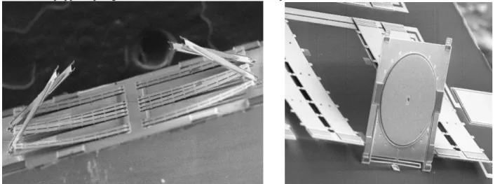
To enlarge the popped-up angle of the micromirror devices, the actuating force of the pre-stressed beams must be improved. Here, we introduced the thermal heat-treatment method [4] to accomplish this task. After the release process, the mirror chips were put on the hot plate that will be heated to about 140OC for required heat treatment. After the thermal heat-treatment of the pre-stressed beams, the micromirror devices will be flipped up to have larger popped-up angle than the initial one. Fig. 3 demonstrated the results after the thermal heat-treatment process. It is clearly to show that the popped-up angle of micromirror devices had been improved.
Fig. 3 SEM pictures of released back-to-back micromirror devices with thermal heat-treatment
Thermal cycling response of layered gold/polysilicon microstructures had been investigated [4], however, stress induced during heating process is difficult to control since it depends on the manufacturing process directly. It indicated that actuating forces of the pre-stressed beams might be different and unpredictable for each fabricated micromirror devices. As a result, the popped-up micromirror devices will not reach identical angle, which also brings a problem to integrate the fabricated micromirror devices with volume holographic gratings. To overcome this, an approach to fabricate mechanical stopper to constrain the popped-up micromirror to have desired angle is proposed here. The flip chip packaging is applied to realize this concept. The basic concept and process are given in the section 3.
3. FLIP CHIP PACKAGING
Flip-chip packaging had been developed to many MEMS designs in the last decade [5-6]. It is frequently used to transfer MEMS structures to other substrates that provided MEMS designers a new capability to integrate different structures and substrates. In this paper, the flip-chip packaging process is applied to obtain precise angle-control of the popped-up micromirror devices to overcome above-mentioned problems. Firstly, a mechanical stopper is bonded on the top of micromirror devices. After the release and thermal heat-treatment processes, pre-stressed beams are able to have enough actuating force to flip up micromirror devices to reach the mechanical stopper. The stopper will constrain the micromirror devices at the desired popped-up angle. Therefore, the popped-up of the micromirror devices could be controlled precisely.
3.1 THE DESIGN OF MECHANICAL STOPPER
The conceptual design of mechanical stopper is illustrated in Fig. 4. Pre-stressed beams flipped up the micromirror device after the release and thermal heat-treatment processes. However, the mechanical stopper bonded on the top constrains the micromirror device at designed deflecting angle. The well-controlled bonding gap provides the precise deflecting angle of the popped-up micromirror device. The relation is given by
l
h
1sin
−=
θ
(1)where h is the bonding gap, θ is controlled angle, and l is the length of the micromirror device.
h
θ
l
stopper
mir
ro
r
Fig. 4 Conceptual design of mechanical stopper
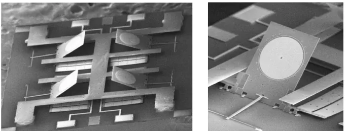
A top-plate with U-shape stopper fabricated through MUMPs was developed to bond with the micromirror devices for realizing this conceptual design. The design of U-shape stopper is used to prevent blocking of the light signals. Consider the configuration in Fig. 4, if a non-transparent substrate is bonded on the top of the micromirror device as the stopper, the light signal output from DMUX could not pass through the top-plate as well as the selected light signals that should be added into MUX shown in Fig. 1.The bonding was performed using flip chip bonder developed by CAMPmode, University of Colorado at Boulder [7]. Fig. 5 shows the SEM pictures of fabricated back-to-back micromirror devices with mechanical stopper. It is clearly to see that the micromirror device had reached the desired angle since it touches the mechanical stoppers.
Fig. 5 SEM pictures of fabricated back-to-back micromirror devices with mechanical stopper
3.2 INVESTIGATION OF FLIP CHIP PACKAGING
To obtain well-controlled bonding gap h to reach precise popped-up angle θ, the flip chip bonding using gold bumps was performed to examine its corresponding reliability and repeatability. Fig. 6 shows an example of the completed flip-chip bonding micromirror device. The joint height of the bonding gap is related directly to the bonding forces with the same bonding temperature (140 OC). The load cell located on top the flip chip bonder is used to control bonding forces during the bonding process. The joint height was recorded with the same bonding environment. Table 1 presents the measurement results of the joint height for several fabricated micromirror devices with the same bonding conditions. The results showed that the relative errors of the joint height are both within 1%. Experimental results indicated the repeatability in controlling accurate joint height using flip chip bonding is both feasible and reliable.
h 15 20 25 30 35 40 0 2 4 6 8 10 12 14 16 Bonding Force (lbs) Joi n t he ight ( u m ) Bonding Accuracy: +/- 1% h 15 20 25 30 35 40 0 2 4 6 8 10 12 14 16 Bonding Force (lbs) Joi n t he ight ( u m ) Bonding Accuracy: +/- 1%
Fig. 6 Joint height vs. bonding force of flip chip bonding (with gold bumps at 140OC bonding temperature)
Table 1 Bonding characteristics with gold bumps
4. EXPERIMENTAL RESULTS
With the fabricated micromirror device, the characteristics of the device need to be investigated. The accuracy of the popped-up angle of the micromirrors during the ON/OFF stage of the applied electrostatic force is measured. Fig. 7 illustrates the optical configuration to measure the popped-up angle of the fabricated micromirror devices. The laser is manually aligned to the popped-up micromirror until the path of incident light reflected from the rotation mirror and reflected light from the micromirror is the identical one. This implies that the popped-up angle of the micromirror (θ) is equal to two times of the tilting angle of the rotation mirror (ψ). Table 2 lists the measurement results of three fabricated micromirror devices In comparison to the proposed 45-degree popped-up angle for the OADM configuration, the relative error is within 1.6%, which shows the capability of the present assembly method in controlling the angle of the micromirrors.
Finally, Fig. 8 shows the results of dynamic characteristics of the fabricated micromirror devices. The ON/OFF states of the optical switch were tested. The switching speed had been demonstrated to reach 100Hz. The electrostatic pull-down voltage of the pre-stressed beams is about 100V.
Gold Bump
Temp: 140degree
Force: 8lbs
Time: 3 seconds
29.9um
30.5um
30.2um
Device 2
Device 3
Bonding Environment
Device 1
Gold Bump
Temp: 140degree
Force: 8lbs
Time: 3 seconds
29.9um
30.5um
30.2um
Device 2
Device 3
Bonding Environment
θ
ψ
fixed mirror
rotation mirror
optical switch
laser
θ
ψ
fixed mirror
rotation mirror
optical switch
laser
Fig. 7 Optical configuration to measure the popped-up angle of micromirror devices
Popped-up angle measurements
44.3
°45.3
°45.2
°44.6
° Device 4 Device 3 Device 2 Device 1Popped-up angle measurements
44.3
°45.3
°45.2
°44.6
° Device 4 Device 3 Device 2 Device 1Table 2 Popped-up angle measurement results of fabricated micromirror devices
(a) On state (Micromirror is pulled down) (b) Off state (Micromirror is popped up) Fig. 8 Dynamic characteristic of the fabricated micromirror devices
5. CONCLUSIONS
In this paper, a surface-micromachined micromirror devices had been developed using Poly-MUMPs and flip chip technologies. The prestressed beams were designed to elevate micromirror and electrode (substrate) under the pre -stressed beams is used to actuate micromirror devices to reach add/drop light signals in the designed OADM system. Flip chip packaging technique is adapted to control the popped-up angle for precise switching of the proposed OADM configuration. Experiments had indicated the micromirror devices could be controlled to achieve required popped-up angle using the proposed processes. The dynamic characteristic of the fabricated micromirror devices was also investigated. Finally, a reliable back-to-back micromirror device for proposed OADM configuration is obtained.
Driving Signal Driving Signal
Optical Response Optical Response
ACKNOWLEDGEMENTS
The authors would like to thank Prof. Y. C. Lee’s and Prof. V. M. Bright’s research group at the Department of Mechanical Engineering, University of Colorado at Boulder, for the supports of flip chip packaging and measurement. This research is supported by National Science Council of ROC (NSC91-2215-E-009-028) and Lee and MTI Center for Network Research of National Chiao Tung University in Taiwan.
REFERENCES
[1] S. V. Kartalopoulos, Introduction to DWDM Technology, SPIE, New York, 2000.
[2] J .C. Chiou, Y. C. Lin, S. D. Wu, and S. H. Lin, “MEMS -based Micromirror Device for Optical Add/Drop Module”, SPIE MICRO/MEMS’01, Dec., Adelaide, Australia.
[3] D. Koester, R. Mahedevan, B. Hardy and K. Marcus, “MUMPs Design Handbook”, rev. 7,
http://www.memsrus.com/, 2001.
[4] Ken Gall, M. L. Dunn, Brian Corff, and Yanhang Zhang, “Thermal Cycling Response of Layered Gold/Polysilicon MEMS Structures”, 2001 Mechanics and Materials Conference, 2001.
[5] Ronda Irwin et al, “Quick Prototyping of Flip Chip Assembly with MEMS”, Proceedings of the 1998 IEEE Radio and Wireless Conference (RAWCON `98), Colorado Springs, CO, pp. 293-296, August 9-12, 1998.
[6] J. C. Chiou, Y. C. Lin and S. D. Wu, “Closed-loop fuzzy control of torsional micromirror with multiple electrostatic electrodes,” IEEE/LEOS International Conference on Optical MEMS, 2002, pp85-86.
[7] Refer to Department of Mechanical Engineering, University of Colorado at Boulder, USA, http://mems.colorado.edu.