A
Vision-Based Vehicle Behavior Monitoring
and
Warning
System
Tang-Hsien Chang, Chun-hung Lin,
Chih-sheng Hsu,Yao-jan Wu,
Abstract-This paper outlines the approach to restrain the transportation (or car) accidents caused by dangerous vehicle behaviors. especially those of lane departure and speeding. Based on the proposed approach, the possibility of cnr collision is reduced by an equipped in-vehicle vision-based system that monitors the sight in front of the car and issues certain necessary warning. Meanwhile, the infrastructure of monitoring and warning system as well as related image processing techniques is proposed. Furthermore, an application for decision model to launch warning is also discussed herein. Finally, the proposed approach is validated in real road tests.
Index Termr-Digital Image Processing, Monitoring, Vehicle Behavior. Warning
1. INTRODUCTION
n past decade. the number of motor vehicles in the
I
developing countriesis
increasing gradually [I]. The official investigation reports of traffic accidents point out those dangerous driving behaviors, suchas
drunk and drowsy driving, have taken a high proportion among all the accidents causes. In order to avoid this kind of unexpected accidents. itis
necessary to developan
appropriate set of in-vehicle detecting and warning systems that can directly improve the driving safetyHowever. several complicated issues are invoived with keeping an eye on drivers directly all the time to wipe out all possible hazards
[Z].
In fact. human behaviors are indeed hard to recognize. predict and handle by current available equipments. Therefore: a monitoring and warning system focusing on the vehicle behaviors is needed while the car ismoving on the road. Vehicle behaviors include moving track
Tanphsien Chang is wirh Division of Transpanation. Department of Civil
Enzineenng. National Taiwan University. Taipei 106 Taiwan (e-mail: [email protected]).
Chun-hung Lin wm with Computer-Aided Engineerinz Croup. Depanment of Civil Engineering, National Taiwan University, Taipei 106 Taiwan. He is now with Division of Transpanation. Department of Civil Engineering, National Taiwan University (e-mail [email protected]).
Chih-sheng H w is wilh Division of Transpanation. Deparunenl of Civil Engineering, Naianal Taiwan University. Taipei 106 Taiwan (email: NOS2 [email protected]).
Yao-;an Wu is with Division of Tmsponatian. Dcpanment of Civil Engineering. National Taiwan University, Taipei 106Taiwan (corresponding author 10 provide phone: t886-2-2362-5920 ex1 402;. fax: ~886.2-2363-99W;e-mil: NI 5215098nru.rdu tw)
0-7803-8125-4/03/$17.00 0 2003 IEEE
I M o n , l o " " , d Y i * i ~
c _ _ _ _ _ _ _ _ _ _ _ _ _ _ _ _ _ _ _ - _ - ~
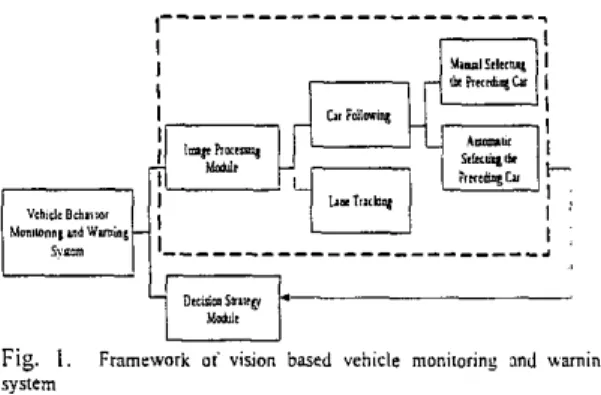
Fig. 1. Framework oi vision based vehicle monitoring md warningsystem
and speed. and those could reflect the potential dangers briefly.
For some practical conditions. the experimental scenario should be constrained tu concentrate on freeway and express way. Atter shooting the sight right in front of a vehicle. the image processing equipments are abie to get the moving track relative to the lane and vehicle speed relative to the obstacles (e.g. the other preceding cars). In accordance with ail
necessary information from image processing, the decision strategy composed of " F u w Neural Networks" could identify whether the vehicle is about to depart the lane or coliide with anything ahead. Imape processing and decision making mode1
are
combined to build a real-time monitoring mechanism. The system framework is shown in Fig. I .Nowadays, ITS (Intelligent Transportation System) has been developed successfully in many countries. Among the developing processes, there is
a
systemized project called the"ASV" (Advanced Safety Vehicles). The ASV system could aim at all the potential cmses, including mechanical and human factors that might result in traffic accidents and address to research the hardware and sofnvare facilities that are useful for prevention and improvement. In Taiwan, there are
an
immediate need to develop the ITS industry and lots of relevant system frame:vorks.
11. SYSTEM OVERVIEW A. Requiremenis of Hardware
To collect the real-time circumstance in front of the experimental vehicle, a CCD camera
is
installed on the central top of the dashboard. In the experimental procedure, ail the input data and computerized modules are handled in a standard Pentium computer system [3]-[5]. Besides, a portable notebook is used to aid for the convenience and efficiency tocorrect the p r o b m at any time. The flowchart as shown in
F i g 2 illustrates how the whole system is designed to operate.
I I I
‘I
3 1 I (rI
I R e a l T i n e Datai
, I D a a Reouired-
Strategy and I ’- . UOdeI~,-I
, .. I II
I
E. Requiremenls ofSofnsureThere are several software necessities for the drowsiness warning system.
I ) Data detecting and processing
is
in charge of receiving the information captured from theCCD
camera. Analyzing effectively and graphing the moving curve will be helpful for establishing the threshold.2) According to the data updated from the image processing,
the decision algorithm composed of the “Fuzzy Neural Networks” is in charge of determining whether a vehicle comes out
a
dangerous behavior ornot. It
not only concludes “yes” or “no”, but also separates the conclusion into different levels and makes proper wamiog.3) The warning device is responsible for launching alarm
mechanism after the behavior decision model detects any danger. In order to monitor on-line the different waming levels, the driver software should send different request impulses according to one specific timing period to initiate a
practical ivaming.
Ill. IMAGE PROCESSING MODULE
In order to obtain meaningful information
from
continuous image shots right in front of experimentally tested vehicle as the input of decision module, we must utilize the advantage ofimage processing techniques to get the data needed, such as
the relative distance and relative speed between the lane markings and the vehicle and the vehicle as well as the relative distance and speed between preceding
car
and obstacles. Asa
result, there are two subsystems included in the image processing module to help us extract information and provide data to decision module.
A . Lnne trucking system
The main goal of the lane tracking system is to find the car trajectory within lane. Hence, lane marking in the whole image is not necessary as proposed by other studies [6]-[10]. The procedures for lane tracking are described
as
follows:I ) Define Searching Range. There is too much information contained in one image. Hence, it
is
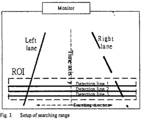
impossible for the lane tracking system to process all images simultaneously because one image contains too much information for real-time processing. To overcome this drawback, a portion of the original image, called Region of interest, ROI [IO], is first defined. As shown in Fig 3 (I don’t see Fig.3).
the y-axisis
the time axis and its positive direction denotes the heading direction of the experimental vehicle. The x-axis
is
the searching axis and the origin is the center of ROI.2) Adaptive Thresholding. Suppose that the gray-level
histogram corresponds to ROI, composed of light objects on a dark background. In this way, the gray level of these objects and background pixels can be grouped into two dominant modes. As a result an excellent algorithm for thresholding plays an important role in image segmentation. In this case, we have to extract the lanes (light objects) appearing in the image captured. Owing to changeable scenes occuning frequently, the distribution of the gray-level histogram may be changing with time. This kind of uneven illumination can cause pre-defined threshold \,slue fail to handle this kind of situation. However, we use the statistical property of image and view every gray-level histogram of image frame as a
normal distribution. In the most cases, the light parts (e.g.
lanes) are over the 951h percentile of the distribution when the threshold value is set.
5) Set Up Detection Line: Within the ROI, we can set up three detection lines to search for the lanes n e a the middle of
the ROI. If the positions of lane markings are located, we compute the mean value of the x coordinates ofthese two lane markings and represent it
as
the car moving trajectory data thatare
funher
usedin
the decision
moduleof
this
system.
The computation can eliminate the effect of vibration caused by the moving car. Assume that we can always find the lanes successfully. A moving trajectory found by this module can be easily established and stored in
a
database of the system that other compqter program could restore them when needed. However, it is infeasible to find continuous lane markings continuously because some lane markings on the road are from broken lines. In this study, this kind of problem can be solved by means of either parameter estimation technique suchas the one described in 4) or using other programming tricks to construct the continuity of lane tracking.
4) a-P filter: If the line detection algorithm mentioned above does not find any lane markings near the middle of image, the system might fail .In order to make up this kind of
thresholding failure, a modified filter, called
a-P
filter,is
added into the system to provide the ability of reconstructing the trace of lane tracking.
5 ) Simulation: the system has been tested on many
circumstances successfully during the day. It proved that this lane tracking system is reliable. One pair of the test results are
as
shown in Fig. 4 and Fig. 5 .Monilor
I
r
I1-
_ - - - - + - - - I I I - - - + e * a o s,
Fig. 3. Setup of searching range
B. Preceding Car Tracking System
In this part,
a
vehicle tracking system basedon
video images is developed to track the preceding vehicle while following. The system can determine the coordinates of the preceding vehicle in video images, measure the distance between the preceding vehicle and the following one. and calculate the relative speed. The information resulting From the system can be used in a driver assistant warning system in the next section. The main subsystems for the vehicle tracking system are vehicle selection, template matching, relative distance and speed measuring, and fuzzy a-p filter [l I].I) Pre-processing: The strategy for vehicle selection is based on the fact that vehicle images have strong horizontal and vertical edges. The main algorithms for the automatic vehicle selection are (a) denoising, (b) Sobel edge detection, (c) generating the edge histograms.
2) Vehicle Selection:
In
this research, we divide vehicle selection procedure in two subsystems. One of them is anautomatic vehicle selection subsystem. In this system, the computer would decide which car in the image
is
most threatened. Moreover, the computer automatically picks it up and updates the most threatened car to computer; the other subsystem is a manual vehicle selection subsystem. After the user clicks on the target vehicle and inputs a set of coordinates (x, y), the system will find the nearest two vertical edges basedon a pre-defined threshold of vertical edge strength and the vertical edge histogram. The horizontal edges in this region are summed to form the localized horizontal edge histogam. These two edges correspond to the two vertical boundaries of the target vehicle. This computation will reduce the noise in
the original horizontal edge histogram and reveal the peak value corresponding to the vertical boundaries of the target vehicle. Finally, range of the desired vehicte can be
P
determined, and the template used in the vehicle tracking system
is
generated.3) Tracing Strategy and Algorithm: In this study, we wiil apply the template matching method to be the main algorithm in the vehicle tracking system. This method compares the sequence of the pixel value in both the template and the matched region in the image to determine where the target is. The template image is the image of the target the car needs’to track.
In
the system, the symmetr,ic,property of the preceding vehicle in the image is also considered for improving the tracking accuracy. The predicted location by a robust algorithmis also
used to improve the accuracy of the template matching system.Fig. 5 . Relative lateral speed
Symmetric reduction factor, distance-based reduction factor, searching range, and threshold of the correlation coefficient are the four parameters of the proposed system. The correlation coefficient
is
used to quantize the similarity of the matching. The correlation coefficient ( p ) is defined by the following equation:Another initialization is needed when determining the searching m g e used to reduce the computing time
as
the system searching for the target in the image. Chiu [I21suggested that the searching range be set to three times of
standard deviation of the center coordinate to increase the processing speed, but this would result in failure when the preceding vehicle s n i t s to tum. The default searching range is set to 20 (horizontal direction) x I0 (vertical direction)
pixels. This setting works properly in most environments except some heavily sh&ing environments. In this research, the system will compare the summation of the pixel value of
the left half and right half matched region of the image to determine whether the portion is mirror symmetric. If the difference of the W O summations
is
greater than a given value (in this research, the value is set to 3.5 % o f the pixel value summation of the matched region), the correlation coefficient calculated at that position is reduced by a reduction factor.In this research. the reduction factor is 0.92 because the successfully matched coefficient is usually greater than 0.92.
One of the improvements of the template matching method
in this research is the symmetric concept. This concepr comes from the observation of road vehicles that their back view is almost mirror symmetric for the most part. Another improvement is the distance-based reduction factor. This is based on the predicted location o f the preceding vehicle in the image plane. The reduction faction is obtained from a Gaussian function whose input is the distance from the predicted location to the matched location. The Gaussian hnction is the same as the following equation:
- x -
-
G(.~,u)=e'."'
(2)This reduction factor is in the range [O. I]. Because the prediction from the robust system is not accurate enough aiier one missing irame. the reduction factor is not applied a h e n the last matchinp has failed.
4) Measurement of Relative Distance and Speed from License Plate: This method
is
basedon
the input image used by the trackins system. Several image processing techniquesare applied IO find the location of the license plate of the preceding vehicle. The image size of the plate is also obtained by the region growing technique. Using the geometric relation the relative distance can be calculated. The primary restriction of this method is that the color of the preceding vehicle has to be dark to make the white license plate obvious in the image.
The procedures ofthis method can be divided into two pans in this system. First. the system identifies thr location of the license plate in the image. Second. the system calculates the image size of the plate. In this research. we assumed that the background of the license plate is white and the preceding vehicle is dark. With this assumption. the location 01' the license plate c m be identified by selecting the brightest pixel in the center region ot'the template image. This pixel is used
as
the seed in the region growing method and use some constrains to locate the plate (e.g. ratio o f width of the real plate and width ofplate in the image).The method described in this section is implemented in the tracking system successfully in many situations. such
as
sunny day, rainy day, night and etc.5 ) Vehicle Motion Prediction Using Control Theory: Many
tracking systems adopt control theory to make their system more reliable and to reduce the noise while tracking. Control theory can also be used to predict the tracking result at the next scan.
To
simplify the computation, the relative distance calculated by the method described in the previous section can be filtered by theU - 8
filter that can reduce the noise and make the result more accurate. The relative speed can also be derived by the filter.6) Simulation: The system with single template matching method is tested in eight scenarios including daytime. night, rainy day, street, night and mountain road, and entering and exiting
a
tunnel ona
freeway. The vehicle tracking system works successfully in the most given scenarios with frame rateIO
fps, and the probabilities of success are above 95.65%.The relative distance and speed measurement system works properly in the four tested scenarios. and the probabilities of plate detection are all above 91.88%
[v.
DECISION STRATEGY MODULEWhen a car is moving on a highway, the general situation is
illustrated in Fig. 6. Initially, the data gathered
rim
the image processing include two major referable objects: I ) tk lammarks, 2) the obstacle ahead of the esperimental vehicle. In
the first one, the lateral relative speed and displacement from the experimental vehicle are calculated by the image processing. Simultaneously. the longitudinal relative data in
the second one would be obtained by the same way.
Fie. 6.
be lane murkr. W the vehicle width, Y : the lateral displarcmcnt Concept ofthe relative position afthc experimenrai vehicle and
A. Composiiion ofDecision Sfroregy
In this study, the primary decision method is relying on "Radial
Basis
Probability Network" (RBI"), one certain kind of "Neural Networks" [ I I]. Assuming that there is a vehicle under normal control. hence its moving behavior could beregarded as a relative stable wave line, as shown in Fig. 7.
However. the vehicle might be judged
in
dangerous situation while the moving track becomes an unstable vibration curve. This module can distinguish the difference between lane changing and lane departure, and additionally. to recognize what kind of state the experimental vehicle is staying in, i.e.. "safe", "caution": or "danger".On
the other hand. to prevent the collision with any steady or moving obstacle. a mechanism about keeping safe space and speed is required. Therefore, the RBPN is applied to determine the classifications of the above real time consecutive situations. Besides. the Fuzzy Theory would be used to aid the decision to make it more reliable and reasonable.Fig 7 Conccp ofthe vehicle moving behavior
E. Crirerron ofDecision Srrarep
According to the purposes described previously, the decision module needs several parameters
as
inputs. Ona
highway. in fact. there must be a lot of variables while the vehicle keeps moving on. One of the merits of Neural Networks
is
that it is a proper method to find out some conclusion with lots of potential reasons that are neither recognized nor signified originally. For general situationson
highway and expressway, there
are
a few parameters for input and the notations are shownas
following.w
:Y
:L
:V
:v
: U :N
:the width of the experimental vehicle
the lateral displacement from the center of the vehicle to the lane
the longitudinal distance from the preceding vehicle or obstacle to the expenmental vehicle
the traveling speed ofthe experimental vehicle (i.e., absolute speed)
the relative speed between the preceding and experimental vehicles
the lateral speed that the experimental vehicle gets approaching to the lane edge
the number of the patential dangerous objects appear
in
the scene ahead of the experimental vehicle (i.e., preceding vehicles and obstacles).Fig. 8. Lane Determination zones resulted from "Radial Basis Piobabilin. KerworL" (RBPNI
In
accordance with the principle of Neural Networks, all the variables mentioned above should be collected then receivedas
input layer to train the RBPN. Before practical experimentson the highway, for the necessary networks training, a set of
pre-recorded video files are applied to get the priority data. Technically, the more input training, the more precise determination is coming out. RBPN is able to find out several conspicuously effective parameters, i.e., the factors or variables in real situation. The lateral displacement
( Y )
and the lateral relative speed ( U ), for instance, are the obvious parameters to evaluate the probability of lane departure. According to these results of processing the images and data; it could generally classif?. the decision zones by applyingREPN,
as
shown in Fig. 8. From light to dark, it says that more lateral displacement and higher lateral speed will lead to lane departure more posnibl?..Based
on
the determination zones, consequently, the warning mechanism is going to take effect as follows:0 White zone: Safe and not to launch any warning. 0 Gray zone: Make certain moderate caution, e.g., blink 0 Dark zone: Cany out warning signal immediately,
On the other hand, it is not easy for the module to exactly determine whether the experimental vehicle is approaching or belongs to the dangerous zone while there is some saw-toothed edge between different
zones.
With regard to the mechanism
of
avoiding car collision, itcould be settled by the similar RBPN module to determine whether the vehicle needs to decelerate or not [121. A
I-dimension probability distribution is built up in front of the vehicle. Depending on the module of automatic selecting preceding car, the number
of
the preceding vehicles and obstacles could be collected. And that is a conspicuously effective parameter for car collision avoidance.signal light. e.g., voice alarm.
V. CONCLUS~ON
In fact, there are a lot of complicated and changehl states out of vehicles on the highway from time to time. That is a workable way to collect the information as much
as
possible by image processing. However, to analyze the actual situation clearly is nota
simple task. Radial Basis Probability Network (RBPN), a kind of Neural Networks. is appropriate to deal with such a scenario with so many variables and uncertainties. Going through the image processing could reflect the general vehicle behavior on the highway. Meanwhile, a8er the module training and simulating, it is able to determine which danger level the moving vehicle is standing in. T h e results obtained from the pre-recorded data and simulation system are acceptable and successful, and at this moment, the field experiment has already started. The simulation system with continuously programming and correcting would satisfy the practical experiments then. After that,a
complete vehicle behavior monitoring and warning systemas
ASV tool is going to be establishedREFERENCES
[I] lniiiiute o i Tranrponnion. M i n i r q of Transpaitation and Cammunieeionr. R.D.C., Dercmon md Collecmm of Tm@ InJbrmurron (In Chinese). 1996.
M. Enkrson. N.P. Pavanikalopoulos. "Diver fatigue : a viriowbared (21
131 S. Lee. W. Kwon. I.W. Lee. " A Vision B a d Lane Depanure Waming
System (Pierented Conference Paper rtllel." presented at me IEEUSRJ lntemational Conference on Intelligent Robots and Systems. 1999 pp. 160-165.
W. Kwon. J.W. Lee. D. Shin. K. Roh. D.Y. Kim. S. Lee. "Experiments on Decision Making Strategies for B Lane Depmnure W m i n g System (Presented Conference Paper rtylel," presented at the IEEE Inlemational Conference an Robotics & Automation. Detroit MI. USA. May 1999. pp. 2596.2601
R. Rilwck. N. Mohlcr. W. Enkelmann. " A Video-baed Lme Keeping AsSiSWnt (Prewntcd Conierence Paper s~yle)." presented at the IEEE
Intelligent Vehicles Symposium 1000. D e m b m . MI. USA. October 3.5, 2000. pp. 356-361
[6] M.Bcnolu. A.Bropi. A. Fscioli. A.Tibaldi. " A n Evolutionq Approach to Lane Markings Detection ~n Road Envimnmena." [AJ
(jf
Univerriw di Parmr 2003
171 T. 110. and K. Yamadz "Prccedq Vehx!e md Road Lanes Recognition Methods for RCAS Using Virion System." piesenled JI lhhr Proceedings oithe lntclligent Vehicles '94 Symposium. Puis. France. October 24-26, 1994. pp. SS-90
I. B. McDonald. 1. F r w and R. Shoncn "Application of Hough Transform to Lane Detecttan in Motorway Divtng Scenarios." Signolf & Synem Group. Depanment of Computer Science. National UniverslN
of Ireland. Maynoath. Ireland, 2M)Z.
S. Lee. W. Kwon. D. Shin. D. H. Lee. "Automatic Lane Following with B Single Camera," presented at !he Proceedings of the IEEE hiematianal Conference on Robotics and Automatian. Leuvcn, Belgium. May 1998. '
[ I O ] S. G. Jeang. C.S. Kim. D.Y. Lee. S.K. Ha. D.H. Lee. M.H. Lee, and H.
Hashimoto. "Real-time Lane Detection for Autonomous Vehicle." presented at lhe Proceedings of IEEE lntcmalional Sympiium on Industrid Elcctmacr. Puran. Saulh Korez June 12-16.2001. vol. 3. pp. 1466 -1471.
[I I ] Lin. Chun-Hung. "Fisedins Vehicle T m k i n g Using Image Processin%." M.S. thair. Dept. Civd Eng.. Taiwan Univ.. Taipei. [8]
191
1131 H. C. Lo. Nrurd Nerworkdpplrcotion of h.lurlub (In Chinese). Taipei, Taiwan, ch. 7-8.2001
[I41 P. Seiler. B. Sang. I. K. Hedick, "Developmen of a Collision Avoidance System." Society of Automotive Engineers. Inc.. University
of CJifomia-Berkeley. 1998.
Tang-Hsien Chang was born in Hualien, Taiwan, JanSth,
1954. He received the B.S. degree in statistics from National
Cheng-Chi University, Taipei, Taiwan, 1976, the M.S. degree
in civil engineering from National Taiwan University, Taipei, Taiwan, 1978, and Ph.D. degree from National Taiwan University, Taipei, Taiwan, 1986.
He is currently
a
Professor of Civil Engineering Department at National Taiwan University. His major field is related to Intelligent Transportation Systems.Chun-hung Lin was born in Taipei, June 22nd. He received the B.S. degree in civil engineering from National Taiwan University, Taipei, Taiwan, 2000, and the M.S. degree in civil engineering t o m National Taiwan University. Taipei, Taiwan,
2002.
Chih-sheng Hsu was born
in
Taipei, Taiwan. Sep. 17th, 1977. He received theB.S.
degree in civil engineering from National Central University, Taoyuan, Taiwan, 2000. He is now studying for the M.S. degree in civil engineering at National Taiwan University, Taipei. Taiwan.Yao-jan Wu was born in Taichung, Taiwan. Oct. 2lst. 1979. He received the B.S. degree in civil engineering from National Central University, Taoyuan. Taiwan, 2000. He is now
studying for the
M.S.
degree in civil engineering at National Taiwan University, Taipei, Taiwan.Taiwan, 5 0 2 .
[I21 Chiu. W.C. "Tracking ,he Tmnslarion of rhs Preceding Vehicle Image While Fallowing,: M.S This Dept. Tranrponatian Management, Tamkans Univ. Taipei, Taiwan.