一個增進無線網路服務品質之有效的頻道切換機制
61
0
0
全文
(2) 一個增進無線網路服務品質之有效的頻道切換機制 An Efficient Channel Switching Mechanism for Improving Quality of Service (QoS) on Wireless Network. 研 究 生:許銜書. Student:Hsien-Shu Hsu. 指導教授:陳耀宗 教授. Advisor:Prof. Yaw-Chung Chen. 國 立 交 通 大 學 資 訊 工 程 系 碩 士 論 文. A Thesis Submitted to Department of Computer Science and Information Engineering College of Electrical Engineering and Computer Science National Chiao Tung University in partial Fulfillment of the Requirements for the Degree of Master in. Computer Science and Information Engineering June 2005 Hsinchu, Taiwan, Republic of China. 中華民國九十四年六月.
(3) 一個增進無線網路服務品質之有效的頻道切換機制. 研究生:許銜書. 指導教授:陳耀宗. 國立交通大學資訊工程學系. 摘要 隨著無線網路的發展越來越迅速,越來越多的使用者透過無線網路使用各種不同的 應用服務,而通常使用這些服務都需要品質的保證。然而,現在的無線網路並不能夠有 效的提供這樣的保證。因此,我們提出了一個頻道切換機制來增進無線網路的服務品質。 通常使用者會選擇訊號最強的基地台連上無線網路。但基地台的訊號強度不代表它 可以提供使用者所需要的服務品質。因此,如果我們需要更好的服務品質,就必須要切 換到另一個頻道的基地台,並且嘗試是否有更好的服務品質。然而,如果使用者無法聽 到其他基地台的訊號時,他只能自行移動自己的位置去尋找其他的基地台。在不需要移 動位置或自己一個個嘗試基地台的情況下,我們提出頻道切換機制來解決這個問題。這 個機制可以幫助使用者自己或他人切換到合適的基地台,以便得到服務品質的保證和基 地台之間的負載平衡,. i.
(4) An Efficient Channel Switching Mechanism for Improving Quality of Service (QoS) on Wireless Network. Student: Hsien-Shu Hsu. Advisor: Prof. Yaw-Chung Chen. Institute of Computer Science and Information Engineering National Chiao Tung University. Abstract As the development of wireless network grows faster and faster, there are more and more users using various kinds of applications and services via the wireless network whereas most of these applications and services require the guarantee of the quality of service (QoS). However, the wireless network currently deployed cannot provide any guarantee of the QoS effectively. Therefore, we propose a channel switch mechanism to improve the QoS on wireless network. In most cases, the users may connect to the network by choosing the access point that has the strongest signal. However, the signal strength does not correspond to the quality of service it could offer to the user. Therefore, if we need better QoS, we must re-associate with other access point and try to discover whether the provided QoS is better. Unfortunately, if there are no other reachable access points, the client must move itself to other places to find other access points. To solve this problem, we propose a channel switching mechanism to avoid unnecessary movements or trial-and-error approach to find access points manually. This mechanism effectively helps the users to switch to the proper access points automatically and achieves the load-balancing among the access points to guarantee the QoS.. ii.
(5) Acknowledgement I sincerely appreciate the guidance and the encouragement of my advisor, Prof. Yaw-Chung Chen. He encouraged me in exploiting research topics freely and enthusiastically helped me. Without him, I cannot complete this thesis. Besides, I would like to extend my thanks to the lab mates in the Multimedia Communications Laboratory. They gave me a lot of suggestions and shared their experience on my thesis. Finally, I want to express my appreciation to my parents for their support. They gave me the opportunity to have good education. This thesis is dedicated to them.. iii.
(6) Table of Contents Abstract in Chinese Abstract in English Acknowledgement Table of Contents List of Figures List of Equations List of Tables Chapter 1 Introduction 1.1 Motivation 1.2 Organization Chapter 2 Background 2.1 IEEE 802.11 Medium Access Control 2.1.1 Distributed Coordination Function 2.1.2 Point Coordination Function 2.2 IEEE 802.11e 2.2.1 Enhanced Distributed Channel Access (EDCA) 2.2.2 HCF Control Channel Access (HCCA) 2.3 Use Existing System or Software to Provide QoS 2.4 Related Research Chapter 3 Proposed Channel Switching Mechanism for QoS 3.1 System Overview 3.2 Dynamic QoS Guarantee Mechanism 3.2.1 QoS Manager 3.2.2 QoS Negotiator 3.2.3 Coordinate Dynamic QoS Guarantee Mechanusm 3.3 Access Point Availability Check Function 3.4 Channel Switching Mechanism 3.4.1 Load-Balancing Control Algorithm 3.4.2 Re-associate Announcement 3.5 Cooperation of Proposed Mechanisms Chapter 4 Performance Evaluation 4.1 Experimental Scenario 4.2 Performance Comparison 4.3 The Performance for Various Service Requirement 4.4 The Overhead of Our Mechanism Chapter 5 Conclusion and Future Work Reference iv. i ii iii iv v vi vi 1 1 2 3 3 4 5 6 7 9 10 13 14 14 16 16 18 22 25 27 27 34 35 37 37 38 40 47 49 51.
(7) List of Figures Fig.2.1 IEEE 802.11 MAC architecture Fig.2.2 DCF channel access Fig.2.3 Draft of 802.11e architecture Fig.2.4 Access Category (AC) architecture Fig.2.5 EDCA channel access Fig.2.6 Lucent Utility with detection of 4 APs Fig.2.7 Information of access point Fig.2.8 More detailed information of access point Fig.2.9 Windows XP wireless configuration Fig.3.1 Multiple APs with overlapped coverage area Fig.3.2 A mobile node triggers the QoS negotiator mechanism (Simple Case) Fig.3.3 A mobile node triggers the QoS negotiator mechanism Fig.3.4 An access point triggers the QoS negotiator mechanism Fig.3.5 Dynamic QoS Guarantee Mechanism Fig.3.6 The AP_Info table is sorted with RSremain Fig.3.7 Comparison of the AP_Info with MN_Info Fig.3.8(a) The first round of the procedure Fig.3.8(b) The second round of the procedure Fig.3.8(c) The final result of all parameters Fig.3.9 The Load-balancing Control Algorithm Fig.3.10 The re-association announcements procedure Fig.4.1 Simulation scenario Fig.4.2 The throughput of MN1 Fig.4.3 Utilization of each access point Fig.4.4 The throughput of MN1 with video traffic Fig.4.5 The delay of MN1 with videos traffic Fig.4.6 Utilization of access points (MN1 request Good Level Video service) Fig.4.7 Throughput of MN1 with Best Level of Video Fig.4.8 Delay of MN1 with Best Level of Video Fig.4.9 Utilization of access points (MN1 request Best Level Video service) Fig.4.10 Throughput of MN1 for partially the satisfied quality Fig.4.11 Utilization of access points for partially the satisfied quality. v. 3 4 7 8 9 10 11 11 12 15 18 20 21 24 29 30 31 32 32 33 35 37 39 40 42 42 43 44 44 45 46 47.
(8) Lists of Equations Equation 1 Compute the provided resource Equation 2 Compute the remained resource. 31 31. List of Tables Table 2.1 Mapping between 802.1D priorities and EDCA access categories Table 3.1 Threshold of service type and level. vi. 7 26.
(9) Chapter 1 Introduction. 1.1 Motivation In recent years, the wireless network development experienced a rapid growth. Advances in communication technology and increasing volumes of hand-held devices are making wireless access to the Internet a common case rather then an exception. Wireless LAN installations are based on IEEE 802.11 [1] technology, which has been widely and rapidly accepted in many different environments today. We can see there are more and more users go through the wireless network to access service or information for offices, homes and public places like airport, hotel, shopping mall, coffee shop, etc. However, during this period of time we have also witnessed the emergence of new network application such as voice over IP (VoIP) and video streaming that impose stringent requirements on network performance in order to ensure that users experience an acceptable quality of service (QoS). Therefore, the interests in QoS on wireless network have increasingly grown recently [2]-[5]. Sometimes, because of the geographic constraints of the services, the proximity of power outlets, users tend to localize themselves in particular areas of the networks. As a result, the users' behaviors usually lead to the unbalanced utilization ratio that some access points (APs) are highly utilized whereas some others’ are low, this makes the network not being fully utilized such as poor channel utilization. Therefore, a key challenge to support application Quality of Service is to make the best use of the available network resources. For example, assume that two APs which feature multiple cells covering a single geographic area, with one overloaded. 1.
(10) and another one free. If a mobile node asks for the QoS that the overloaded AP cannot support, we can trigger other mobile nodes so that they can re-associate with the free AP, this would improve the load balancing between two APs. In this thesis, we propose an efficient channel switching mechanism for Quality of Service (QoS) on wireless network, in which there are multiple APs with overlapped covering region. Since in real world, both mobility pattern and the population distribution may change with time, our mechanism is designed to adapt to such changes for the guarantee of QoS dynamically. The objectives of our proposed mechanism are: (1) To improve the total throughput. (2) To improve the overall network utilization and support better QoS for users. (3) To use automatic channel switching for guaranteeing QoS. (4) To support load-balancing mechanism among APs and minimize the user movement for acquiring QoS.. 1.2 Organization The remainder of the thesis is organized as follows. In Chapter 2, we discuss the background and related work in the area of QoS provisioning. In Chapter 3, we discuss the proposed architecture and the mechanism for QoS. In Chapter 4, we present the simulation results and evaluate the advantage of our mechanism. Finally, in Chapter 5, we provide the conclusions with possible future work.. 2.
(11) Chapter 2 Background. In this chapter, we introduce the background and some mechanisms of improving Quality of Service. The details of the IEEE 802.11 medium access control, IEEE 802.11e, software/system that supports QoS , and others related research for improving QoS will be introduced in Section 2.1, 2.2, 2.3 and 2.4, respectively.. 2.1 IEEE 802.11 Medium Access Control There are two kinds of access mechanisms in the original 802.11 MAC sub-layer: the Distributed Coordination Function (DCF) and the Point Coordination Function (PCF). The DCF uses IEEE 802.11 CSMA/CA protocol, and it does not guarantee anything more than best effort service for mobile nodes. The PCF uses a centrally controlled polling method to support isochronous data transmission and real-time services. The details of these two functions will be discussed in the following sections. Figure 2.1 shows the IEEE 802.11 MAC architecture.. Used for Contention Free Service. MAC extent. Used for Contention Service and basis PCF. Point Coordination Function (PCF) Distributed Coordination Function (DCF). Figure 2.1 IEEE 802.11 MAC architecture.. 3.
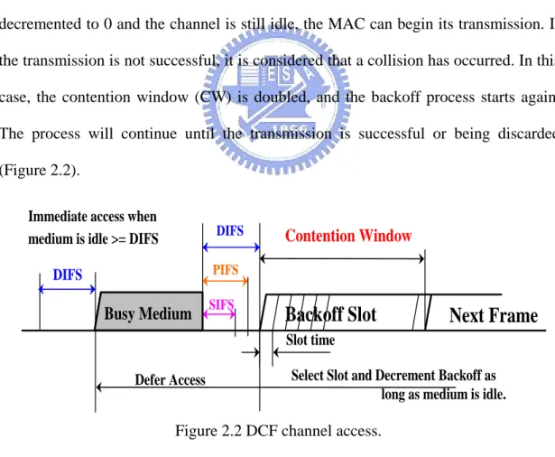
(12) 2.1.1 Distributed Coordination Function The DCF uses CSMA/CA, it is designed to provide asynchronous data transmission for best effort services. When a data frame arrives at a transmitting queue and the wireless channel is busy, the MAC will wait until the medium becomes idle. In order to reduce the probability of collisions, the DCF applies a collision avoidance mechanism (Backoff Time) to force the MAC to send the frame only after an extra time interval called DCF inter-frame space (DIFS). Every user may use a different backoff time because the random backoff selects a value from 0 to the contention windows (CW) value randomly. Therefore, the MAC will start the backoff process with a backoff time if the channel is idle. Once the timer of the backoff slot is decremented to 0 and the channel is still idle, the MAC can begin its transmission. If the transmission is not successful, it is considered that a collision has occurred. In this case, the contention window (CW) is doubled, and the backoff process starts again. The process will continue until the transmission is successful or being discarded (Figure 2.2). Immediate access when medium is idle >= DIFS. DIFS. Contention Window. PIFS. DIFS. Busy Medium. SIFS. Backoff Slot. Next Frame. Slot time Select Slot and Decrement Backoff as long as medium is idle.. Defer Access. Figure 2.2 DCF channel access.. We can find that DCF does not differentiate the data traffic because the DCF is contention based. All traffic classes have the same priority to access the wireless 4.
(13) medium. Thus, different delays and bandwidth requirements of applications can not be differentiated through the use of DCF. When the network is overloaded, the DCF has no feasible method to solve these issues.. 2.1.2 Point Coordination Function The PCF pertains to 802.11 optional medium access mechanism but is not directly tied to CSMA/CA and provides contention-free frame delivery to and from the access point. The legacy 802.11 uses the PCF to support QoS for time-bound services. The PCF provides mechanism for prioritized access to the wireless medium, and it is centrally coordinated by a station called the point coordinator (PC). This station is typically the access point. The PCF medium has higher priority access than the DCF. With the PCF, the Contention-free period (CFP) and the contention period (CP) take its turn periodically over time. The PCF is used to access the channel during the CFP, whereas the DCF is used during the CP. The beacon frame is a management frame that maintains the synchronization of the local timers in the stations and delivers protocol related parameters. When the CFP begins, the PC accesses the medium in the same manner as a DCF station. The PC polls a station asking for the volition to transmit a pending frame. Whenever the PC itself has a pending frame destined to this station, it uses a combined data and poll frame by piggy-backing the CF-Poll frame onto the data frame. Upon receiving the CF-Poll+DATA, the polled station acknowledges the successful data reception. After waiting a time interval which is known as the priority inter-frame space (PIFS), the PC attempts to access the medium and polls the next station or end the CFP if the PC receives no response from the polled station. Since DIFS > PIFS, it allows PCF stations to access the medium. 5.
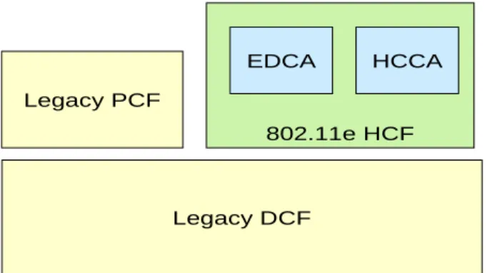
(14) before DCF stations as well as has higher probability of accessing the medium. However, there are still some problems in the PCF including the unpredictable beacon delay and unknown transmission durations of the polled station. In addition, the PCF supports time-bounded applications with some limitations. However, PCF is not supported by most wireless device vendors and has been shown the poor performance in the presence of DCF [7]. In order to solve the problem for differentiating between traffic type and sources with DCF and PCF, the IEEE is proposing the 802.11e to enhance both the DCF and PCF coordination functions to support QoS.. 2.2 IEEE 802.11e There are enhancements to the 802.11 MAC currently under development and these enhancements will be adopted in the 802.11e[8] extension of the 802.11 standard. The 802.11e has devised two proposed solutions for the future 802.11 MAC. This new standard introduces the hybrid coordination function (HCF), which defines two new medium access mechanisms to replace PCF and DCF. The HCF has two modes of operation: Enhanced Distributed Channel Access (EDCA) and the HCF Controlled Channel Access (HCCA). EDCA is a contention-based channel access function that operates concurrently with HCCA which is based on a polling mechanism and controlled by the hybrid coordinator (HC). (Figure 2.3).. 6.
(15) EDCA. HCCA. Legacy PCF 802.11e HCF. Legacy DCF. Figure 2.3 Draft of 802.11e architecture.. 2.2.1 Enhanced Distributed Channel Access (EDCA) The EDCA enhances the original DCF to provide prioritized QoS, such as DiffServ. The QoS support is realized with the introduction of Access Categories (ACs), which maps the classes defined in the 802.1D standard to the corresponding categories, as shown in Table 2.1.. 802.11e 802.1D User Priority Designation Access Category (AC) Designation 1 BK AC_BK Background 2. -. AC_BK. Background. 0. BE. AC_BE. Best Effort. 3. EE. AC_BE. Best Effort. 4. CL. AC_VI. Video. 5. VI. AC_VI. Video. 6. VO. AC_VO. Voice. 7. NC. AC_VO. Voice. Table 2.1 Mapping between 802.1D priorities and EDCA access categories.. 7.
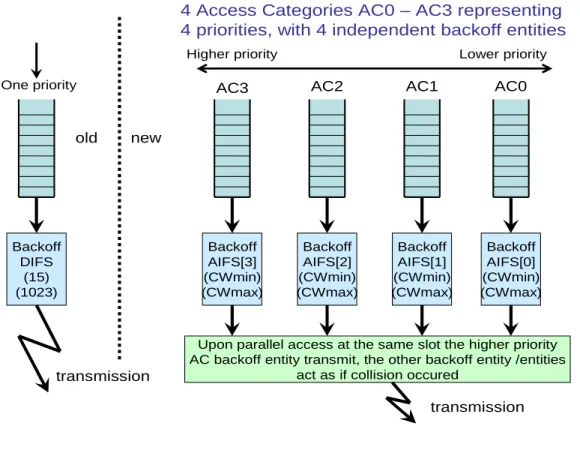
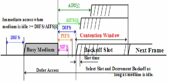
(16) In the EDCA, the priorities of channel access are accomplished by defining the AC at the client stations. In each station, there are four ACs, each of them has its own MAC queue and backoff counter so that packets are sorted according to their priority (Figure 2.4).. 4 Access Categories AC0 – AC3 representing 4 priorities, with 4 independent backoff entities Higher priority One priority. old. Lower priority. AC3. AC2. AC1. AC0. Backoff AIFS[3] (CWmin) (CWmax). Backoff AIFS[2] (CWmin) (CWmax). Backoff AIFS[1] (CWmin) (CWmax). Backoff AIFS[0] (CWmin) (CWmax). new. Backoff DIFS (15) (1023). transmission. Upon parallel access at the same slot the higher priority AC backoff entity transmit, the other backoff entity /entities act as if collision occured. transmission. Figure 2.4 Access Category (AC) architecture.. An AC begins to decrement its backoff counter once the medium has been idle for a period of time called the Arbitration Inter-Frame Space (AIFS). The AIFS is no smaller than DIFS, and is chosen for each AC independently. The ACs with higher priority will get a shorter AIFS than the ACs with lower priority. Each data unit will be delivered through each AC backoff instances to which it belongs respectively in a station (Figure 2.5). Since the low-priority AC has longer AIFS, the low priority data unit will have to wait until the high priority data units finish accessing the medium. Therefore, with the EDCA, we can classify the data unit by giving the data unit 8.
(17) different priorities and differentiate the different Quality of Services.. Figure 2.5 EDCA channel access.. 2.2.2 HCF Control Channel Access (HCCA) The operation of the HCCA is similar to the PCF. It inherits some rules of legacy PCF and it also introduces many extensions. The access point contains the hybrid coordination (HC) that keeps tracks of the HCCA client station and schedules the polling intervals. Unlike the PCF operation, the HCCA polling access can occur during the contention period and coexist with EDCA. The access point can start a contention-free HCCA period if the medium has been remaining idle for a PCF inter-frame space period, which is shorter than the minimum AIFS. In addition, the HCCA provides deterministic behavior and a high level of control and fidelity to multimedia applications that require parameterized QoS. However, the HCCA needs a more complex hardware implementation, and it contains many unsolved issues, such as how the HC should manage the polling of a large number of interactive streams without harming applications using EDCA scheme. 9.
(18) 2.3 Use Existing System or Software to Provide QoS At present there are a number of vendors of wireless LAN products and operating system providing the utilities for users to obtain the information of wireless network, which the users could join [9,10]. Here we have the Lucent wireless card which uses its own utility and detects multiple access points (Figure 2.6). With the tool we can obtain the information of wireless networks, such as observed networks, current access point information of using channel, SSID, signal strength, SNR and so on (Figure 2.7&2.8). Other wireless card utilities can also provide similar information to the user. According to the information, we can roughly know the basic information of these access points.. Figure 2.6 Lucent Utility with detection of 4 APs.. 10.
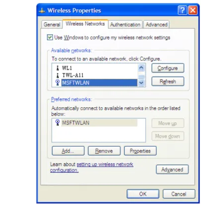
(19) Figure 2.7 Information of access point.. Figure 2.8 More detailed information of access point.. Some operating systems, for example the Windows XP, can also provide and tabulate the information of multiple access points which the wireless card can access. By using this list, we can select one access point and associate with it for wireless connection (Figure 2.9). 11.
(20) Figure 2.9 Windows XP wireless configuration.. We receive the information from multiple access points based on use this information we can determine which AP we will associate with. Generally, we simply select the access point with the strongest signal strength. However, the AP with the strongest signal sometimes cannot support the quality of service we need and unfortunately we may not be able to get enough information to judge whether the selected access point is highly loaded? If we require better QoS under such circumstance, we need to give up this access point and choose another one manually, then try whether it is also highly loaded. Otherwise, we have to endure the wicked wireless network and tolerate the poor performance. Therefore, the information only allow us to know the basic information of access points, but not the QoS. Although there are new techniques or firmwares providing the measurement of the loading of APs to users, it is still not sufficient for 12.
(21) users to clarify whether their requirements can be satisfied. We need other efficient mechanism to resolve this issue.. 2.4 Related Research Recently, there are quite a few research regarding the QoS and load-balancing. In [11,12] , it proposed the schemes to modify the MAC protocol in wireless LAN for supporting different service requirements using both centralized and distributed method. These schemes focused on the fairness properties of the wireless MAC in order to provide different class flows, and they are not appropriate for dynamic provisioning of the QoS. There are also researches about resource reservation and admission control scheme to provide QoS [13]. Although some of the ideas are useful, there are still some major problems. Since the resource reservation results in large overhead for supporting QoS requirements dynamically, thus the actual performance is not very good [14]. Besides, both these schemes are triggered by mobile nodes, and sometimes the mobile nodes should move around to find another better access point with better service. The mobile node users may experience the inconvenience to move around, and the access point can not trigger the load–balancing mechanism by itself. In order to solve these problems, we propose an efficient mechanism to support QoS dynamically and improve the load-balancing between access points in wireless network.. 13.
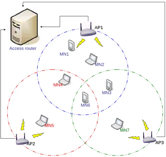
(22) Chapter 3 Proposed Channel Switching Mechanism for QoS. In order to provide per-user QoS and the access points load balancing across the overlapping region in a wireless LAN, we present a channel switching mechanism in this chapter. The whole mechanism is composed of two main modules: (1) dynamic QoS guarantee, (2) channel switching. We will introduce them in the following sections.. 3.1 System Overview Before introducing the system, we would like to describe a scenario of our system first. As illustrated in Figure3.1, there are seven mobile nodes and three access points (AP) with overlapped coverage regions. The AP1, AP2, and AP3 connect to the same access router within the same domain. The MN1, MN2, MN3, MN6 are associated with AP1; MN4 and MN5 are associated with AP2 and MN7 is associated with AP3. As shown in the figure, the MN4 is covered by both AP1 and AP2; the MN3 is covered by both AP1 and AP3; the MN6 is covered by all three APs. Assuming that AP1 has the lowest bandwidth available, and other two APs still have plenty of bandwidth. If new users want to associate with AP1 and use wireless LAN to download files or run real-time service, the mobile nodes associated with AP1 will find their transmission rates getting slower and slower. At this time, the AP1 can not guarantee any QoS such as throughput, and the congestion will worsen so that it affects the service quality of mobile nodes within the wireless network. However, if one or more mobile nodes de-associate with AP1 and re-associate with other two. 14.
(23) overlapping access points, the overall throughput of network can be improved. For example, the AP1, AP2 and AP3 are visible from MN6; therefore if MN6 could to move to AP2, the load on AP1 will be reduced. Also, AP1 and AP3 are visible from MN3, therefore if MN3 can be switched to AP3 the loads on AP1 will be decreased further.. AP1. Access router MN1 MN2. MN4 MN3 MN6. MN5 MN7 AP3. AP2. Figure 3.1 Multiple APs with overlapped coverage area.. In order to resolve this problem and support load-balancing between APs, we introduce our mechanism which consists of three main components: (1) a dynamic QoS guarantee mechanism, (2) an access point availability check function, and (3) a channel switching mechanism. In the QoS guarantee mechanism, we have a QoS. 15.
(24) manager which works both in access points and mobile nodes, and an QoS negotiator that works between an access point and mobile nodes. Regarding the access point availability check function, it ties to finding whether there is any available access point available for re-associating with the mobile node. In the channel switching mechanism, we have the load-balancing control algorithm to decide how many mobile nodes should change their association with the access point and which access point that mobile node can join in, and the re-association announcement to inform the mobile nodes and access point about the re-association information. Therefore, the overall system is constructed by a decentralized approach instead of a centralized one, and the mechanism can be triggered either by the mobile node or the access point. Beside, it does not need any extra hardware modification or maintenance effort in the current network structure. In the following sections, we will introduce all the components in our mechanism in more details.. 3.2 Dynamic QoS Guarantee Mechanism In order to guarantee the QoS dynamically, firstly we need the QoS manager which works in all access points and mobile nodes to monitor the traffic load. It allows us to know when we could send out the QoS request if necessary. Secondly, when we send out the QoS request, we need to trigger a procedure to negotiate the QoS between the access point and the mobile node, and then trigger the channel switching mechanism.. 3.2.1 QoS Manager The QoS Manager has three tasks: (1) monitoring the traffic loads and check whether it exceeds the threshold, (2) to send out the QoS requirement, (3) to exchange 16.
(25) the load information with other QoS Manger of access points. Since each mobile node has different service requirements ( i.e. throughput, loss rate, jitter) for their application through wireless LAN. In order to monitor the traffic loads and trigger the QoS negotiation procedure in time when necessary, the QoS manager runs in both the access point side and the mobile node side. The QoS requirements are predefined with certain levels (basic, advanced, premium...etc) for different types of traffic. On one hand, if the mobile node feels that the network quality is not good enough for its use, the QoS manager of the mobile node can trigger the QoS negotiation procedure by specifying the quality level it desires. On the other hand, the access point determines its affordable resource threshold. When the load of the access point exceeds the threshold, the QoS manager of the access point will also trigger the QoS negotiation procedure to ask some mobile nodes to re-associate with other access points whose loads are not so heavy. In other words, either an AP or a mobile node can trigger the QoS negotiation procedure. Each access point maintains a table that records all the access points which have overlapped covering regions initially. Besides, the QoS manager running on each access point also shares the load information to those access points that cover the overlapped regions via the wired connections. Therefore, the QoS manager on each access point has to send its own traffic load announcement periodically and receive the announcements from other access points which have overlapped regions. By using this method, the QoS manger of each access point can collect others’ traffic load information and update it periodically for the channel switching mechanism to refer to.. 17.
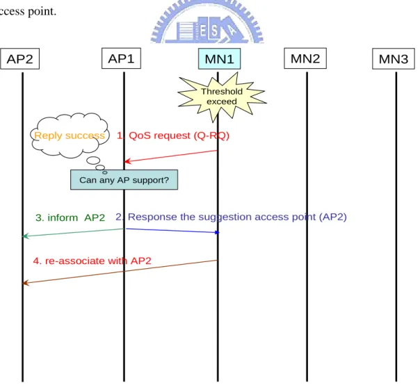
(26) 3.2.2 QoS Negotiator The QoS negotiator is proposed to communicate between the mobile node and its associated assess point. The negotiator can be triggered either by the mobile node or the access point. There are three cases in which the QoS negotiation will be triggered, as described follows:. Case 1: Figure 3.2 shows a simple scenario of the QoS negotiation procedure. In this case, the mobile node sends out a QoS request, and the neighboring access point is able to support its requirement. The current assess point will inform the mobile node to re-associate with this neighboring access point, and then inform the neighboring access point.. AP1. AP2. MN1. MN2. MN3. Threshold exceed. Reply success. 1. QoS request (Q-RQ). Can any AP support?. 3. inform AP2. 2. Response the suggestion access point (AP2). 4. re-associate with AP2. Figure 3.2 A mobile node triggers the QoS negotiator mechanism (Simple Case). 18.
(27) Step1: If the QoS manger of MN1 finds that the service requirement can not be fulfilled using the transmission, it will send a QoS request packet (Q-RQ) to the associated AP1. The QoS request packet contains the serivce type, the level of the service (TF_Level) required and a list of APs (MN_APList) which the mobile node can hear. The information will be used in the channel switching mechanism. Step2: When AP1 receives the Q-RQ packet, it will perform the access point availability check function. If the function returns a success message, which means there is a suitable access point being able support this QoS requirement (more details in Section3.3), then the access point will respond with an access point SSID (AP2) announced by channel switching mechanism and the MN1 will re-associate with AP2 upon receiving the SSID.. Case 2: Figure 3.3 illustrates another case about how the mobile node triggers the QoS negotiator mechanism when it is unable to re-associate with a new access point. The procedure is as follows: Step1: If the QoS manger of MN1 finds that the service requirement can not be met during the communication, it will send the Q-RQ packet to associate with AP1. The QoS request packet (Q-RQ) contains the information of the service and the AP list which can be used in the channel switching mechanism. Step2: When the AP1 receives the Q-RQ packet, it will start the AP availability check function. If the function returns a fail message, which means that no suitable access point can support this QoS requirement (more details in Section3.3), then the access point will broadcast a QoS AP List Request (Q-List-RQ) packet to the mobile nodes currently associating with the AP1 (say, MN1, MN2 and MN3). The Q-List-RQ packet here is proposed to ask every mode within the AP1’s covering region for the 19.
(28) MN_APList which the mobile node can hear. In this situation, the AP1 will reject any later QoS request until it finishes the channel switching mechanism, when the AP1 has triggered the QoS negotiation. Step3: After receiving a Q-List-RQ QoS packet, each mobile node (MN1, MN2 and MN3) will respond a QoS AP List Response packet (Q-List-RS) to the AP1. The Q-List-RS packet includes (1) the level of service required for the mobile node, (2) the service type, (3) the list of APs that the mobile node can hear. The later information is obtained using the inherent ability of the user’s wireless PC card to scan the local network. Beside, the MN_APList are sorted in descending order with the key Signal-Noise-Ratio (SNRs). After receiving all the Q-List-RS, the AP1 will use this information to enable the channel switching mechanism.. Figure 3.3 A mobile node triggers the QoS negotiator mechanism.. 20.
(29) Case 3: Figure 3.4 illustrates how the access point triggers the QoS negotiator mechanism by itself. There are only two steps which are same as that in Figure 3.3 with its Step 1 taken away.. Figure 3.4 An access point triggers the QoS negotiator mechanism.. Step1: The QoS manger of AP1 finds that the traffic load exceeds the threshold during the communication. At this time, the AP1 will reject the later QoS request until it finishes the channel switching mechanism after it triggered the QoS negotiation. The AP1 will broadcast the Q-List-RQ packet to the mobile nodes currently associated with it (MN1, MN2 and MN3). The Q-List-RQ packet here is proposed to ask every mobile node within the AP1’s covering region regarding the list of APs. 21.
(30) which the mobile node can reach. Step2: After receiving the Q-List-RQ packet, each mobile node (MN1, MN2 and MN3) responds with a Q-List-RS packet to the access point (AP1). The Q-List-RS packet contains (1) the level of service required for the mobile node, (2) the service type, (3) the MN_APList which the mobile node can hear. After receiving all Q-List-RS, the AP1 will use this information to enable the channel switching mechanism.. 3.2.3 Coordinate Dynamic QoS Guarantee Mechanism In the previous section, we introduced the main modules of dynamic QoS guarantee mechanism. In this section we will explain the details of the dynamic QoS guarantee mechanism. On one hand, the QoS manger of mobile nodes can send out a QoS request packet to tell the access point that its requirement is insufficient to support the requested service, and ask the access point to provide more resources by using the access point availability check function and the channel switching mechanism. On the other hand, the access points also run the QoS manger to monitor whether the traffic loads exceeding the threshold. In this way, the access points can also trigger the QoS negotiation mechanism without mobile nodes announcements on their own initiative. Firstly, when the mobile node notices that the resource is not satisfactory for its associating access point, it will send the Q-RQ to ask the access point to enable the AP availability check function, no matter the replied message is a success or a failure. If the replied message is a success, the original access point will tell the mobile node to re-associate with the new access point; otherwise, it will broadcast the Q-List-RQ packet to all associated mobile nodes to ask for the MN_APList from the mobile. 22.
(31) nodes. In order to minimize the side effect to the network, one important thing is that when the access point starts to trigger the QoS negotiation mechanism, any following QoS requests will be rejected until the channel switching procedure is done. Otherwise, if too many QoS requests are submitted at the same time, the access point will broadcast messages again and again which may lead to the network congestion. After receiving the Q-List-RQ packet, each mobile node will respond with a list of reachable APs which is sorted by SNR in a descendent order. When the access point obtains the response from each mobile nodes, the channel switching mechanism of the access point will start. Figure 3.5 shows the flowchart of dynamic QoS guarantee mechanism.. 23.
(32) Mobile Node. Access Point. QoS Manger. QoS Manger. No. No. Threshold exceed ?. Threshold exceed ?. Yes. QoS negotiation. Send QoS Request. Yes Blocked ?. Reject the QoS Request. No Yes Is access point availability check function return success? No QoS negotiator. Broadcast QoS Ap List Request. Receiving QoS List of APs. Channel Switching Mechanism. Figure 3.5 Dynamic QoS Guarantee Mechanism.. 24. Reply the new AP’s SSID to MN.
(33) 3.3 Access Point Availability Check Function We introduce two parameters in this mechanism. (1). AP_Info: the table records the SSID and the remaining bandwidth of the access point, as well as the load information exchanged by its neighboring APs.. (2). MN_APList : the list of APs which can be heard by a mobile node.. When the access point receives a Q-RQ packet, the packet carries the service requirement from the mobile node. According to this information, we check the service quality requirement table defined by the access point. The service quality requirement table defines various service type, and each different service type is classified into three levels (Basic, Advanced, Premium) which have their own threshold condition (Table 3.1). For example, the Q-RQ packet requests one kind of level for video service. The access point availability check function will check the original traffic status with mobile node. If the mobile node asks for the quality which is worse than what it already have (Advanced -> Premium), the access point will ignore this request. Otherwise, the access point will execute the function and try to find an available access point for the requesting mobile node. The ideal situation for our system is that some neighboring access points in the AP_Info can fulfill the QoS requirement for the asking mobile node without using the channel switching mechanism to ask other mobile nodes for re-association. Therefore, if the access point receives a Q-RQ packet from the mobile node, we will examine the access points listed in the Q-RQ packet one by one. And the access points in the list are sorted according to the remaining resources. If we do find a SSID that occurs in both the AP_Info and the MN_APList, we will further check whether the remaining. 25.
(34) resource of the entry found in the AP_Info satisfies the resource requirement of the requesting mobile node. Once the requirement is fulfilled, the access point availability check function mechanism will respond with a success message and inform the mobile node regarding the new entry's SSID to re-associate with. Besides, the access point availability check function will also inform the access point which owns the SSID that. a mobile node is going to associate with it. If, unfortunately, there is no. such entry that satisfies the resource requirements in both the AP_Info table and the access point list, then the access point availability check function will respond with a failure message and trigger the QoS negotiation mechanism. There are illustrations in Figure 3.2 and Figure 3.3.. Service Type. Video. Voice. Best effort. Default. Level. Throughput. Delay. Jitter. Premium. Video_TH_3. Video_D_3. Video_J_3. Advanced. Video_TH_2. Video_D_2. Video_J_2. Basic. Video_TH_1. Video_D_1. Video_J_1. Premium. Voice_TH_3. Voice_D_3. Voice_J_3. Advanced. Voice_TH_2. Voice_D_2. Voice_J_2. Basic. Voice_TH_1. Voice_D_1. Voice_J_1. Premium. BE_TH_3. BE_D_3. BE_J_3. Advanced. BE_TH_2. BE_D_2. BE_J_2. Basic. BE_TH_1. BE_D_1. BE_J_1. Basic. DF_TH_1. DF_D_1. DF_J_1. Table 3.1 Threshold of service type and level.. 26.
(35) 3.4 Channel Switching Mechanism When the access point triggers the QoS negotiation mechanism, it means that some mobile nodes should change their association with other neighboring access points if possible. Therefore, the channel switching mechanism needs the information about both the service requirement and these access points heard by each mobile node. The access point can obtain much useful information provided by the QoS manger. According to the information, the channel switching mechanism will select the best access point from a list of APs which is stored in the QoS AP list response, and ask the mobile node to re-associate with this new access point. The channel switching mechanism contains the load-balancing control algorithm and the re-association announcement. The operation and the relationship of them is that, if the access point receives a Q-List-RS packet, it will start the load-balancing control algorithm first to determine which mobile nodes should re-associate with which access point, according to the access point information contained in the MN_APList. Secondly, the re-association announcement is used to inform both the neighboring access point which can support the service requirement from these mobile nodes as well as the mobile node which need to do re-association. We will introduce more details about these mechanisms. 3.4.1 Load-Balancing Control Algorithm At the beginning, we introduce some parameters used in this algorithm. (1) AP_Info: a table that records the SSID and the remaining resource of the access point and its neighboring access points. (2) MN_Info: a table that records the resource requirement and the APs list heard by the mobile node. 27.
(36) (3) Re-associate_Info: a table that records the mobile node and its newly re-associated SSID. (4) RSoriginal_req: the resource requirement from initial QoS request packet and re-defined by the service quality requirement table, or defined by access point. (5) RSprovide: it indicates the available resource in the access point after redistributing the mobile nodes. (6) RSremain: the remaining resource of each neighboring access point, stored in the AP_Info. (7) RSrequire: the resource requirement re-defined by the service quality requirement table from each mobile node, recorded in MN_Info.. When the access point receives a Q-List-RS packet, it will run the load-balancing control algorithm. The Q-List-RS packet contains the information about: (1) the level of service required for the mobile node (RSrequire), (2) service type, (3) the list of APs which the mobile node can hear (MN_APList), this is stored in MN_Info table. Moreover, the access point has the load information of neighboring access points by using the QoS manger to exchange the announcement to each other, this contains SSID and RSremain,, which are stored in AP_Info. According to the above information stored in AP_Info and MN_Info, the load-balancing control algorithm can calculate the total resource that neighboring access points can provide, as well as how many and which mobile nodes have to re-associate.. [Scenario] To explain our algorithm we use a scenario for demonstration. There are four 28.
(37) access points in the network (AP1, AP2, AP3 and AP4), and six mobile nodes (MN1, MN2,…, and MN6) associated with AP1. Before we run the algorithm, we should define the RSoringin_req value initially. There are two methods to define the RSoringin_req: (1) If the mobile node has sent the Q-RQ and the AP availability check function replies a failure, the RSoringin_req is equal to the service’s level threshold in the service quality requirement table (defined in Section 3.3), (2) Otherwise, if the access point triggers the QoS negotiation by itself, the RSoringin_req is defined by the access point (Ex: 10% of its capacity). In this scenario, for example, the RSoringin_req is set to 900. Besides, we also sort the AP_Info table with the key RSremain in descendent order (Figure 3.6).. AP_Info SSID. RSremain. AP2. 500Kb. AP3 AP4. AP_Info SSID. RSremain. AP4. 800 Kb. 300 Kb. AP2. 500 Kb. 800 Kb. AP3. 300 Kb. sorted by RSremain descending. Figure 3.6 The AP_Info table is sorted with RSremain.. After that we start the algorithm and configure each mobile node’s RSrequire by looking up the service quality requirement table; To find whether there is any access point which can be re-associated with, we examine the RSrequire in the MN_Info and the RSremain in the AP_Info. Besides, we also check the record in MN_Info in order by the following condition: (1) Has this record of MN_Info been marked?( it means this record has been assigned a new SSID to re-associate with) , 29.
(38) (2) Can this SSID of the AP_Info be found in APs list of current mobile node from MN_Info? , (3) Is the RSremain equal or greater than RSrequire of current mobile node from MN_Info?. By using these three conditions, we can judge that is the current access point suitable for the current mobile node. (Figure 3.7). MN_Info. AP_Info SSID. MN. RSremain. Step 1. 800. AP4. 500. AP3. 300. RSoriginal_req =900 RSprovide. …... AP2. Step 2 Step 3. RSrequire APlist[0] APlist[1] APlist[2] APlist[3] Marked 900. AP1. MN2. 500. AP1. MN3. 300. AP1. MN4. 300. AP1. MN5. 400. AP1. AP2. MN6. 500. AP1. AP2. MN1. No. AP4. No AP2. AP4. No No No. AP3. AP4. No. =0 AP4 can not support the requirement of MN1. Re-associate_Info MN MN3. SSID. AP4 can not be heard by MN1 AP4 can be associated with MN3, and it recorded to the Re-associate_Info. AP4. : match. : not match. Figure 3.7 Comparison of the AP_Info with MN_Info.. If all answers are “YES”, it means that the current access point can provide the bandwidth and can be associated with current mobile node, so we set “YES” to the marked value to express that it has already been assigned a new SSID. We also record the current mobile node and its new SSID into the Re-associate_Info, and we will calculate the following equations:. 30.
(39) (1) RS provide = RS provide + RS require _ j , (2) RS remain _ i = RS remain _ i − RS require _ j .. Otherwise, it means that the current access point does not meet the QoS requirement of the current mobile node or the current mobile node has already assigned a new SSID to re-associate with. Therefore, we need to check the next record in MN_Info and repeat the procedure, until the RSprovide is increasing to enlarge the RSoringin_req or there are no more matched record in both the AP_Info and the MN_Info. The process is shown in Figure 3.8 (a) – (c).. MN_Info. AP_Info SSID. MN. RSremain. 900. AP1. MN2. 500. AP1. MN3. 300. AP1. MN4. 300. AP1. MN5. 400. AP1. AP2. MN6. 500. AP1. AP2. AP4. 800. MN1. AP2. 500 300. AP3. RSoriginal_req =900 RSprovide. RSrequire APlist[0] APlist[1] APlist[2] APlist[3] Marked No. AP4. No AP2. AP4. No No No. AP3. AP4. =0. Re-associate_Info MN. SSID. MN3. AP4. MN6. AP4. AP4 can be associated with MN3 and MN6, and it is recorded in the Re-associate_Info. : match. : not match. Figure 3.8(a) The first round of the procedure.. 31. No.
(40) MN_Info. AP_Info SSID. MN. RSremain. RSrequire APlist[0] APlist[1] APlist[2] APlist[3] Marked. AP4. 0. MN1. 900. AP1. AP2. 500. MN2. 500. AP1. AP3. 300. MN3. 300. AP1. MN4. 300. AP1. MN5. 400. AP1. AP2. MN6. 500. AP1. AP2. RSoriginal_req =900 RSprovide. No. AP4. No AP2. AP4. Yes No No. AP3. AP4. Yes. =800. Re-associate_Info MN. SSID. MN3. AP4. MN6. AP4. MN5. AP2. AP2 can be associated with MN5, and it is recorded in the Re-associate_Info. : match. : not match. Figure 3.8(b) The second round of the procedure.. MN_Info. AP_Info SSID. MN. RSremain. RSrequire APlist[0] APlist[1] APlist[2] APlist[3] Marked. AP4. 0. MN1. 900. AP1. AP2. 100. MN2. 500. AP1. AP3. 300. MN3. 300. AP1. MN4. 300. AP1. MN5. 400. AP1. AP2. MN6. 500. AP1. AP2. RSoriginal_req =900 RSprovide. No. AP4. No AP2. AP4. Yes No Yes. AP3. AP4. Yes. = 1200. Re-associate_Info MN. SSID. MN3. AP4. MN6. AP4. MN5. AP2. RS provide = 1200 ≥ RS original _ req = 900 : match. : not match. Figure 3.8(c) The final result of all parameters.. 32.
(41) The more detailed algorithm is shown in Figure 3.9. In this algorithm, we check not only the record in the AP_Info and MN_Info, but also RSprovide during the procedure. If RSprovide is equal to or greater than RSoriginal_req, we will exit the procedure because it means that we only need to ask these mobile nodes to re-associate with, then we can support the original QoS requirement. We do not check the other access points or mobile nodes so that we can reduce unnecessary overhead and determine the list of re-associating mobile nodes as quick as possible.. Figure 3.9 The Load-balancing Control Algorithm.. At last, the records in the Re-associate_Info can be used to provide the channel switching mechanism to be announced to the mobile nodes. However, if no mobile nodes can hear other access points except the currently associating AP or no access 33.
(42) point can support the mobile nodes’ requirement, there will be no record stored in Re-associate_Info, and it means that the request QoS service can not be supported.. 3.4.2 Re-associated Announcement When we finish the load-balancing control algorithm, the re-association announcement will be used. The purpose of the re-association announcement is to inform the mobile node to re-associate with another access point, and to inform the access point that a mobile node is going to associate with it. After finishing the load-balancing control algorithm, there may be some record in the Re-associate_Info (defined in Section 3.4.1). If there is at least one record, then the access point will send announcements with the new SSID to the mobile node Re-associate_ Info table one by one to inform the mobile nodes which access point they should re-associate with. Then the access point will also inform these new access points regarding those mobile nodes to be associating with them. As long as RSprovide becomes no less than a half RS orginal_req. orginal_req,. even if the RSprovide is smaller than the RS. after finishing the algorithm, we will still ask the mobile node in the. Re-assocaite_Info table to perform re-association. Although this action may not fulfill the requested requirement, it can reduce some traffic loads. When a mobile node receives this announcement it will re-associate with the new access point. Therefore, the traffic load will be reduced after this procedure. However, if the Re-associate_Info table is empty, it means that there is no mobile node could re-associate with or no access point could support this kind of QoS requirement, and the access point will respond a request failare use message to the requesting mobile node. Figure 3.10 shows the procedure of re-association announcement, according to the Case 2 in Section 3.2.2 (Figure 3.3). After the second channel switching. 34.
(43) mechanism, the AP1 asks the MN2 and MN3 to re-associate with the AP2 and AP3 respectively (Step 4), as well as inform the AP2 and AP3 that there will a new mobile node to be associating with them (Step 5). Later, when the MN2 and MN3 join AP2 and AP3, the channel switching is completed and the traffic load of the AP1 will be reduced.. AP2. AP1. AP3. MN1. MN2. MN3. Threshold exceed. Reply fail. 1. QoS request (Q-RQ). Can any AP support?. 2. Broadcast QoS AP list request (Q-List-RQ). 3. QoS AP list response (Q-List-RS). Enable channel switching. 5. Inform the AP2 and AP3. 4. Send the announcement to MN2 and MN3. 6. re-association 6. re-association. Figure 3.10 The re-association announcements procedure. 3.5 Cooperation of Proposed Mechanisms When our system works in the wireless network, the dynamic QoS guarantee mechanism cooperates with the AP availability check function and the channel switching mechanism. The dynamic QoS guarantee mechanism works both in the mobile nodes and the access points. By using this mechanism, it not only monitors the 35.
(44) traffic load in each element in wireless network, but also triggers the mechanism to QoS guarantee on time. In addition, it also collects the information of service requirement, the remaining resource of the neighboring access points and so on, which will be used in either the channel switching mechanism or the AP availability check function. Besides, in order to guarantee the QoS dynamically, the mobile nodes will put forward their service requirement as necessary, and the access point will accept and deal with these requirement requests one by one. The AP availability check function only works in the access point. It is designed to find out whether there is neighboring access point suitable for the mobile nodes without asking other mobile nodes to do re-association. When we receive the QoS requirement of the dynamic QoS guarantee mechanism from the mobile node, we will check the availability of neighboring access points using this function. If the answer is “success”, then we do not have to ask other mobile node for re-association. Otherwise, we will use other mechanism to solve this problem. If the access point needs to ask the associated mobile nodes for re-association, we will use the channel switching mechanism, which only works in access point. By using the load-balancing algorithm of the channel switching mechanism, it can determine which mobile node should re-associate with which access point. After we obtain the list of the re-association information, the re-association announcement will inform both neighboring access points and mobile nodes. After these procedures, the QoS service can be achieved and traffic load balance in access point can be improved.. 36.
(45) Chapter 4 Performance Evaluation. In this chapter, we evaluate the performance of the channel switching mechanism for the QoS on wireless network. We use the network simulation “ns-2 version 2.27”[15] to evalute the performance of our system. In Section 4.1, we first show an overview of the scenario. In Section 4.2 and 4.3, the experiment results of the network are presented.. 4.1 Experimental Scenario Figure 4.1 shows our scenario for performance evaluation in the system.. 100Mbps 1ms. AP2. AP1. MN1 MN7 MN3. MN2. MN5 MN6. MN4. 100Mbps 1ms. Access router 100Mbps 1ms AP3. 100Mbps 1ms. Figure 4.1 Simulation scenario.. 37. AP4.
(46) There are four access points and seven mobile nodes in the network. On one hand, each access point connects to the access router with a 100Mbps/1ms wired link, and each has some overlapped coverage in the network. On the other hand, the mobile nodes use IEEE 802.11b standard supporting a data rate of 11Mbps to communicate with the access points. At the beginning of our simulation, there are six mobile nodes (MN1, MN2,…,MN6) associating with AP1 and one mobile node (MN7) associating with AP2, and the AP3 and AP4 have no mobile nodes associating with them. Later we will run some applications with TCP or UDP traffic to demonstrate the performance in mobile nodes and the overall network utilization.. 4.2 Performance Comparison Based on the scenario in Section 4.1, we use the FTP application with TCP traffic for mobile nodes to communicate with access points and the total simulation time is 300 seconds. In this section, we will compare the performance between the QoS network and the non-QoS network.. [Throughput] Figure 4.2 illustrates the average throughput distribution under different numbers of mobile users. The result shows when more and more traffic pass through the AP1, the average throughput of MN1 will be decreasing. Therefore, the average throughput of the non-QoS network is 2230Kbit/sec with one mobile node, and if a new mobile node joins to the network, the throughput will be reduced to 1122Kbit/sec. When there are total six mobile nodes, the overall throughput of non-QoS network will be reduced to 371.8Kbits/sec. In this case, if the MN1 asks to use the channel switching mechanism to acquire the QoS, the throughput distribution will become. 38.
(47) more stable even if the total number of mobile nodes is increasing. Since we can trigger other mobile nodes (MN2, MN3, MN4, MN5, MN6) to re-associate with the neighboring access points which can provide better QoS service, unless that MN1 QoS-enable cannot reach other access points. In addition, the average throughput of the QoS network is about 2150 Kbits/sec and does not show any poor performance. It means that the network will benefit from our mechanism.. The throughput of MN1. Throughput (Kbits/sec). 2500 2000 non-QoS 1500. QoS. 1000 500 0 1. 2. 3 4 Number of Mobile Nodes. 5. 6. Figure 4.2 The throughput of MN1.. [Utilization] We can compare the users’ distribution between the cases with our mechanism to the original wireless network without it (Figure 4.3). In the non-QoS network, the AP1 has six mobile nodes with the heavy traffic load, whereas the other access points (AP2, AP3, AP4) have very light traffic load. All the mobile nodes are clustered in the AP1’s covering region, and the network cannot support the load balancing. However, for the QoS-enabled network, according to the initial location of the mobile nodes, 39.
(48) mobile nodes will be asked to re-associate with other access point if possible, and the access points’ traffic load can be balanced by using our mechanism.. Utilization 7. number of users. 6 5 4. non-QoS. 3. QoS. 2 1 0 AP1. AP2. AP3. AP4. Access Point. Figure 4.3 Utilization of each access point.. 4.3 The Performance for Various Service Requirements In the previous section, we can observe that the performance of our mechanism is better than the original wireless network. Now, we will focus on the performance of different service requirements to examine whether our mechanism can improve the QoS on wireless network. We will use two kinds of situation based on the scenario in Section 4.1 in order to compare the non-QoS network and the QoS-enable network for each different service requirements of mobile nodes.. [Case 1] : The basic requirement is satisfied We assume that initially there is a media server sending the video stream to the MN1 with 300 Kbps data rate in 1000-Byte UDP packets. Also, another mobile node joins the network and transmits the video data. Figure 4.4 shows that during the 40.
(49) beginning 0 ~ 20 seconds, five mobile nodes transmit application data. At the 20th seconds, the MN6 joins the network, and asks for the 500Kbps sending rate with the UDP packet size 1000 Bytes. The overall throughput of all mobile nodes is then decreased when there are more and more traffic entering this wireless network. The total simulation time in this case is 300 seconds. When the QoS manger of MN1 detects that the throughput is less than 280 Kbps which is not sufficient, the MN1 will send the Q-RQ packet to the access point to request basic video quality, and then the channel switching mechanism will be enabled. Therefore, the MN1 send the basic video request to the access point. Since MN1 cannot hear any other access point except the AP1, our mechanism cannot perform re-association and thus need to ask some other mobile nodes to re-associate with its neighboring access points. After the channel switching, the traffic load will be reduced after some mobile nodes has been re-associating with the other access point, and the throughput of MN1 in the QoS-enable network will become stable and reach 300Kbit/sec again. However, the throughput of the mobile node in the non-QoS network will become unstable and down to 227 Kbit/sec. In addition, the delay performance of the MN1 video traffic will be also reduced, as shown in Figure 4.5. If we use the channel switching mechanism, it will be reduced to 20ms comparing to the 115 ms delay in a non-QoS network. After re-associating with the new access point, the utilization of each access points is shown in Figure 4.6. The throughput and delay between the QoS and non-QoS network shows that our mechanism can improve the network performance effectively.. 41.
(50) MN1 Throughput 400. throughput Kbps/sec. 350 300 250 non-QoS MN1. 200. QoS MN1. 150 100 50 0 0. 50. 100. 150. 200. 250. 300. time. Figure 4.4 The throughput of MN1 with video traffic.. Delay of MN1, vedio traffic 0.14 0.12. Delay (sec). 0.1 0.08 non-QoS. 0.06. QoS. 0.04 0.02 0 -0.02 0. 50. 100. 150. 200. 250. 300. 350. Time (sec). Figure 4.5 The delay of MN1 with videos traffic.. 42.
(51) Utilization 7. number of users. 6 5 4. non-QoS. 3. QoS. 2 1 0 AP1. AP2. AP3. AP4. access point. Figure 4.6 Utilization of access points. (MN1 request Good Level Video service). [Case 2] : Higher level requirement is satisfied Figure 4.4, the MN1 only requests the throughput to reach 300Kbps which is same as the original requirement. If the MN1 wants a better video quality, it will need to send the Q-RQ packet for higher data rate. For example, it wants the data rate speeded up from the Advanced level (300Kbps) to the Premium level (600Kbps). In order to get the best video quality, we should ask more mobile nodes to re-associate with neighboring access points as more as possible to release more resource. When the throughput is decreasing or the mobile nodes want the access point to provide the QoS, the mechanism will be enabled. As shown in Figure 4.7, by using the proposed mechanism, the MN1 requests the Premium level of video, the throughput of the QoS-enable MN1 is growing very fast it reaches to 600Kbps at 100 seconds. On the other hand, the throughput of non-QoS MN1 is growing slowly and always below the requirement (600Kbps), because there is no enough resource which 43.
(52) can be provided to the MN1. Throughput of MN1 700. throughput Kbit/sec. 600 500 400. non-QoS. 300. QoS. 200 100 0 0. 50. 100. 150. 200. 250. 300. time (sec). Figure 4.7 Throughput of MN1 with Best Level of Video.. Delay for Best Video Quality 0.14 0.12. delay (sec). 0.1 0.08. non-QoS. 0.06. QoS. 0.04 0.02 0 0. 50. 100. 150. 200. 250. 300. time (sec). Figure 4.8 Delay of MN1 with Best Level of Video.. 44.
(53) Figure 4.8 shows the delay of MN1 with the Premium level of Video. We will ask four mobile nodes to re-associate with neighboring access points in order to provide the MN1’s quality requirement. After the channel switching mechanism, the delay will be reduced to less than 20 ms, because there are still two mobile nodes associating with the AP1 and sending the application data (Figure 4.8). Later, this mobile node will stop its transmission at 145 seconds, and the delay will be reduced to 0 second. After re-associating with the new access point, the utilization of each access points is shown in Figure 4.9.. Utilization 7. number of users. 6 5 4. non-QoS. 3. QoS. 2 1 0 AP1. AP2. AP3. AP4. access point. Figure 4.9 Utilization of access points. (MN1 request Best Level Video service). [Case 3] : Partially satisfied quality requirement In this case, we consider one situation that if the channel switching mechanism can provide at least half of the requirement rather than the whole requirement. Unlike previous case 2, we add more traffic loads to each mobile node, and there are only two mobile nodes re-associating with AP3 and A4 after the channel switching 45.
(54) mechanism. Figure 4.10 illustrates the throughput in this situation. When the traffic loads become heavier in each mobile node, we can also enhance the throughput of the MN1 by using our mechanism. The MN1 request the Premium level of video service, but only AP3 and AP4 can provide the quality requirement to MN4 and MN5, respectively. After the switching mechanism, although the resource provided to the AP1 cannot fully satisfy the MN1’s requirement, over half of the requirement is still satisfied. As shown in Figure 4.10, the throughput of MN1 is still increased significantly whereas the throughput of the non-QoS network is very poor. After re-associating with the new access point, the utilization of each access points is shown in Figure 4.11.. Throughput of MN1 700. throughput Kbit/sec. 600 500 400. non-QoS. 300. QoS. 200 100 0 0. 50. 100. 150. 200. 250. 300. time (sec). Figure 4.10 Throughput of MN1 for partially satisfied quality.. Therefore, we prove some advantage of the channel switching mechanism after simulating these three cases, there are: 46.
(55) (1) It can recover the quality from poor to normal quickly. (2) It can reduce the transmission delay and efficiently improve the average throughput of mobile node. (3) The mobile node does not need to move away to find out the other available access point or exam the access point one by one manually, if the mobile nodes is already in the overlapped region. (4) It can provide the dynamic QoS requirement for each mobile node. (5) It can achieve the load-balancing among neighboring access points and improve the overall utilization of the network.. Utilization 7. number of users. 6 5 4. non-QoS. 3. QoS. 2 1 0 AP1. AP2. AP3. AP4. access point. Figure 4.11 Utilization of access points for partially satisfied quality.. 4.4 The Overhead of Our Mechanism In order to provide the QoS with our mechanism, any benefit derived from the mechanism comes with certain cost to the user and the network. The wireless LANs have to be overlapping coverage among access points for our mechanism to work. 47.
(56) Therefore, the network administrator should effectively plan the location of the access points to provide the overlapping coverage beforehand. Fortunately, there are many wireless network established recently and most of them have overlapping coverage. By using this property, we can perform our mechanism under such network topology. Another overhead of our mechanism is to aggregate the load information from neighboring access points, and update this information periodically. In order to reduce the load of network, in our system, the load information is exchanged every few tens seconds. As a result, the load information does not impose heavy overhead on the mechanism in the communication to update the resource information. Later, for the mobile node, in order to de-associate from one access point and re-associate with a new one, some overhead regarding scanning RF channels and switching to the new channel. If the network is using the mobile IP, the overhead will increase because the mobile nodes need to register and authenticate with HA and FA. Therefore, when the mobile node is asked to re-associate with other AP, the connection may be broken for a short interval before finishing the channel switching procedure, if the access corresponding points are in different domain, and authentication is required.. 48.
(57) Chapter 5 Conclusions and Future Work. In this thesis, we proposed an efficient channel switching mechanism to improve the QoS in the wireless LAN. In general, when the mobile users want to use the wireless network, they usually associate with the highest signal strength access point from the heard list. But according to the users' behavior and some geographical reason, most people in the same area will connect to the same access point, therefore, the traffic load will become heavy. If the mobile users need the better service quality, there are two possible methods: (1) if the mobile node can hear other access point, then it can try to connect to them and check which access point can support its requirement, (2) if the mobile node cannot hear other access point, it may change its location and to try to find out other access point. Because of the above reasons, the mobile users may feel inconvenient for requesting better transmission quality. In our mechanism, firstly, we can change the mobile users’ association automatically and select the access point which can fulfill its requirement. Secondly, if there is no suitable access point for the requesting mobile node, we can ask other mobile node to re-associate with other access points in the overlapped region. In this way, the transmission quality can be improved without unnecessary movements, which the utilization and the performance of access points and overall network will also be improved. The simulation result shows that the mechanism can enhance the performance of the network and provide the QoS as quickly as it can. As part of the future work, we can implement it to the access point or base station. Also we can modify the channel switching algorithm by adding some priority 49.
(58) policy to decide which mobile nodes should perform re-association. For example, we can rank the mobile nodes based on re-associating times in order to avoid the overhead of frequent changing of association. We can also add the billing mechanism into our system. According to each user’s service change, the system will give mobile nodes different priorities for asking different levels of service requirement. By using our mechanism, the network administrator can decide how to re-distribute the association of mobile nodes by its own policy in order to enhance the performance on the wireless network.. 50.
(59) References [1] IEEE 802.11b/d3.0 Wireless LAN Medium Access Control (MAC) and Physical Layer (PHY) Specification, August, 1999. [2] D. Qiao, and S. Choi, “Goodput enhancement of IEEE 802.11a wireless LAN via link adaptation”. In Proc. IEEE ICC’2001, Helsinki, Finland, June 2001. [3] S. Mangold, J. Habetha, S. Choi, C. Ngo, “Co-existence and Interworking of IEEE 802.11a and ETSI BRAN HiperLAN/2 in MultiHop Scenarios”. In Proc. IEEE Workshop on Wireless Local Area Networks, Boston, USA, Sept. 2001. [4] S. Mangold, S. Choi, and N. Esseling, “An Error Model for Radio Transmissions. of. Wireless. LANs. at. 5GHz”.. In. Proc.. Aachen. Symposium’2001, Aachen, Germany, pp. 209-214, Sept. 2001. [5] B. Walke, Mobile Radio Networks, Chichester, Sussex, U.K.: Wiley & Sons. Ltd., 2nd Ed., 2001 [6] Pejman Roshan and Jonathan Leary, 802.11 Wireless LAN Fundamentals, Csico Press, Dec. 2003. [7] M. A. Visser and M. E. Zarki. “Voice and Data Transmission over an 802.11 Wireless Network”. In Proc. PIMRC’95, pages 648-652, Sep 1995. [8] IEEE, "Part 11, Wireless LAN Medium Access Control (MAC) and Physical Layer(PHY) Specifications: Medium, Access control (MAC) Enhancements for Quality of Service (QoS)", ANSI/IEEE Std 802.11e, Draft 5.0, July 2003. [9] Planex Communication Inc. Firmware Update for PLANEX PC Cards v1.0.0713, Nov 2004.. 51.
(60) [10] Cisco System Inc. Data Sheet for Cisco Aironet 350 Series Access Points, June 2001. [11] M. Barry, A. T. Campbell, and A. Veres, “Distributed Control Algorithm for Service Differentiation in Wireless Packet Networks”. In Proc. IEEE. Infocom’2001, April 2001. [12] S. Lu, V. Bhargavan, and R. Srikant., “Fair Scheduling in Wireless Packet Network”, In Proc. AVM Sigcomm’1997, pages 63-74, August 1997. [13] Anand Balachandran, Paramvir Bahl, and Geoffrey M. Voelker., “Hot-spot Congestion Relief in Public-area Wireless Networks”. In Proc. IEEE. WMCSA’2002, 2002. [14] Huan Chen, Sunil Kumar and C.-C. Jay Kuo, “Dynamic Call Admission Contaol scheme for QoS Priority Handoff in Multimedia Cellular Systems”. In Proc. IEEE 2002, 2002. [15] The Network Simulator – n2-2, http://www.isi.edu/nsnam/ns/. [16] Jihwang Yeo, Moustafa Youssef and Ashok Agrawala, “A Framework for Wireless LAN Monitoring and Its Applications”. In Proc. ACM MobiCom. 2004, Philadelphia, PA, October, 2004. [17] M. Shin, A.Mishra. and W. Arbaugh., “Improving the Latency of 802.11 Hand-offs using Neighbor Graphs”. In Proc. INFOCOM 2004, Hong Kong, China, March 2004. [18] Pai-Hsiang Hsiao, Adon Hwang, H. T. Kung, and Dario Vlah, “Load-Balancing Routing for Wireless Access Network”. In Proc. IEEE. INFOCOM 2001, 2001. [19] A. Balachandran, GM Voelker, P. Bahl, and PV Rangan., “Characterizing User Behavior and Network Performance in a Public Wireless LAN “. In. Proc. ACM SIGEMTRICS'02, June 2002. 52.
(61) [20] Samarth H. Shah, Kai Chen and Klara Nahrstedt, “Dynamic Bandwidth Management in Single-Hop Ad Hoc Wireless Neworks”. In Proc. ACM. Mobile Networks and Applications February 2005, Feb 2005. [21] S. H. Shah, and K. Nahrstedt. “Predictive Location-based QoS Routing in Mobile Ad hoc Networks”. In Proc. IEEE ICC’02, 2002.. 53.
(62)
數據

+7


相關文件
Quality kindergarten education should be aligned with primary and secondary education in laying a firm foundation for the sustainable learning and growth of
中華民國 107 年 05 初版..
Fig.2.14
[r]
//Structural description of design example //See block diagram
mass/ strength 6-12 months 2-5 years Body fat redistribution 3-6 months 2-5 years Cessation of menses 2-6 months n/a. Clitoral enlargement 3-6 months 1-2 years Vaginal atrophy
除了新聞報導,可以查看網路 評價(如 Google
SaaS 軟體即服務 ( Software as a Service) 建立在 PaaS 、 IaaS
