以掺釹晶體產生不同波長之高能量脈衝雷射及其波長轉換
210
0
0
全文
(2) 以掺釹晶體產生不同波長之高能量脈衝雷射及其波長轉換 Generation of Various High-pulse-energy Lasers with Nd-doped Crystals and Wavelength Conversions. 研 究 生:黃依萍. Student:Yi-Ping Huang. 指導教授:陳永富. Advisor:Yung-Fu Chen. 國 立 交 通 大 學 電 子 物 理 系 博 士 論 文. A Dissertation Submitted to Department of Electrophysics College of Science National Chiao Tung University in partial Fulfillment of the Requirements for the Degree of Doctor of Philosophy in Electrophysics June 2010 Hsinchu, Taiwan, Republic of China. 中華民國九十九年六月.
(3) 以掺釹晶體產生不同波長之高能量脈衝雷射及其波長轉換. 學生:黃依萍. 指導教授:陳永富. 國立交通大學電子物理學系博士班. 摘. 要. 全固態雷射和非線性光學波長轉換技術的研究不僅具有重要的學術意義,更具有重要 的應用價值。隨著高功率的雷射二極體的發展,高能量的固態雷射已成為目前的重點研究 之一。各類雷射增益介質具有不同多個斯塔克分裂能級的譜線,透過實現雷射增益介質本 身具有的各級譜線之波長,再結合非線性光學波長轉換技術可拓寬雷射的波長範圍與應用 領域。本文是以摻釹的雷射晶體作為研究,實現低增益譜線的準三階雷射波段和人眼安全 雷射波段。除了使用傳統的晶體式飽和吸收體作為被動式 Q 開關元件,我們針對不同波段 設計合適的半導體材料製作成量子井飽和吸收體,以產生高效率和高能量的脈衝雷射。半 導體材料除了作為雷射腔內的飽和吸收體,我們發展半導體週期性材料作為抑制強增益譜 線的一種新穎元件,此元件對腔內的損耗很低,對於實現高效率的低增益譜線之雷射相當 有價值。摻釹的雷射晶體在最強增益的波段 1.0 μm 已經有相當成熟和穩定的脈衝雷射研 究,對於各類的波長轉換技術是重要的關鍵之一。我們利用腔內的光學參數振盪器,產生 在 1.5 μm 附近的人眼安全波段雷射。以理論分析腔內的光學參數振盪器之優化,並以實 驗佐證,發展高效率、高能量的人眼安全波段雷射及雙波長雷射。透過雷射共振腔體的設 計,利用些微的熱透鏡效應去發展不穩定的雷射腔體,有效地改善雷射光束品質。. i.
(4) Generation of Various High-pulse-energy Lasers with Nd-doped Crystals and Wavelength Conversions. Student:Yi-Ping Huang. Advisor: Yung-Fu Chen. Department of Electrophysics National Chiao Tung University. ABSTRACT. As the development of laser diodes, they are helpful for solid-state lasers. High-pulse-energy solid-state lasers have been the main researches. There are many laser transition lines in each laser medium.. Based on the generation of various fundamental laser. wavelengths and nonlinear wavelength conversions, solid-state lasers can be applied in more fields.. In the thesis, Nd-doped crystals are chosen to be the laser media to realize the low-gain. quasi-three-level lasers and eye-safe lasers.. A good quasi-three-level laser in Q-switched. regime is potential and helpful for developing pulsed blue laser.. Besides the conventional bulk. saturable absorbers, we develop the suitable semiconductor materials for various laser transition lines to make a QWs saturable absorber.. Efficient, high-pulse-energy Q-switched lasers are. generated. In addition, semiconductor materials are not only used to be the absorber for passively Q-switched laser, but also to be the novel intracavity selective absorbers used for suppressing the higher gain lines. On the other hand, Nd3+-doped pulsed lasers at 1.0 μm have been maturely developed for many years and possess superior performances. We utilize the Nd3+-doped pulsed lasers at 1.0 μm as the pump lasers to generate eye-safe intracavity OPOs. Based on the numerical analysis and cavity design, we are devoted to generate highly efficient high-energy eye-safe lasers. ii.
(5) 誌謝 五年的交大研究所生活過得非常充實,在良好的研究環境讓我學習到很多。 很幸運地可以到陳永富 教授的實驗室做研究,以及結識很多朋友。感謝陳老師的 指導,無論是研究上的教導和討論,亦或生活上的經驗分享和指正,都讓我獲益 良多。也很感謝陳老師的信任,放心的讓我使用單價非常昂貴的 laser diode stack, 讓我在實驗上獲得許多別人少有的經驗。這學年當任霹靂博助教,從陳老師的上 課更加體驗到物理有趣的連貫,從與學生的討論練習表達。第二位要感謝的是黃 凱風 教授。感謝黃老師分享實驗上的想法及提供許多寶貴的材料,並且給予我許 多的幫助及多次的推薦。兩位良師在學術上的熱忱是我學習的楷模。 剛踏入實驗室的時候,覺得實驗室的學長姐都很熱心、親切與活潑;感謝美 玲、玲意(01)、亭樺(DEER)學姐們,和冠暐(老大)、國欽、聰憲、偉立(立趴)、仕 璋(小黃)、哲彥(ppman)學長們營造出非常和樂的研究環境。每天都很早到實驗室 的立趴傳授我一些基本雷射架設和最佳化的技巧;此外,非常感謝立趴用那台小 VW 幫我搬了無數次的家,以及生活上許多的幫助。博一期間與哲彥學長學習黃光 雷射,磨練了許多實驗的基本功。ppman 對研究的認真和努力,非常令我敬佩。 小黃的實驗分享與討論,讓我獲得許多經驗及更瞭解一些半導體的區塊。最感謝 的人之一,是我一開始最敬畏的蘇老大,直到後來親自被老大教導才健談了起來。 跟細心、想法獨到、光學很強的老大一起做實驗,常會發現有趣的東西及注意到 很多的小環節。感謝蘇老師 不厭其煩的指導、協助及傳授我如何做個好的實驗紀 錄,都使我成長很多。Deer 學姐的表達能力及做投影片的功力、勇於嘗試的態度 是我學習的目標。很感謝 Deer 對我的關心照顧與鼓勵,在異鄉可以遇到談心的朋 友非常開心。雖然與 01 學姐相處的日子不多,但學姐做事的效率及能力令我見賢 思齊。再來要感謝的是同窗:恩毓、建誠、興馳、雅婷、筱筑和雅莉。碩一時跟恩 毓去健身房運動的日子非常愉快。感謝同為天蠍座的兩位人夫─建誠、興馳以及 雅婷,生活上熱心的幫忙、課業和研究上的共同學習與成長。還有,感謝柏毅(小 江)、彥廷、阿龍哥、文政、威哲、毅帆、家楨、郁仁(王牌)、毓捷、建至、昆毅、 易純、啟宏、曉玲等對我大大小小的幫助。感謝悶騷的電路設計高手小江,對我. iii.
(6) 的開導與指教。特別感謝書卷高手、有點自戀的籃球王牌,無論在課業或研究上, 追根究柢和認真的態度非常值得讚賞,彼此的互相切磋和討論讓我獲得很多。除 了交大人,大學的好麻吉們:婉婷、怡萍、鈺淇、阿龐、育陞,謝謝你們的關心 與生活的分享。 這一生最感激的就是養育、栽培我的父母,每當想起他們工作的辛苦就會更 加激勵我要往前進。感謝愛問我物理問題的爸爸,在我心情低落時給我鼓勵與支 持。『不管遇到什麼困難都要往上爬』是爸爸給我的一句話。感謝貼心的媽媽, 時常幫我燉補及打理生活。感謝凡事替我考慮周到的好妹妹及哥哥,爺爺、奶奶、 外婆、大姑、小阿姨的疼愛與照顧。家人的支持與鼓勵是我向前的動力。還要感 謝從大學至今非常體貼的伴讀─小彥,八年多來細心的照料與包容真的辛苦了。 Thank Andrew & Alisa for your cares! 最後,再次感謝所有幫助過我的良師益友們 和我親愛的家人,有你們真好! . . iv.
(7) Contents 摘要 . i. Abstract . ii. 誌謝 . iii. Contents . v. List of Figures . ix. List of Tables . . xvii. . . Chapter 1 ............................... . 1 . Introduction 1.1 . Diode‐Pumped Solid‐State Lasers . 1. 1.2 . Nd‐Doped Crystal Lasers . 3. 1.3 . Passively Q‐Switched Lasers . 11. 1.4 . Nonlinear Optics . 13. 1.5 . Overview of Thesis . 16 18. References . . . Chapter 2 . . . ................................ DiodePumped Nd:YAG Laser at 0.946 m and Intracavity . 21 . Frequency Doubling 2.1 . Continuous‐Wave Nd:YAG Laser at 946 nm and Intracavity . 21. Frequency Doubling to 473 nm . 2.1.1 Experimental Setup . 22. . 2.1.2 Experimental Results and Discussion . 26. v.
(8) 2.2 . Efficient Passively Q‐Switched Nd:YAG Laser at 946 nm . 29. . 2.2.1 Design of Semiconductor Saturable Absorbers . 29. . 2.2.2 Experimental Setup . 34. . 2.2.3 Experimental Results and Discussion . 36. High‐Power 946 nm Nd:YAG Laser and Blue Laser at 473 nm . 40. 2.3 . in QCW operation . 2.3.1 High‐Power QCW pump source . 40. . 2.3.2 Experimental Setup . 45. . 2.3.3 Experimental Results and Discussion . 47. High‐Peak‐Power Passively Q‐Switched Nd:YAG Laser at 946 nm . 55. . 2.4.1 Experimental Setup . 55. . 2.4.2 Experimental Results and Discussion . 59. Conclusions . 64. 2.4 . 2.5 References . . 66. . Chapter 3 . . . ................................ 70 . DiodePumped EyeSafe Nd:YAG Laser at 1.44 µm with an . . Intracavity Selective Absorber 3.1 . Introduction to Eye‐Safe Lasers . 70. 3.2 . Design of Intracavity Selective Absorber . 75. 3.3 . High‐Power Continuous‐Wave Nd:YAG Laser at 1.44 µm . 80. . 3.3.1 Experimental Setup . 80. . 3.3.2 Experimental Results and Discussion . 82. Conclusions . 85. 3.4 References . 86. vi.
(9) Chapter 4 . . 92 . ................................ Design Models and Experiments for Millijoule Intracavity . . Optical Parameter Oscillators 4.1 . Introduction to Optical Parameter Oscillator (OPO) . 4.2 . Cavity Configurations of Intracavity OPOs . 100. 4.3 . Subnanosecond Eye‐Safe Intracavity OPO . 102. . 4.3.1 Experimental Setup . 103. . 4.3.2 Theoretical Analysis . 106. . 4.3.3 Results and Discussion . 110. Analytical Model for Simultaneous Emission of Fundamental and . 115. 4.4 . 92. Signal Waves . 4.4.1 Theoretical Analysis . 117. . 4.4.2 Analytical Model . 121. . 4.4.3 Experimental Results and Discussion . 124. Efficient Intracavity OPO with an AlGaInAs Quantum‐Well (QW) . 133. 4.5 . Saturable Absorber . 4.5.1 AlGaInAs QWs Saturabe Absorber . 134. . 4.5.2 Cavity Design and Setup . 137. . 4.5.3 Results and Discussion . 141. Conclusions . 148. 4.6 References . 150. . . Chapter 5 . . ................................ 157 . BeamQuality Improvement of Millijoule QSwitched Lasers with an Unstable Cavity Stabilized by ThermalLensing Effect 5.1 . Unstable Cavity Design . 157. vii.
(10) 5.2 . Experimental Setup . 169. 5.3 . Results and Discussion . 171. 5.4 . Conclusions . 179. References . . 180. . Chapter 6 . . . 182 . ................................ Summary and Future Work . . 6.1 . Summary . 182. 6.2 . Future Work . 185. References . 187. . . . . . . Curriculum Vitae . 189. Publication List . . . . 190. . viii.
(11) List of Figures Chapter 1 Fig. 1.2.1.. Laser transitions of trivalent rare earth.. Fig. 1.2.2.. Energy levels of Nd3+ ions within the solid state.. 4 The details of the. 5. Energy level diagram of Nd:YAG. The solid line represents the major. 7. splitting depend on the host lattice. Fig. 1.2.3.. transition at 1064 nm, and the dashed lines are the transitions at 1319, 1338, and 946 nm. Fig. 1.2.4.. Measured results for the fluorescence spectrum of Nd3+ in YAG.. Fig. 1.2.5.. Simplified energy level diagrams of (a) a four-level laser system and (b) a quasi-three-level laser system.. 8 10. N1 and N2 are the populations of. the lower laser level and the upper laser level, respectively. Fig. 1.3.1.. Schematic illustration of (a) the repetitive Q-switching and (b). 12. development of a Q-switched laser pulse. Fig. 1.4.1.. Schematic of second-order nonlinear processes: (a) second harmonic. 15. generation (SHG), (b) sum frequency generation (SFG), (c) different frequency generation (DFG), and (d) optical parametric generation (OPG). Chapter 2 Fig.2.1.1.. Transmittance spectrum for the entrance surface of the Nd:YAG. 24. crystal: high reflection at 946 nm (R>99.8%) and high transmission at 808 nm (T>90%) and 1064 nm (T>85%). Fig.2.1.2.. Experimental setup for (a) diode-pumped Nd:YAG laser.; (b) diode-pumped intracavity frequency-doubled 473 nm Nd:YAG /BiBO ix. 25.
(12) blue laser. Fig.2.1.3.. CW average output power at 946 nm with respect to the incident pump. 27. power. Fig. 2.1.4.. (a) Optical spectrum of the blue laser; (b) CW average output power at. 28. 473 nm with respect to the incident pump power. Fig. 2.2.1.. The structure of the InGaAs SESAMOC.. 31. Fig. 2.2.2.. Measured results for the low-intensity transmission spectrum.. 32. Fig. 2.2.3.. Room-temperature photoluminescence (PL) spectrum of the InGaAs. 33. QWs saturable absorber. Fig. 2.2.4.. Schematic of a diode-pumped passively Q-switched Nd:YAG laser at. 35. 946 nm. Fig. 2.2.5.. The average output powers at 946 nm with respect to the incident. 37. pump power in CW and passively Q-switching operations. Fig. 2.2.6.. Experimental results for pulse repetition rate and pulse energy versus. 38. incident pump power. Fig. 2.2.7.. (a) Typical oscilloscope trace of a train of output pulses and (b). 39. expanded shape of a single pulse. Fig. 2.3.1.. (a) Image of the Quantel laser diode and (b) the near-field image of. 42. laser diode emitters at 30 A. Fig. 2.3.2.. (a) Schematic of a lens duct with five geometric parameters of r, L, H1,. 43. H2, and H3: r is the radius of the input surface, L is the length of the duct, H1 is the width of the input surface, H2 is the width of the output surface, and H3 is the thickness of the duct. (b) Lens duct assembly. Fig. 2.3.3.. Schematic of ray tracing inside a lens duct: (a) top view in the. 44. slow-axis plane , (b) side view in the fast-axis plane. Fig. 2.3.4.. Schematics of QCW diode-pumped Nd:YAG lasers at 946 nm in (a),. x. 46.
(13) and intracavity frequency-doubling at 473 nm in (b). Fig. 2.3.5.. Experimental results of (a) the free-running operation for the output. 49. pulse energy at 946 nm versus the pump energy for three kinds of output surfaces of lens ducts, and (b) pulse train at the maximum pump energy. Fig. 2.3.6.. Temporal shapes of the single pulse for the lens duct output surface of. 50. (a) 2.1×2.1 mm2; (b) 1.6×1.6 mm2; (c) 1.2×1.2 mm2. Fig. 2.3.7.. Estimated on-time average output power at 946 nm versus the on-time. 51. average pump power in the free-running performance, for three kinds of output surfaces of lens ducts. Fig. 2.3.8.. Experimental results of the free-running operation for the output pulse. 52. energy at 473 nm versus the pump energy for three kinds of output surfaces of lens ducts. Fig. 2.3.9.. Estimated on-time average output power at 473 nm as a function of the. 53. on-time average pump power for the lens duct with an output surface of 1.2×1.2 mm2. Fig. 2.3.10.. Experimental results for the lens duct with an output surface of. 54. 1.2×1.2 mm2: (a) pulse train at the maximum pump energy of 105 mJ; (b) temporal shape of the single pulse at the maximum pump energy of 105 mJ; (c) Spatial distribution of the output blue beam recorded with a CCD. Fig. 2.4.1.. Schematic of a diode-pumped passively Q-switched Nd:YAG laser at. 57. 946 nm: (a) with the Cr4+:YAG crystal as a saturable absorber; (b) with the InGaAs QWs as a saturable absorber and an output coupler. Fig. 2.4.2.. The low-intensity transmission spectrum for the InGaAs SESAMOC:. 58. transmission at 946 nm and 1064 nm are approximately 10% and 64%, respectively. Fig. 2.4.3.. Typical result of double pulses in the passively Q-switched. xi. 61.
(14) Nd:YAG/Cr4+:YAG laser at 946 nm (upper); expanded shape of each pulse (lower). Fig. 2.4.4.. (a) typical oscilloscope trace of a single pulse; (b) typical oscilloscope. 62. trace of triple pulses with the InGaAs QWs as a saturable absorber. Fig. 2.4.5.. 3D spatial distribution of the output beam recorded with an infrared. 63. CCD. Chapter 3 Fig.3.1.1.. Penetration of radiation into the eye: 1 - eye transmission to the retina,. 72. 2 - radiation absorption in the retina. Fig. 3.1.2.. Spectral transmission characteristics of the human eye.. 73. Fig.3.1.3.. Water absorption at 20 ℃ / penetration depth as a function of. 74. wavelength. Fig. 3.2.1.. The partial fluorescence spectrum of Nd:YAG laser crystal in the 4F3/2. 77. → 4I13/2 manifold. Fig. 3.2.2.. Structure of the present ISA: the absorption region including 10 groups. 78. of two 10-nm QWs with the absorption wavelength around 1.32 μm, spaced at 190-nm intervals by AlGaInAs barrier layers with the absorption wavelength around 1.06 μm. Fig. 3.2.3.. Transmittance spectrum for the developed ISA device.. 79. Fig. 3.3.1.. Experimental schematic of the laser experiment.. 81. Fig. 3.3.2.. Average output powers, with and without the ISA inserted into the. 83. cavity with the OC1, versus the incident pump power. Fig. 3.3.3.. Average output powers, with and without the ISA inserted into the cavity with the OC2, versus the incident pump power.. Chapter 4. xii. 84.
(15) Fig. 4.1.1.. (a) Diagram of three photons interaction in optical parameter process.. 95. (b) The energy-level diagram of the optical parameter process. Fig.4.1.2.. Configurations for parametric interactions: (a) OPA; (b) SRO; (c). 96. DRO. Fig. 4.1.3.. Phase-matching configuration of OPOs: (a) type I; (b) type II.. 97. Fig. 4.1.4.. (a) Angle tuning curve of type II x-cut KTP for a pump wavelength of. 98. 1064 nm. (b) The signal wavelength with respect to pump wavelength for type II x-cut KTP. Fig. 4.1.5.. Wavelength coverage of Nd:YAG or Nd:YLF pumped OPOs.. Fig. 4.2.1.. Schematic of two kinds of configurations: (a) coupled cavity; (b). 99 101. shared cavity. Fig. 4.3.1.. Experimental setup for an intracavity OPO pumped by a high-power. 105. QCW diode-pumped passively Q-switched Nd:YAG laser in a shared resonator. Fig. 4.3.2.. Calculated results for the dependence of the threshold photon density. 109. on the output reflectivity Rs. Fig. 4.3.3.. Experimental results for the threshold pump energy versus the OPO. 111. output reflectivity. Fig. 4.3.4.. Experimental results for the pulse energy of the signal output versus. 112. the OPO output reflectivity. Fig. 4.3.5.. Experimental results for the temporal shapes of the fundamental and. 113. the signal pulses. Fig. 4.3.6.. Experimental results for the peak power of the signal output versus the. 114. OPO output reflectivity. Fig. 4.4.1.. Calculated results for the output pulse energy as a function of the reflectivity R for several values of T0; solid lines: theoretical results. xiii. 120.
(16) calculated from Eqs. (1)-(6); dashed lines: modeling results obtained with the analytical expressions of Eqs. (7)-(15). Fig. 4.4.2.. Experimental setup for an intracavity OPO pumped by a. 126. diode-pumped passively Q-switched Nd:YAG / Cr4+:YAG laser in a shared resonator. Fig. 4.4.3.. The pump threshold energy with respect to the reflectivity at the. 129. fundamental laser wavelength of 1064 nm in T0= 50% case; solid lines: theoretical results; symbols: experimental values. Fig. 4.4.4.. Calculated and experimental results for the output pulse energy with. 130. respect to the reflectivity at the fundamental laser wavelength of 1064 nm in T0= 50% case; solid lines: theoretical results calculated from Eqs. (1)-(6); dashed lines: modeling results obtained with the analytical expressions of Eqs. (7)-(15); symbols: experimental results. Fig. 4.4.5.. Experimentally temporal shapes of the fundamental laser (1064 nm). 131. and OPO signal (1572 nm) pulses generated in T0= 50% case for the reflectivity of (a) 0.998, (b) 0.98, (c) 0.94, and (d) 0.9. Fig. 4.4.6.. The output peak power as a function of the reflectivity at the. 132. fundamental laser wavelength of 1064 nm in T0= 50% case. Fig. 4.5.1.. (a) Structure of the present AlGaInAs material; (b) transmittance. 135. spectrum at room temperature for the AR-coated AlGaInAs/InP saturable absorber. Fig. 4.5.2.. Transmittance of AlGaInAs material and Cr4+:YAG crystal as a. 136. function of the incident pulse energy fluence. Fig. 4.5.3.. Experimental schematic of the passively Q-switched Nd:YVO4 laser. 139. with AlGaInAs QWs as a saturable absorber. Fig. 4.5.4.. Schematic diagrams of (a) a linear three-element cavity, (b) an intracavity OPO with AlGaInAs QWs as a saturable absorber in a coupled-cavity configuration.. xiv. 140.
(17) Fig. 4.5.5.. Output energy at 1064 nm with respect to the incident pump energy at. 143. 808 nm for QCW free-running operation. Fig. 4.5.6.. (a) Energy stability of the passively Q-switched Nd:YVO4 laser under. 144. a repetition rate of 200 Hz and (b) temporal shape for the passively Q-switched Nd:YVO4 laser with an AlGaInAs QW saturable absorber. Fig. 4.5.7.. Experimental results for the output pulse energy at 1573 nm versus the. 145. OPO output reflectivity. Fig. 4.5.8.. Energy stability of the Nd:YVO4 OPO with an AlGaInAs QW. 146. saturable absorber at a repetition rate of 50 Hz with the optimum output coupler of Rs = 80%. Fig. 4.5.9.. (a) Typical oscilloscope trace of a train of the laser and OPO pulses. 147. with Rs = 80%; (b) temproal shapes of the laser and OPO pulses with Rs = 80%. Chapter 5 Fig. 5.1.1.. Schematic of (a) an unstable resonator configuration; (b) an unstable. 160. resonator with an internal lenslike laser rod; (c) an unstable resonator for a passively Q-switched laser with an internal lenslike laser rod and a Cr4+:YAG crystal. Fig.5.1.2.. Calculated results for the dependence of (a) the mode size and (b) the. 164. mode-size gradient on the thermal focal length. Fig. 5.1.3.. The laser spot radius (z) varied along the laser propagation for various values of the thermal focal length f for this present unstable cavity configuration.. xv. 165.
(18) Fig. 5.1.4.. (a) Schematic of the extracavity backward laser beam transformation,. 166. propagating along z2 for the present cavity configuration; (b) the calculated results of the dependence of extracavity backward laser beam on position z2 for several thermal focal lengths f.. Fig. 5.1.5.. (a) Schematic of the extracavity forward laser beam transformation,. 168. propagating along z1 for the present cavity configuration; (b) the calculated results of the dependence of extracavity forward laser beam on position z1 for several thermal focal lengths f. Fig. 5.2.1.. Experimental setups of (a) the diode-side-pumped Nd:YAG laser in free-running. operation;. (b). the. diode-side-pumped. 170. passively. Q-switched Nd:YAG laser with a Cr4+:YAG crystal placed near the output coupler and (c) with a Cr4+:YAG crystal placed near the front mirror. Fig. 5.3.1.. Output energy at 1064 nm with respect to the incident pump energy at. 173. 808 nm for QCW free-running operation. Fig. 5.3.2.. Temporal characteristics of the Q-switched pulse in (a) and the. 174. expanded modulated pulse in (b). Fig. 5.3.3.. Temporal characteristics of the Q-switched pulse: (a) (T0, R) = (30%,. 178. 70%), (b) (T0, R) = (40%, 60%).. Chapter 6 Fig. 6.2.1.. Room-temperature emission spectrum of an a-cut Nd:LuGdVO4 and the partial region around 1.8-1.09 μm shown in (b).. xvi. 186.
(19) List of Tables Chapter 1 Tab. 1.2.1.. The stimulated-emission cross section of the various laser. 9. transitions in Nd:YAG at room temperature Chapter 3 Tab. 3.3.1.. The employed OCs coatings with different reflectivities at 1.06,. 81. 1.32, and 1.44-μm, respectively. Chapter 5 Tab. 5.3.1.. Experimental results of passively Q-switched operations with a Cr4+:YAG crystal posited to be adjacent to the high-reflection front mirror.. xvii. 177.
(20) Chapter 1 Introduction 1.1 DiodePumped SolidState Lasers Solid-state lasers are attractive sources of coherent radiation for various scientific, medical, industrial, and military applications. Major advances in solid-state laser technology have historically been preceded by advances in pumping technology. In early stages, high-pressure noble-gas discharge lamps are typically used in solid-state lasers.. Krypton and xenon are the two noble gases most commonly used in the laser. lamp systems, Kr arc lamp and Xe flashlamp.. Xenon is the typical used material. because of its higher radiation density than the other noble gases for a given electric input.. However, since flashlamps are broadband sources, they produce unprofitable. radiation which generates unwanted heat and consume a large amount of electric power.. As development of semiconductor lasers, laser-diode pumped solid-state. lasers were demonstrated much soon. Compared with laser lamps, diode lasers provide an excellent match to the laser pump bands and improved pump source lifetime; therefore, diode lasers possess much advantages of higher overall efficiency, reduced thermal loading of gain medium, smaller size and less weight, and higher system reliability. Fiber-coupled LD is the favorite candidate for SSL since it has circular, symmetric and homogenized intensity profile.. For these reasons, diode-pumped solid-state lasers have shown promise for. use in present.. Two basic approaches have been used to optically pump laser crystals:. end pumping and side pumping.. End pumping has the potential to yield. 1 .
(21) high-efficiency and high-beam-quality lasers, provided that the diode laser array emitting area can be matched to the intracavity laser mode size. Contrary to the conventional high power diode pumped systems based on a low power continuously diode pumped oscillator, the systems pumped by two dimensional laser diode stacks give potential to generate more energetic (milijoule level) nanosecond and picosecond pulses directly from laser oscillator.. Milli-joule (mJ). lasers with QCW pumping have different applications from micro-joule (μJ) lasers with CW pumping.. For example, military systems such as rangefinders and target. designators require pulse energy of 10-200 mJ and pulse width of 10-20 ns [3]. Besides, there are another potential applications of diode-pumped solid-state lasers such as coherent radar, global sensing from satellites, medical uses, micromachining, and miniature visible sources for digital optical storage.. 2 .
(22) 1.2 NdDoped Crystal Lasers Rare earth ions (13 elements, from Ce to Yb) exhibit many sharp fluorescent transitions, and therefore they serve as active ions in solid-state lasers. Fig. 1.2.1 illustrates laser transitions of trivalent rare earth [1].. The rare-earth metals are. usually triply ionized to be impurity ions, with 4f electrons [2]. states are described by LS coupling and Hun’s rules. neodymium Nd3+ is shown in Fig. 1.2.2.. The electronics. An example of popular. The active atoms experience the local. electric field generated by the host lattice and thus these levels are shifted by the electric field at the site where the rare earth resides (the Stark effects). There are two major classes of host materials in solid-state lasers, isotropic (primary various glasses, mostly silicates and phosphates) and crystalline ones (ex: YAG).. In all these media (except for some glasses), the neodymium dopant ions. replace other ions (often yttrium) of the host medium, which have about the same size. By the way, there are two important differences between glass and crystal lasers: first, is that glass hosts have lower thermal conductivity than the most crystal ones; second, the emission lines of ions in glasses are broader than in crystals.. For continuous and. very high repetition rate laser systems, crystalline host materials provide higher gain and greater thermal conductivity [3]. Nd3+ lasers have been investigated for more than 40 years and have been established as probably the most common near-infrared lasers.. The common. neodymium-doped gain media are Nd:glass, Nd:YAG, Nd:YVO4, Nd:YLF, Nd:YAP, Nd:YALO, Nd:GdVO4, and some mixed crystals.. Among the crystals, Nd:YAG. crystals have been most widely used in all-solid-state lasers because of their excellent optical properties and high thermal conductivity [3-5].. 3 .
(23) Fig. 1.2.1.. Laser transitions of trivalent rare earth [1].. 4 .
(24) Fig. 1.2.2.. Energy levels of Nd3+ ions within the solid state.. depend on the host lattice [2].. 5 . The details of the splitting.
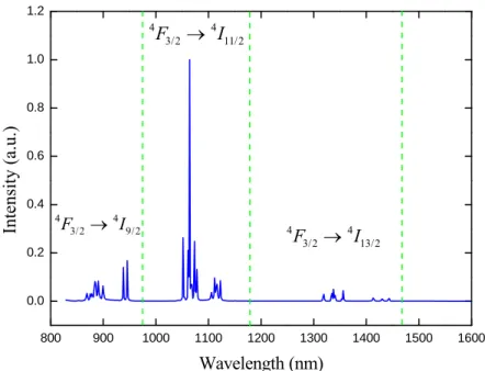
(25) The energy levels of the rare-earth elements (Nd3+) split into a number of Stark levels due to the action of the crystal field.. The electron transition corresponding to. each Stark level emits a different wavelength. Fig. 1.2.3 depicts the energy level diagram of Nd:YAG laser medium and Stark splitting of the manifolds are shown. Laser transition lines of 946, 1064, 1319, and 1338 nm are indicated.. The laser. transitions occur between the individual Stark sublevels of different manifolds. Figure 1.2.4 shows the measured results for the fluorescence spectrum of Nd3+ in YAG with the corresponding energy levels for the various transitions. It can be clearly seen Nd3+ in YAG additionally provides the long wavelengths end of the 4F3/2 → 4I13/2 transition around 1.41−1.44 μm.. The effective stimulated-emission cross. section is the spectroscopic cross section times the occupancy of the upper laser level relative to the entire 4F3/2 manifold population.. In 1974, Singh et al. have been. measured the stimulated-emission cross section at room temperature [6], as listed in Tab. 1.2.1. In Nd:YAG crystal, the 1064 nm transitions 4F3/2 → 4I11/2 have the highest emission cross sections at room temperature.. Several low-gain transitions,. one at 946 nm and two at 1.3 μm, are of particular interest in Nd:YAG because frequency doubling of these wavelengths is attractive for generating visible lasers in the blue and red region.. Other low-gain transitions at around 1.44 μm are of. particular interest in the eye-safe laser range.. To achieve these low-gain transitions,. parasitic oscillations at the higher gain transitions have to be suppressed. It is worth mentioning that the laser operating at 946 nm emission is termed a quasi-three-level laser. Since the lower laser level is only ~ 4 kT (853 cm−1) above the ground state [6], there is a thermal population of about 0.7% at room temperature [3].. This residual population results in a partial reabsorption loss of the laser. radiation which increases the laser threshold. Simplified energy level diagrams of a four-level laser and a quasi-three-level laser are depicted in Fig. 1.2.5.. In a. four-level system, the lower laser level is above the ground state by an energy gap E. k BT. , and therefore is not thermally populated.. Compared to the four-level lasers,. the quasi-three-level and three-level lasers require high pump intensities to generate population inversion.. 6 .
(26) Fig. 1.2.3.. Energy level diagram of Nd:YAG. The solid line represents the major transition. at 1064 nm, and the dashed lines are the transitions at 1319, 1338, and 946 nm [3].. 7 .
(27) 1.2 4. F3/2 → 4 I11/2. 1.0. Intensity (a.u.). 0.8. 0.6. 0.4 4. F3/2 → 4 I 9/2. 4. 0.2. F3/2 → 4 I13/2. 0.0 800. 900. 1000. 1100. 1200. 1300. 1400. 1500. 1600. Wavelength (nm). Fig. 1.2.4.. Measured results for the fluorescence spectrum of Nd3+ in YAG.. 8 .
(28) Tab. 1.2.1.. The stimulated-emission cross section of the various laser transitions in. Nd:YAG at room temperature [6].. 9 .
(29) (a). (b). Fig. 1.2.5.. Simplified energy level diagrams of (a) a four-level laser system and (b) a. quasi-three-level laser system.. N1 and N2 are the populations of the lower laser level and the. upper laser level, respectively.. 10 .
(30) 1.3 Passively QSwitched Lasers [3] Q switching is a technique for the generation of nanosecond pulses of high energy and peak power laser pulses by modulating the Q factor of the laser resonator with a saturable absorber. Fig. 1.3.1 shows the generation of a Q-switched laser pulse.. Laser inversion is built up by the pumping process and laser oscillation begins. to develop inside the cavity. cavity is opened up.. While the laser oscillation saturates the absorber, the. Simultaneously, the laser inversion exceeds the cavity losses,. and then a short pulse is rapidly emitted. The Q-switched pulse duration is typically in the nanosecond range, corresponding to several cavity round trips. Passively Q-switched (PQS) lasers are of many practical applications such as laser ranging, laser cutting and drilling, and nonlinear optical studies.. Passive. Q-switching that uses an internal saturable absorber has the advantages of simplicity, compactness, and low cost, and requires no external driving circuitry. Numerous saturable absorbers have been developed, such as dyes [7], LiF:F2-color center crystals [8,9], and Cr4+:YAG crystals [10-16].. Nowadays, Cr4+:YAG crystal is the. popular saturable absorber in the spectral region of 0.9−1.2 μm . Because of its better thermo-mechanical properties, stability, reliability and simplicity, it is especially suitable for all-solid-state laser systems.. An attractive alternative is the use of. semiconductor saturable absorbers which saturation fluence and maximum modulation depths can be flexibly designed, and they can be adapted to different laser wavelengths.. To date, semiconductor saturable absorbers have been demonstrated as. useful devices for solid-state lasers [17-20].. 11 .
(31) (a) inversion. cavity loss. photon. time. (b). Fig. 1.3.1.. Schematic illustration of (a) the repetitive Q-switching and (b) development of a. Q-switched laser pulse.. 12 .
(32) 1.4 Nonlinear Optics[21,22] v. A nonlinear optical effect can occur when the electric field E of electromagnetic v. wave is increased significantly to induce nonlinearity in the polarization vector P in a material. The relationship between P and the applied electric field E is expressed P = ε 0 χ (1) E + ε 0 χ ( 2) E 2 + ε 0 χ (3) E 3 + L. (1). where ε0 is the permittivity of free space and χ(1) is the linear susceptibility representing the linear response of the material. nonlinear response of the medium.. The other terms describe the. The term in E2 is called the second-order. nonlinear response and χ(2) is called the second-order nonlinear susceptibility. Similarly, the term in E3 is called the third-order nonlinear response and χ(3) is called the third-order nonlinear susceptibility. The magnitudes of the nonlinear susceptibility coefficients are such that the second- and third-order polarizations become comparable to the linear polarization (1) term P1 = ε 0 χ E when the applied electric field E is of the order of the electric field 2 produced between the electron and proton of a hydrogen atom, E ≈ e / (4πε 0 aH ) , where. e is the electron charge, aH is the radius of the electron orbit. χ(2) and χ(3) are of the order of χ (2) ≈ 2 × 10⁻¹¹ m/V. (2). χ (3) ≈ 4 × 10⁻²³ m/V. (3). and. respectively [22]. Numerous nonlinear processes that use laser radiation to generate new frequencies of coherent light and produce other interesting nonlinear effects. Second-order nonlinear phonomena related to χ(2) describe three-wave mixing processes, including second harmonic generation (SHG), sum frequency generation. 13 .
(33) (SFG), different frequency generation (DFG), and optical parametric generation (OPG).. Second harmonic generation is a special case of sum frequency generation.. Figure 1.4.1 depicts the second-order nonlinear processes.. The third order. nonlinearities involved χ(3) is thus four-wave mixing processes, including third harmonic generation, optical Kerr effect, Raman effect, and Brillouin scattering. Not all wavelength regions of interest are directly accessible with lasers. Nonlinear frequency conversion is an important method of extending the frequency range of available laser sources.. Many industrial, medical, and military. applications require a different wavelength than the fundamental output available from standard lasers. Medical applications require solid-state lasers operating in a specific spectral range for control of the absorption depth of the radiation in the skin, tissue, or blood vessels.. Military rangefinders need to operate in a region. (wavelength > 1.5 μm) that does not cause eye damage because most of the time these systems are employed in training exercises.. Therefore, diode-pumped. solid-state laser combines with nonlinear optical frequency conversion technology will extend wider wavelength region.. 14 .
(34) Fig. 1.4.1.. (a). (b). (c). (d). Schematic of second-order nonlinear processes: (a) second harmonic generation. (SHG), (b) sum frequency generation (SFG), (c) different frequency generation (DFG), and (d) optical parametric generation (OPG).. 15 .
(35) 1.5 Overview of Thesis In the thesis, various laser emissions in Nd-doped crystals and wavelength conversion with nonlinear optics are the main goal.. Besides, high-pulse-energy. lasers generation is an additional goal. Therefore two pump source, including CW fiber-coupled laser diode and QCW two dimensional laser diode stacks, are used in laser experiments.. The main text of this thesis is organized as following.. Laser operation on the transition 4F3/2 →4F9/2 of Nd3+ ions generates wavelengths of 910 to 950 nm and allows for SHG into the blue spectrum region. End pumping is especially good for quasi-three-level operation, because of the high pump intensity in laser crystal. In chapter 2, we realize a quasi-three-level 946 nm Nd:YAG laser and blue light generation at 473 nm by intracavity frequency doubling.. For the low gain. Nd:YAG laser at 946 nm, we develop a semiconductor quantum-wells saturable absorber with low nonsaturable losses.. Furthermore, we make a thorough. comparison for the 946-nm passively Q-switched performance between the saturable absorbers of the semiconductor quantum-wells saturable absorber and the Cr4+:YAG crystal.. In order to generate a higher-power 946 nm Nd:YAG laser and a blue light at. 473 nm, a high-power quasi-continuous-wave (QCW) diode stack is used as a pump source. SESAM is not only used to be an absorber element for passively Q-switched laser, but also to be a novel intracavity selective absorber (ISA) used for suppressing high-gain lines.. In chapter 3, we report an ISA with an AlGaInAs QW–barrier. structure grown on a Fe-doped InP transparent substrate.. With the novel ISA, an. efficient high-power Nd:YAG laser at 1.44 μm is successfully realized. Nd3+-doped lasers operating at 1.0 μm have been maturely developed for many years and possess superior performances.. In chapter 4, eye-safe wavelength is. obtained from Nd3+-doped lasers that are wavelength-shifted with an optical parametric oscillator (OPO).. Efficient eye-safe lasers with mJ pulse energy are. studied for military requirement.. We theoretically and experimentally study the. output performance of an intracavity OPO in a shared cavity configuration. Besides, we present an analytical design model to investigate the dynamics of simultaneous. 16 .
(36) emission of fundamental and signal waves. Furthermore, we design an AlGaInAs QW material with a low nonsaturable loss and large modulation strength to be a saturable absorber used in an intracavity Nd:YVO4/KTP optical parametric oscillator. In the previous chapter, a plane-parallel configuration generates a high-energy laser but leads to a large beam divergence and poor beam quality. In chapter 5, to improve the beam quality and accomplish efficient energy extraction, we design an unstable convex-concave resonator stabilized by thermal-lensing effect to generate a large fundamental mode volume in a passively Q-switched laser.. By using ABCD. law and the complex beam parameter q, the laser mode size is analyzed. Based on the unstable cavity, a passively Q-switched Nd:YAG/ Cr4+:YAG laser with a large fundamental mode volume and good beam quality is experimentally confirmed.. 17 .
(37) References [1]. Z. J. Kiss, and R. J. Pressley, “Crystalline solid lasers,” Appl. Opt. 5, 1474-1486 (1966).. [2]. D. Meschede, Optics, light and lasers: the practical approach to modern aspects of photonics and laser physics, Physics Textbook, first ed., (Wiley-VCH, Weinheim , 2004). [3]. W. Koechner, Solid-state laser engineering, Optical Sciences, 6th ed., (Springer, Berlin, 2006).. [4]. Y. Kaneda, M. Oka, H. Masuda, and S. Kubota, “7.6 W of continuous-wave radiation in a TEM00 mode from a laser-diode end-pumped Nd:YAG laser,” Opt. Lett. 17, 1003-1005 (1992).. [5]. T. Kellner, F. Heine, and G. Huber, “Efficient laser performance of Nd:YAG at 946 nm and intracavity frequency doubling with LiJO3, -BaB2O4, and LiB3O5,” Appl. Phys. B 65, 789-902 (1997).. [6]. S. Singh, R. G. Smith, and L. G. Van Uitert, “Stimulated-emission cross section and fluorescent quantum efficiency of Nd3+ in yttrium aluminum garnet at room temperature,” Phys Rev B 10, 2566-2572 (1974).. [7]. S. Y. Lam, and M. J. Damzen, “Characterisation of solid-state dyes and their use as tunable laser amplifiers,” 77, 577-584 (2003).. [8]. A. G. Kalinstev, A. A. Mak, L. N. Soms, A. I. Stepanov, and A. A. Tarasov, “Residual losses in passive shutters made from Li crystals with color centers,” Sov. Phys. Tech. Phys. 26, 1267-1268 (1981).. 18 .
(38) [9]. T. T. Basiev, S. V. Vassiliev, V. A. Konjushkin, and V. P. Gapontsev, “Pulsed and cw laser oscillations in LiF : F-2(-) color center crystal under laser diode pumping,” Opt. Lett. 31, 2154-2156 (2006).. [10] Y. F. Chen, S. W. Tsai, and S. C. Wang, “High-power diode pumped Q-switched and mode-locked Nd:YVO4laser with a Cr4+:YAG saturable absorber,” Opt. Lett 25, 1442-1444 (2000). [11] J. Liu, J. M. Yang, and J. L. He, “High repetition rate passively Q-switched diode-pumped Nd:YVO4 laser,” Opt. Laser Technol. 35, 431-434 (2003). [12] Y. Kalisky, “Cr4+-doped crystals: their use as lasers and passive Q switches,” Prog. Quantum Electron. 28, 249-303 (2004). [13] H. Chen, E. Wu, and H. P. Zeng, “Comparison between a-cut and off-axially cut Nd:YVO4 lasers passively Q-switched with a Cr4+:YAG crystal,” Opt. Commun. 230, 175-180 (2004). [14] A. Sennaroglu, U. Demirbas, S. Ozharar, and F. Yaman, “Accurate determination of saturation parameters for Cr4+-dpoed solid-state saturable absorbers,” J. Opt. Soc. Am. B 23, 241-249 (2006). [15] S. Forget, F. Druon, F. Balembois, P. Georges, N. Landru, J.-P. Fève, J. Lin, and Z.. Weng,. “Passively. Q-switched. diode-pumped. Cr4+:YAG/Nd3+:GdVO4. monolithic microchip laser,” Opt. Commun. 259, 816-819 (2006). [16] A. R. Bijanzaden, and R. Khordad, “Study of output energy of Cr4+:YAG passively Q-switched Nd:YAG laser: using different setup,” Opt. Commun. 282, 2595-2603 (2009). [17] G. J. Spühler, R. Paschotta, R. Fluck, B. Braun, M. Moser, G. Zhang, E. Gini, and U. Keller, “Experimentally confirmed design guidelines for passively. 19 .
(39) Q-switched microchip lasers using semiconductor saturable absorbers,” J. Opt. Soc. Am. B 16, 376-388 (1999). [18] R. Häring, R. Paschotta, R. Fluck, E. Gini, H. Melchior, and U. Keller, “Passively Q-switched microchip laser at 1.5 μm,” J. Opt. Soc. Am. B 18, 1805-1812 (2001). [19] G. J. Spühler, S. Reffert, M. Haiml, M. Moser, and U. Keller, “Output-coupling semiconductor saturable absorber mirror,” Appl. Phys. Lett. 78, 2733-2735 (2001). [20] B. Y. Zhang, G. Li, M. Chen, G. J. Wang, and Y. G. Wang, “Passively Q-switched Nd :GdVO4 laser with In0.25Ga0.75As being an output coupler,” Opt. Laser Technol. 39, 1094-1097 (2007). [21] M. Fox, Quantum optics: an introduction, Atomic, Optical, and Laser Physics, first ed., (Oxford, New York, 2006). [22] W. T. Silfvast, Laser Fundamentals, Optics, 2 nd ed., (Cambridge, New York, 2004).. 20 .
(40) Chapter 2 DiodePumped Nd:YAG Laser at 0.946 μm and Intracavity Frequency Doubling . 2.1 ContinuousWave Nd:YAG Laser at 946 nm and Intracavity Frequency Doubling to 473 nm Fan and Byer first demonstrated the quasi-three-level laser operating at 946 nm [1]. The 4F3/2→ 4I9/2 transition has its lower laser level in the thermally populated ground state, which is only 4 kT above the ground state at room temperature [2], leading to temperature-dependent reabsorption losses.. In addition, the stimulated. emission cross section of 946 nm is smaller than 1064 nm (around 9 times). Nd-doped lasers around 0.9 μm are much attractive for frequency doubling into the blue range.. The second-harmonic generation of continuous-wave (cw) 946-nm. lasers is useful for applications such as holography, optical data storage, and color displays. Various nonlinear crystals are utilized for the frequency-doubling of the 946-nm Nd:YAG lasers, such as KN (KNbO3), PPKTP (periodically poled KTiOPO4), LBO (LiB3O5), BBO (β-BaB2O4), and BiBO (BiB3O6) [3-8].. Among biaxial crystals,. BiBO crystal has a high optical damage threshold and many advantages for nonlinear optics, such as large effective nonlinear coefficient, large angular and spectral acceptance bandwidths, and broadband angle tuning at room temperature [9].. 21 . The.
(41) most important is that BiBO crystal is non-hygroscopic, and therefore it is favorable for many optical devices and applications.. 2.1.1 Experimental Setup The active medium was 1.1 at.% Nd:YAG crystal with a length of 2.0 mm. Since a short crystal length was used to reduce the reabsorption losses, only approximately 52% of the pump light was absorbed in the gain medium.. In order to. shorten the cavity length, the entrance surface of the laser crystal was coated to be high reflection at 946 nm (R>99.8%) and high transmission at 808 nm (T>90%) and 1064 nm (T>85%).. The other surface of the laser crystal was coated for. antireflection at 946 nm (R<0.2%). Note that for this low-gain 946 nm laser, tough coating is demanded to suppress the competing transition lines of 1064 nm and 1320 nm.. The transmittance spectrum for the entrance surface of the Nd:YAG crystal eas. shown in Fig. 2.1.1. Figure 2.1.2 (a) shows the schematic diagram of cw 946 nm Nd:YAG laser. The pump source was a 10-W 808-nm fiber-coupled laser diode with a core diameter of 600 μm and a numerical aperture of 0.16. Focusing lens with 5 mm focal length and 92% coupling efficiency was used to re-image the pump beam into the laser crystal.. The pump spot radius was approximately 160 μm.. The output couplers. were flat and coated for high transmission at 1064 nm (T>90%) and partial reflection at 946 nm (R=97%, 96% and 93%, respectively).. The cavity length was. approximately 10 mm. Figure 2.1.2(b) shows the experimental configuration of cw intracavity frequency-doubled Nd:YAG laser. The frequency doubler we used was a 2×2×5 mm3 BiBO crystal, which is cut for type-I critical phase-matching (θ=161.7o, φ=90o). Both facets of the BiBO crystal were coated for anti-reflection at 946 and 473 nm (R<0.2%) to reduce the reflection loss in the cavity.. The laser crystals were wrapped. with indium foil and mounted in a water-cooled copper block.. A plano-concave. mirror of 50 mm radius was chosen to be the output coupler coated for high reflection at 946 nm (R>99.8%), high transmission at 1064 nm (T >70%), and high transmission. 22 .
(42) at 473 nm (T>80%), respectively. The cavity length was approximately 30 mm.. 23 .
(43) 100 90. Transmission (%). 80 70 60 50 40 30 20 10 0 800. 850. 900. 950 1000 1050 1100 1150 1200 1250 1300 1350 1400. Wavelength (nm). Fig.2.1.1.. Transmittance spectrum for the entrance surface of the Nd:YAG crystal: high. reflection at 946 nm (R>99.8%) and high transmission at 808 nm (T>90%) and 1064 nm (T>85%).. 24 .
(44) (a). (b). Fig.2.1.2. Experimental setup for (a) diode-pumped Nd:YAG laser.; (b) diode-pumped intracavity frequency-doubled 473 nm Nd:YAG /BiBO blue laser.. 25 .
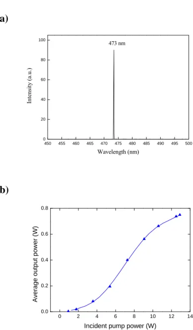
(45) 2.1.2 Experimental Results and Discussion First of all, the 946-nm cw laser was performed to confirm the quality of the laser crystal.. Fig. 2.1.3 plots the cw average output power at 946 nm with respect to the. incident pump power at 808 nm.. It could be seen that the slope efficiency of three. output couplers are nearly similar to be 18%.. The optimal output reflectivity for cw. output power is 97%. At an incident power of 19.6 W, the maximum output power can be up to 3 W with an optical-to-optical conversion efficiency of 15%. Employing the above-mentioned plano-concave mirror of 50 mm radius, the second harmonic generation (SHG) of 946-nm laser with a BiBO crystal was performance. Fig. 2.1.4 (a) shows the spectral information of the laser monitored by an optical spectrum analyzer (Advantest Q8381A) with the resolution of 0.1 nm.. Fig.. 2.1.4 (b) shows the cw output average power as a function of the incident pump power at 808 nm.. At a pump power of 13 W, the cw output average power at 473 nm was. 0.75 W, with a SHG conversion efficiency of 35%.. 26 .
(46) Average output powerat 946 nm (W). 3.0. R=97 % R=95 % R=93 %. 2.5 2.0 1.5 1.0 0.5 0.0 0. 2. 4. 6. 8. 10. 12. 14. 16. 18. 20. Incident pump power (W). Fig. 2.1.3.. CW average output power at 946 nm with respect to the incident pump power.. 27 .
(47) (a) 100. 473 nm. Intensity (a.u.). 80. 60. 40. 20. 0 450. 455. 460. 465. 470. 475. 480. 485. 490. 495. 500. Wavelength (nm). (b). Average output power (W). 0.8. 0.6. 0.4. 0.2. 0.0 0. 2. 4. 6. 8. 10. 12. 14. Incident pump power (W). Fig. 2.1.4.. (a) Optical spectrum of the blue laser; (b) CW average output power at 473 nm. with respect to the incident pump power.. 28 .
(48) 2.2 Efficient Passively QSwitched Nd:YAG Laser at 946 nm Passively Q-switched all-solid-state lasers are of great interest because of their potential applications in remote sensing, ranging, micromachining, and nonlinear wavelength conversion.. The majority of the work on the Nd:YAG crystal were. focused on the 4F3/2→4I11/2 transition in the 1064-nm range.. Nevertheless, the lasing. wavelength near 946 nm in the 4F3/2→4I9/2 transition has attracted much attention during the last decade [10-17], since it is of interest for second-harmonic generation into the blue region. Kellner et al. employed a Cr4+:YAG crystal as a saturable absorber in a passively Q-switched 946-nm Nd:YAG laser to achieve as much as 1.6-W average output power with pulse width of 70-100 ns [12].. Recently, Zhang et. al. demonstrated an average output power of 2.1 W with pulse width of 40.8 ns by using a Nd, Cr:YAG saturable absorber [13].. More recently, Wang et al. used a. GaAs saturable absorber to obtain an average output power of 1.24 W with pulse width of 70 ns [14].. However, so far the overall Q-switching efficiencies (ratio of. the Q-switched average output power to the cw output power at the same pump power) were in the range of 30-50%.. The low Q-switching efficiencies arise from the. nonsaturable losses of the saturable absorbers. Since the gain of the Nd:YAG crystal at 946 nm is quite low, a small amount of nonsaturable losses may lead to a considerable reduction in the efficiency.. In view of that, it is of practical usefulness. to develop a saturable absorber with low nonsaturable losses for the low gain Nd:YAG laser at 946 nm.. 2.2.1 Design of Semiconductor Saturable Absorbers The present saturable absorber was fabricated to combine a SESAM with an output coupler (SESAMOC) that was originally proposed by Spühler et al. to simplify the cavity configuration in passively Q-switched lasers [18]. The SESAMOC device, as shown in Fig. 2.2.1, was monolithically grown on an undoped 350 μm thick GaAs substrate by metalorganic chemical vapor deposition (MOCVD) to comprise three strained InGaAs/GaAs QWs grown on the Bragg mirror. The QWs have a thickness. 29 .
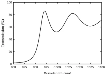
(49) of 8 nm and are separated by 10 nm thick GaAs layers.. The Bragg mirror consists of. eleven AlAs/GaAs quarter-wavelength layers, designed for a reflectivity in the region of 97~98% at 946 nm.. The back side of the GaAs substrate was coated for. antireflection at 946 nm (R<1%). Figure 2.2.2 shows the measured result for the low-intensity transmission spectrum of the SESAMOC.. It can be seen that the. low-intensity transmission was approximately 1.5% at 946 nm and 56% at 1064 nm. The experimental result of the room-temperature photoluminescence (PL) spectrum is depicted in Fig. 2.2.3.. The peak wavelength of the PL spectrum is found to be in the. vicinity of 946 nm and the full-width at half maximum (FWHM) is approximately 20 nm.. The saturation measurements were performed using nanosecond Q-switched. laser pulses to coincide with the present Q-switched experiment.. Experimental. results revealed that the present SESAM device had a modulation depth of 1.5% and a saturation fluence of 20 μJ/cm2.. 30 .
(50) Fig. 2.2.1.. The structure of the InGaAs SESAMOC.. 31 .
(51) 100. Transmission (%). 80. 60. 40. 20. 0 900. 925. 950. 975. 1000. 1025. 1050. 1075. 1100. Wavelength (nm). Fig. 2.2.2.. Measured results for the low-intensity transmission spectrum.. 32 .
(52) Photoluminescence intensity (arb. units). 1.2. 1.0. 0.8. 0.6. 0.4. 0.2. 0.0 900. 920. 940. 960. 980. 1000. Wavelength (nm). Fig. 2.2.3.. Room-temperature photoluminescence (PL) spectrum of the InGaAs QWs. saturable absorber.. 33 .
(53) 2.2.2 Experimental Setup Figure 2.2.4 shows the experimental configuration of the passively Q-switched 946 nm Nd:YAG laser with InGaAs QWs as a SESAMOC. 1.1 at.% Nd:YAG crystal with a length of 2.0 mm.. The active medium was. The entrance surface of the laser. crystal was coated to be high reflection at 946 nm (R>99.8%) and high transmission at 808 nm (T>90%) and 1064 nm (T>85%).. The other surface of the laser crystal was. coated for antireflection at 946 nm (R<0.2%). The laser crystal was wrapped with indium foil and mounted in a water-cooled copper block. The pump source was a 10-W 808-nm fiber-coupled laser diode with a core diameter of 600 μm and a numerical aperture of 0.16.. Focusing lens with 5 mm focal length and 92% coupling. efficiency was used to re-image the pump beam into the laser crystal. radius was approximately 160 μm.. The pump spot. The cavity length was approximately 15 mm.. The spectral information of the laser was monitored by an optical spectrum analyzer (Advantest Q8381A).. The spectrum analyzer employing diffraction lattice. monochromator can be used for high-speed measurement of pulse light with the resolution of 0.1 nm.. The pulse temporal behavior was recorded by a LeCroy digital. oscilloscope (Wavepro 7100, 10 G samples/sec, 1 GHz bandwidth) with a fast PIN photodiode.. 34 .
(54) Fig. 2.2.4.. Schematic of a diode-pumped passively Q-switched Nd:YAG laser at 946 nm.. 35 .
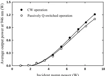
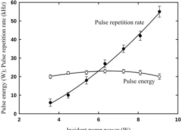
(55) 2.2.3 Experimental Results and Discussion The average output powers at 946 nm with respect to the incident pump power in the passively Q-switching operation are depicted in Fig. 2.2.5, and the optimum cw performance with the optimum reflectivity of the output coupler of 97% is shown for comparison.. The output power in the CW operation reached 1.21 W at an incident. pump power of 9.2 W.. In the passively Q-switching regime an average output power. of 1.1 W was obtained at an incident pump power of 9.2 W.. Experimental results. indicate that the Q-switching efficiency (ratio of the Q-switched output power to the cw one at the maximum pump power) exceed 90%.. The extremely high Q-switching. efficiency signifies the nonsaturable losses of the present SESAMOC to be considerably low. Fig. 2.2.6 shows the pulse repetition rate and the pulse energy versus the incident pump power.. It was found that the pulse repetition rate was linearly proportional to. the pump power and approximately reached 55 kHz at an incident pump power of 9.2 W.. Like typically passively Q-switched lasers, the pulse energy is almost unrelated. to the pump power and its value is 20 μJ on average. On the whole, the pulse duration was approximately 38 ns.. With the measured pulse energy and pulse width,. the peak power can be found to be up to 0.53 kW.. A typical oscilloscope trace of a. train of output pulses and an expanded shape of a single pulse are shown in Fig. 2.2.7. Under the optimum alignment condition, the pulse-to-pulse amplitude fluctuation was less than ± 5% for the pump power lower than 6 W and within ± 15% at the maximum pump power of 9.2 W.. 36 .
(56) Average output power at 946 nm (W). 1.5. CW operation Passively Q-switched operation. 1.2. 0.9. 0.6. 0.3. 0.0 0. 2. 4. 6. 8. 10. Incident pump power (W). Fig. 2.2.5.. The average output powers at 946 nm with respect to the incident pump power. in CW and passively Q-switching operations.. 37 .
(57) Pulse energy (W); Pulse repetition rate (kHz). 60. Pulse repetition rate. 50. 40. 30. 20. Pulse energy. 10. 0 2. 4. 6. 8. 10. Incident pump power (W). Fig. 2.2.6. Experimental results for pulse repetition rate and pulse energy versus incident pump power.. 38 .
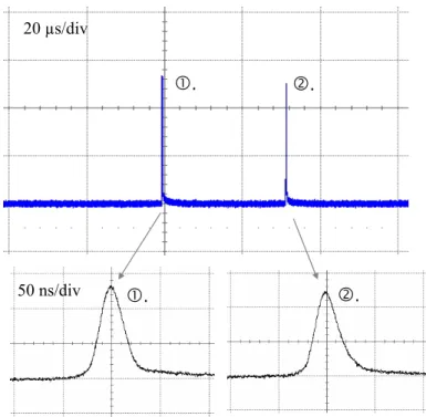
(58) Fig. 2.2.7.. (a). 50 μs/div. (b). 50 ns/div. (a) Typical oscilloscope trace of a train of output pulses and (b) expanded shape. of a single pulse.. 39 .
(59) 2.3 HighPower 946 nm Nd:YAG Laser and Blue Laser at 473 nm in QCW operation With the rapid development of laser diode, high-power 2 D laser diode arrays (LDA) or diode stacks have been used in diode-pumped solid-state lasers to generate high output pulse energies in free-running or Q-switched operations for several years. Compared with the conventional high-power pump source, flash lamps, the 2D diode stacks, consisting of several diode bars, possess many advantages of higher repetition rates, higher overall efficiency, much lower thermal loading, and higher reliability. High-power diode stacks are operated in the pulse durations of several hundred micro-seconds, i.e. quasi-cw (QCW) operations, and emit high peak powers (on-time average powers) of several hundred watts. The QCW pumping technique provides not only the high-level power but also the average heat-loading reduction. In this part, we used a 2D diode stack in QCW operation as the pump source. A high-power, QCW diode-pumped Nd:YAG laser operating at 946 nm and its intracavity frequency doubling to 473 nm with a BiBO crystal were demonstrated.. 2.3.1 High‐Power QCW pump source Here, the pump source is a high-power QCW diode stack (Quantel laser diodes) that consists of three 10-mm-long diode bars generating 130 W per bar, for a total of 390 W at the central wavelength of 808 nm. The diode stack is designed with 0.4 mm spacing between the diode bars so the overall area of emission is approximately 10 mm (slow axis) × 0.8 mm (fast axis).. The images of the diode stack are shown in. Fig. 2.3.1. The full divergence angles in the fast and slow axes are approximately 35o and 10o, respectively.. This divergence causes a great loss of pump power.. Therefore, the highly efficient and simple optical devices, coupling the output from a laser diode stack into a gain medium, are especially important for the design of high power lasers with large laser diode stack as the pump source. A lens duct was reported to have good coupling efficiency and was used to. 40 .
(60) end-pump solid-state lasers [19, 20].. The lens duct is a glass device that can consist. of one spherical input surface and five planar surfaces, as shown in Fig. 2.3.2 (a). The spherical surface is designed for efficient collection of the output radiation from a laser diode stack into the duct. in Fig. 2.3.3.. Schematic of ray tracing inside a lens duct is depicted. The light rays are totally reflected from the four side surfaces until. they reach the planar output surface, and then injected into the gain medium.. The. output surface of lens duct has to adjoin the gain medium to reduce the coupling loss. Fig. 2.3.2 (b) shows the lens duct assembly.. For practical reasons the lens duct has. to be made of two pieces glued together. The first piece is a slice of a commercial plano–cylindrical lens, which provides the curved face.. The second piece is a lens. duct all of whose faces are plane. The curved surface of the plano–cylindrical lens and the lens duct output face are not antireflection coated. In comparison with other coupling methods such as optical fibers [21], gradient-index (GRIN) lenses [22], or aspheric lenses [23], the lens duct has the benefits of simple structure, high coupling efficiency, and impervious to slight misalignment.. These benefits are practically important for the end-pumped. solid-state lasers with laser-diode stacks in which there is a significant geometric mismatch between the effective diode emitter area and the available input aperture of the gain medium.. 41 .
(61) (a). (b). Fig. 2.3.1.. (a) Image of the Quantel laser diode and (b) the near-field image of laser diode. emitters at 30 A.. 42 .
(62) (a). L H1. r. H2 H3. (b). Fig. 2.3.2.. (a) Schematic of a lens duct with five geometric parameters of r, L, H1, H2, and. H3: r is the radius of the input surface, L is the length of the duct, H1 is the width of the input surface, H2 is the width of the output surface, and H3 is the thickness of the duct. (b) Lens duct assembly.. 43 .
(63) (a). (b). Fig. 2.3.3.. Schematic of ray tracing inside a lens duct: (a) top view in the slow-axis plane. [20], (b) side view in the fast-axis plane.. 44 .
(64) 2.3.2 Experimental Setup In this experiment, the lens ducts were manufactured with the same parameters of r = 10 mm, L = 30 mm and H1 = 12 mm, but the various output cross-sections with H2 × H3 at mm2 of 2.1×2.1, 1.6×1.6 and 1.2×1.2, respectively. The coupling efficiencies of three lens ducts were experimentally found to be approximately 86, 78, and 72%, respectively. The active medium was 3×3×5 mm3 Nd:YAG crystal with 1.1 at.%. Approximately 75% of the pump light was absorbed in the active medium.. The. entrance surface of the laser crystal was coated with high reflection at 946 nm (R>99.8%) and high transmission at 808 nm (T>90%) and 1064 nm (T>85%).. The. other surface of the laser crystal was coated for antireflection at 946 nm (R<0.2%). Fig. 2.3.4 (a) shows the schematic diagram of QCW 946 nm Nd:YAG laser. The output couplers were flat and coated for high transmission at 1064 nm (T>90%) and partial reflection at 946 nm (R=97%). The cavity length was approximately 10 mm.. Fig. 2.3.4 (b) shows the experimental configuration of cw intracavity. frequency-doubled Nd:YAG laser.. The frequency doubler was a 5-mm-long BiBO. crystal, cutting for type-I critical phase-matching (θ=161.7o, φ=90o) at room temperature. Both facets of the BiBO crystal were coated for anti-reflection at 946 and 473 nm (R<0.2%) to reduce the reflection loss in the cavity.. The laser crystals. were wrapped with indium foil and mounted in a water-cooled copper block.. A. plano-concave mirror of 50 mm radius was chosen to be the output coupler coated for high reflection at 946 nm (R>99.8%), high transmission at 1064 nm (T >70%), and high transmission at 473 nm (T>80%), respectively.. The SHG cavity length of was. approximately 30 mm. The pulse temporal behavior was recorded by a LeCroy digital oscilloscope (Wavepro 7100; 10 G samples/sec; 1 GHz bandwidth) with a fast InGaAs photodiode. The spectral information of the laser was monitored by an optical spectrum analyzer (Advantest Q8381A).. The spectrum analyzer employing diffraction grating. monochromator can be used for high-speed measurement of pulse light with the resolution of 0.1 nm.. 45 .
(65) (a). (b). Fig. 2.3.4.. Schematics of QCW diode-pumped Nd:YAG lasers at 946 nm in (a), and. intracavity frequency-doubling at 473 nm in (b).. 46 .
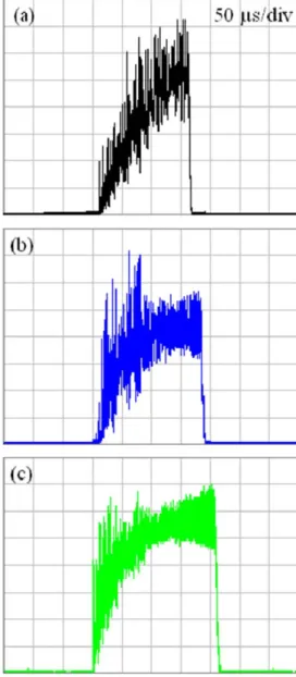
(66) 2.3.3 Experimental Results and Discussion First of all, the QCW free running operation of the Nd:YAG laser at 946 nm was measured without the BiBO crystal in the cavity to confirm the pump efficiency of the lens duct and the quality of the laser crystal.. In this experiment, the laser-diode stack. was set to emit pump pulses of 270 µs at a repetition rate of 35 Hz, as the duty cycle was approximately 1 %.. Three kinds of output cross-sections of lens ducts were. employed for comparisons in the quasi-continuous-wave free running operation. Fig. 2.3.5 (a) shows the experimental results of the output pulse energy at 946 nm with respect to the pump energy emitted from the laser diode in the free-running operation. It can be found that the lower pump threshold and higher output energy were achieved by employing a lens duct with a smaller output dimension.. With the lens duct with. the smallest output surface of 1.2×1.2 mm2, the lower pump threshold of 36 mJ and the maximum output pulse energy of 6.4 mJ were obtained at a pump energy of 105 mJ.. The experimental results confirm that a high-intensity pump light is necessary. for such quasi-three-level laser.. Note that the smallest dimension of a lens duct is. limited by the emission area of laser diode stack. Fig. 2.3.5 (b) depicts the pulse train at repetition rate of 35 Hz, at the maximum pump energy.. Fig. 2.3.6 (a)-(c). depict the temporal shapes of the single pulse exhibited relaxation-oscillation driven spikes for the employed lens ducts with output dimensions of 2.1×2.1, 1.6×1.6, and 1.2×1.2 mm2, respectively.. It can be seen that the relaxation-oscillation driven. spikes and the pulse shape of laser of a single pulse were dominated by the pump intensity. Moreover, due to the laser buildup time, the output laser pulse was shorter than the pump duration of 270 µs in the QCW operation.. The on-time average. output power can be estimated with the laser output pulse width and pulse energy. The on-time average output power at 946 nm versus the on-time average pump power is plotted in Fig. 2.3.7.. Using a lens duct with the output dimension of 1.2×1.2 mm2,. the maximum on-time average output power was 34 W at the on-time average pump power of 392 W.. The overall slope efficiency of the three curves were nearly similar. to be 13 %. The QCW diode-end-pumped Nd:YAG laser at 473 nm by intracavity frequency. 47 .
(67) doubling was operated by inserting a nonlinear crystal BiBO and replacing of the above mentioned concave mirror.. The experimental results of the output pulse. energy at 473 nm versus the pump energy are plotted in Fig. 2.3.8.. It reveals that the. pump intensity is extremely critical for an efficient SHG of the 946-nm low-gain laser. Using a lens duct with the output dimension of 1.2×1.2 mm2, the maximum output pulse energy of approximately 1.75 mJ was achieved for 105 mJ pump energy from the laser diode stack. Fig. 2.3.9 shows the estimated on-time average output power at 473 nm as a function of the on-time average pump power.. The maximum on-time. average output power at 473 nm of approximately 9 W was estimated at 392 W of the on-time average pump power.. The conversion efficiency of blue light at 473 nm. with respect to the average output power of the free running performance was greater than 26 %. To our best knowledge, it is the highest average power for intracavity frequency-doubling in the blue region at 473 nm of diode-end-pumped Nd:YAG laser. Fig. 2.3.10 (a)-(b) depict the pulse train and temporal shape of the single pulse at the maximum pump energy of 105 mJ by using a lens duct with the output dimension of 1.2×1.2 mm2.. Under the optimal alignment condition, the pulse-to-pulse amplitude. fluctuation was estimated to be approximately ±10 %. The spatial distribution of the output blue-light beam was recorded with a CCD as displayed in Fig. 2.3.10(c).. The. beam quality factors were measured and found to be M x2 < 12 and M y2 < 7, repetitively, where the x and y directions are parallel to the slow and fast axes of the laser-diode stack.. The asymmetry of the M 2 factors in the x and y directions was. due to the walk-off effect by nonlinear crystal.. 48 .
(68) (a). Output energy at 946 nm (mJ). 7. LensDuct 2.1x2.1 LensDuct 1.6x1.6 LensDuct 1.2x1.2. 6 5 4 3 2 1 0 0. 10. 20. 30. 40. 50. 60. 70. 80. 90. 100. 110. Pump energy at 808 nm (mJ). (b). Fig. 2.3.5. Experimental results of (a) the free-running operation for the output pulse energy nm versus pumpwith energy for threethe kinds outputinto surfaces of lens ducts, Fig. 8.at 946 Average output the powers, and without ISAof inserted the cavity with the OC1, the incident pump power. and (b) versus pulse train at the maximum pump energy.. 49 .
(69) Fig. 2.3.6. Temporal shapes of the single pulse for the lens duct output surface of (a) 2.1×2.1 mm2; (b) 1.6×1.6 mm2; (c) 1.2×1.2 mm2.. 50 .
(70) On-time output power at 946 nm (W). 40. LensDuct 2.1 x 2.1 LensDuct 1.6 x 1.6 LensDuct 1.2 x 1.2. 35 30 25 20 15 10 5 0 0. 50. 100. 150. 200. 250. 300. 350. 400. 450. On-time pump power at 808 nm (W). Fig. 2.3.7.. Estimated on-time average output power at 946 nm versus the on-time average. pump power in the free-running performance, for three kinds of output surfaces of lens ducts.. 51 .
(71) Output energy at 473 nm (mJ). 2.0 1.8. LensDuct 2.1x2.1 LensDuct 1.6x1.6 LensDuct 1.2x1.2. 1.6 1.4 1.2 1.0 0.8 0.6 0.4 0.2 0.0 0. 10. 20. 30. 40. 50. 60. 70. 80. 90. 100 110. Incident pump energy at 808 nm (mJ). Fig. 2.3.8. Experimental results of the free-running operation for the output pulse energy at 473 nm versus the pump energy for three kinds of output surfaces of lens ducts.. 52 .
(72) On-time output power at 473 nm (W). 10. LensDuct 1.2x1.2 8. 6. 4. 2. 0 0. 50. 100. 150. 200. 250. 300. 350. 400. On-time pump power at 808 nm (W). Fig. 2.3.9.. Estimated on-time average output power at 473 nm as a function of the on-time. average pump power for the lens duct with an output surface of 1.2×1.2 mm2.. 53 .
(73) (a). (b). (c). Fig. 2.3.10.. Experimental results for the lens duct with an output surface of 1.2×1.2 mm2:. (a) pulse train at the maximum pump energy of 105 mJ; (b) temporal shape of the single pulse at the maximum pump energy of 105 mJ; (c) Spatial distribution of the output blue beam recorded with a CCD.. 54 .
數據
![Tab. 1.2.1. The stimulated-emission cross section of the various laser transitions in Nd:YAG at room temperature [6]](https://thumb-ap.123doks.com/thumbv2/9libinfo/8118210.165796/28.892.184.718.328.633/stimulated-emission-cross-section-various-laser-transitions-temperature.webp)

+7
![Fig. 2.3.3. Schematic of ray tracing inside a lens duct: (a) top view in the slow-axis plane [20], (b) side view in the fast-axis plane](https://thumb-ap.123doks.com/thumbv2/9libinfo/8118210.165796/63.892.216.631.248.838/fig-schematic-tracing-inside-lens-duct-plane-plane.webp)
Outline
Overview of Thesis
Efficient Passively QSwitched Nd:YAG Laser at 946 nm
HighPower 946 nm Nd:YAG Laser and Blue Laser at 473 nm in QCW operation
HighPeakPower Passively QSwitched Nd:YAG Laser at 946 nm
High‐Power Continuous‐Wave Nd:YAG Laser at 1.44 µm
Subnanosecond EyeSafe Intracavity OPO
Analytical Model for Simultaneous Emission of Fundamental and Signal Waves
Efficient Intracavity OPO with an AlGaInAs QuantumWell (QW) Saturable Absorber
Results and Discussion
相關文件
A light beam incident on a small circular aperture becomes diffracted and its light intensity pattern after passing through the aperture is a diffraction pattern with circular
單晶片電路接受到 A/D 轉換器的信號後,即將此數位信號由顥示器 顯示。此時單晶片 IC 並將此一 A/D 轉換器與指撥設定開關做比較,A/D 轉換器的信號高於設定值時,即由 OUT CONTROL
本模組的編碼法適合 Command mode/Data mode 切換先連續發射 10 次 High、Low 信號作為前導波形接著發射起始波形 600 微秒 High→600 微秒 Low→600 微秒 High→400 微秒
In the algorithm, the cell averages in the resulting slightly non-uniform grid is updated by employing a finite volume method based on a wave- propagation formulation, which is very
* Anomaly is intrinsically QUANTUM effect Chiral anomaly is a fundamental aspect of QFT with chiral fermions.
由聲波的波形決 定,不同的人及 樂器產生的波形 都不同。.
(2)在土壤動力學中,地震或地表振動產生之振動波,可分為實 體波(Body wave) 與表面波(Surface wave) 。實體波(Body wave)分為壓力波 P 波(Compressional wave)(又稱縱波)與剪
而在利用 Autocloning 的方法,製作成金字塔形狀的抗反射 結構方面。分成非次波長結構和次波長結構來加以討論。在非次波長 結構時,我們使用
