Ultrahigh supermode noise suppressing ratio of a
semiconductor optical amplifier filtered
harmonically mode-locked Erbium-doped fiber
laser
Gong-Ru Lin*, Ming-Chung Wu,Yung-Cheng Chang, and Ci-Ling Pan *Department of Photonics & Institute of Electro-Optical Engineering, National Chiao Tung University
1001 Ta Hsueh Road, Hsinchu 300, Taiwan, Republic of China
grlin@faculty.nctu.edu.tw
Abstract: The supermode noise suppressing ratio (SMSR) and the phase noise of a harmonically mode-locked Erbium-doped fiber laser (HML-EDFL) with an intra-cavity semiconductor optical amplifier (SOA) and an optical band-pass filter (OBPF) are improved and compared with a state-of-the-art Fabry-Perot laser diode (FPLD) injection-mode-locked EDFL. By driving the intra-cavity SOA based high-pass filter at unitary gain condition, the SMSR of the HML-EDFL is enhanced to 82 dB at the cost of degrading phase noise, increasing jitter, and broadened pulsewidth. The adding of OBPF further improves the SMSR, pulsewidth, phase noise, and jitter of the SOA-filtered HML-EDFL to 90 dB, 42 ps, -112 dBc/Hz, and 0.7 ps, respectively. The ultrahigh SMSR of the SOA-filtered HML-EDFL can compete with that of the FPLD injection-mode-locked EDFL without sacrificing its pulsewidth and jitter performances.
©2005 Optical Society of America
OCIS codes: (140.4050) Mode-locked lasers; (250.5980) Semiconductor optical amplifier;
(140.3500) Lasers, erbium; (140.3520) Lasers, injection-locked
References and links
1. K. K. Gupta and D. Novak, “Millimeter-wave repetition-rate optical pulse train generation in harmonically
modelocked fiber ring laser,” Electron. Lett. 33, 1330-1331 (1997).
2. R. P. Davey, K. Smith, and A. McGuire, “High-speed mode-locked, tunable, integrated erbium fibre laser,”
Electron. Lett. 28, 428-483 (1992).
3. S. Kawanishi, K. Okamoto, M. Ishii, O. Kamatani, H. Takara, and K. Uchiyama, “All-optical
time-division-multiplexing of 100 Gbit/s signal based on four-wave mixing in a travelling-wave semiconductor laser amplifier,” Electron. Lett. 33, 976-977 (1997).
4. N. de Baynes, J. Allan, and J. R. A. Cleaver, “Mode-discriminating electrooptic sampling for separating guided
and unguided modes on coplanar waveguide,” IEEE Micro. Guided Wave Lett. 6, 126-128 (1996).
5. T. Papakyriakopoulos, K. Vlachos, A. Hatziefremidis, and H. Avramopoulos, “20-GHz broadly tunable and
stable mode-locked semiconductor amplifier fiber ring laser,” Opt. Lett. 24, 209-1211 (1999).
6. G.-R. Lin, Y. Liao, and G. Xia, “Dynamics of optical backward-injection-induced gain-depletion modulation and
mode locking in semiconductor optical amplifier fiber lasers,” Opt. Express 12, 2017-2026 (2004),
http://www.opticsexpress.org/abstract.cfm?URI=OPEX-12-10-2017.
7. S. Li and K. T. Chan, “Actively mode-locked erbium fiber ring laser using a Fabry–Perot semiconductor
modulator as mode locker and tunable filter,” Appl. Phys. Lett. 74, 2737-2740 (1999).
8. S. Li and K. T. Chan, “Wavelength-tunable actively mode-locked erbium-doped fiberring laser using a
distributed feedback semiconductor laser as mode locker and tunable filter,” Appl. Phys. Lett. 75, 313-315 (1999).
9. M. Jinno, “Effect of timing jitter on an optically-controlled picosecond optical switch,” Opt. Lett. 18, 1409-1411
(1993).
10. K. K. Gupta, D. Novak, and H.-F. Liu, “Noise characterization of a regeneratively mode-locked fiber ring laser,”
IEEE J. Quantum Electron. 36, 70-78 (2000).
11. E. Yoshida and M. Nakazawa, “Measurement of the timing jitter and pulse energy fluctuation of a PLL
regeneratively mode-locked fiber laser,” IEEE Photonics Technol. Lett. 11, 548-550 (1999).
12. M. Nakazawa, E. Yoshida, and K. Tamura, “10GHz, 2ps regeneratively and harmonically FM mode-locked
13. L. Duan, C. J. K. Richardson, Z. Hu, M. Dagenais, and J. Goldhar, “A stable smoothly wavelength-tunable picosecond pulse generator,” IEEE Photonics Technol. Lett. 14, 840-842 (2002).
14. M. Schell, W. Utz, D. Huhse, J. Kassner, and D. Bimberg, “Low jitter single-mode pulse generation by a
self-seeded gain-switched Fabry-Perot semiconductor laser,” Appl. Phys. Lett. 65, 3045-3047 (1994).
15. D. Von der Linde, “Characterization of the noise in continuously operating mode-locked laser,” Appl. Phys. B 39,
201-217 (1986).
16. M. J. W. Rodwell, D. M. Bloom, and K. J. Weingarten, “Subpicosecond laser timing stabilization,” IEEE J.
Quantum Electron. 25, 817-827 (1989).
17. U. Keller, K. D. Li, M. J. W. Rodwell, and D. M. Bloom, “Noise characterization of femtosecond Raman soliton
laser,” IEEE J. Quantum Electron. 25, 280-288 (1989).
18. A. Finch, X. Zhu, P. N. Kean, and W. Sibbett, “Noise characterization of mode-locked color-centre laser
sources,” IEEE J. Quantum Electron. 26, 1115-1123 (1990).
19. A. J. Taylor, J. M. Wiesenfeld, G. Eisenstein, and R. S. Tucker, “Timing jitter in a mode-locked and
gain-switched InGaAsP injection lasers,” Appl. Phys. Lett. 49, 681-683 (1986).
20. P. Pepeljugoski, J. Lin, J. Gamelin, M. Hong, and K. Y. Lau, “Ultralow timing jitter in electrically gain-switched
vertical cavity surface emitting lasers,” Appl. Phys. Lett. 62, 1588-1590 (1993).
21. L. A. Jiang, M. E. Grein, and E. P. Ippen, “Quantum-limited noise performance of a mode-locked laser diode,”
Opt. Lett. 27, 49-51 (2002).
22. L. Xu, I. Glesk, D. Rand, V. Baby, and P. R. Prucnal, “Suppression of beating noise of narrow-linewidth
erbium-doped fiber ring lasers by use of a semiconductor optical amplifier,” Opt. Lett. 28, 780-782 (2003).
23. K. Sato and H. Toba, “Reduction of mode partition noise by using semiconductor optical amplifiers,” IEEE J. Sel.
Top. Quantum Electron. 7, 328-333 (2001).
24. J. Yao, J. Yao, and Z. Deng, “Multiwavelength actively mode-locked fiber ring laser with suppressed
homogeneous line broadening and reduced supermode noise,” Opt. Express 12, 4529-4534 (2004),
http://www.opticsexpress.org/abstract.cfm?URI=OPEX-12-19-4529.
25. C. Peng, M. Yao, Q. Xu, and H. Zhang, “Suppression of supermode competitions in SOA fiber mode-locked ring
laser,” in proceedings of the 15th Annual Meeting of the IEEE Lasers and Electro-Optics Society, LEOS 2, 377-378, (2002).
26. T. Saitoh and T. Mukai, “1.5μm GaInAsP Traveling-Wave Semiconductor Laser Amplifier,” IEEE J. Quantum
Electron. 23, 1010-1020 (1987).
27. Y. Yamamoto, “Noise and error rate performance of semiconductor laser amplifiers in PCM-IM optical
transmission systems,” IEEE J. Quantum Electron. 16, 1073-1081 (1980).
28. T. Mukai, Y. Yamamoto, and T. Kimura, “S/N and error rate performance in AlGaAs semiconductor laser
preamplifier and linear repeater systems,” IEEE J. Quantum Electron. 18, 1560-1568 (1982).
29. C. H. Henry, “Theory of spontaneous emission noise in open resonators and its application lasers and optical
amplifiers,” J. Lightwave Technol. 4, 288-297 (1986).
30. K. Kikuchi, C.-E. Zah, and T.-P. Lee, “Measurement and analysis of SSB phase noise generated from
semiconductor optical amplifiers,” IEEE J. Quantum Electron. 27, 416-422 (1991).
31. E. Yoshida, K. Kimura, and M. Nakazawa, “20 GHz, 1.8 ps pulse generation from a regeneratively modelocked
erbium-doped fibre laser and its femtosecond pulse compression,” Electron. Lett. 31, 377-378 (1995).
32. M. Nakazawa, K. Kimura, and E. Yoshida, “Supermode noise suppression in a harmonically modelocked fibre
laser by selfphase modulation and spectral filtering,” Electron. Lett. 32, 461-463 (1996).
33. H. Takara, S. Kawanishi, and M. Saruwatari, “Highly stable, actively mode-locked Er-doped fiber laser utilizing
relaxation oscillation as detuning monitor,” IEICE Trans. Electron. E81-C, 213-220 (1998).
1. Introduction
Typically, the harmonically mode-locking (HML) and injection-mode-locking (IML) are two intriguing techniques used for generating ultrashort and high repetition-rate optical pulse-train in Erbium-doped fiber laser (EDFL) systems [1, 2] which are mandatory for applications in high-speed optical time division multiplexed transmission system [3] and electro-optical sampling systems [4]. In principle, the HML-EDFL can be implemented by either using an integrated electro-optic/electro-absorption modulator (EOM/EAM) [1, 2] or using a semiconductor optical amplifier (SOA) based gain modulator [5, 6]. Alternatively, Li et al. used a feedback injected FPLD as a mode-locker to implement an IML-EDFL [7], which can simply be realized as a mutually injection-locked link between the gain-switched FPLD and the EDFL. Particularly, the FPLD-IML-EDFL link was reported to exhibit extremely low single-sided-band (SSB) phase noises, small timing jitter, and supermode-noise-free performances [8]. In contrast, most of the HML-EDFLs are sensitive to environmental perturbations such as temperature fluctuations and mechanical vibrations due to their
relatively long cavity length associated with numerous longitudinal modes. Therefore, the HML-EDFL pulses usually suffer from the SSB phase noise, pulse-to-pulse timing jitter and the supermode noise, which seriously degrade the temporal resolution or the bit error rate for the HML-EDFL used in versatile applications [9]. To overcome, a regeneratively HML-DFL was demonstrated to suppress the supermode noise and the SSB phase noise (as well as timing jitter) [10-12]. Later on, Duan et al. reported that the supermode noise and intensity noises in pulses could be greatly suppressed by adding an SOA as a high-pass filter [13]. In addition, Schell et al. reported the reduction of SSB phase noise and timing jitter in a gain-switched FPLD with self-feedback injection [14].
Although the maximum supermode noise-suppressing ratio (SMSR) of up to 33 dB was reported for the SOA-filtered HML-EDFL [13], its SSB phase noise characteristic has yet never been investigated. In principle, the disadvantage of the SOA-filtered HML-EDFL is that both the SSB phase noise and timing jitter are degraded due to the gain of SOA. In this paper, the SSB phase noise, pulse-to-pulse timing jitter, and supermode noise characteristics of the HML-EDFL with intra-cavity SOA filter are theoretically investigated and experimentally compared with a start-of-the-art FPLD-IML-EDFL. We demonstrate that the SMSR of the SOA-filtered HML-EDFL can be significantly improved without sacrificing its pulsewidth, SSB phase noise, and timing performances, by concurrently adding an optical band pass filter (OBPF) and adjusting the driving current of the SOA. Theoretical simulations are also performed to elucidate that the overall performances of the SOA-and-OBPF-filtered HML-EDFL can be comparable with those of a FPLD-IML-EDFL.
2. Experiment
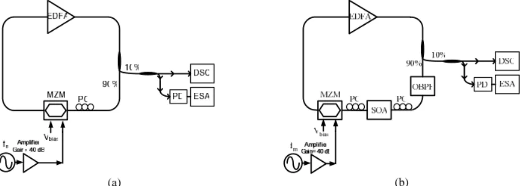
Figure 1(a) illustrates a typical HML-EDFL with an intra-cavity EOM based mode-locker, which consists of an Erbium-doped fiber amplifier (EDFA), a pair of Faraday optical isolators, a polarization controller (PC), a LiNbO3 Mach-Zehnder interferometer based EOM, and an optical coupler (OC) with 10 % output coupling ratio.
(a) (b)
Fig. 1. The schematic diagrams of the (a) EDFL and (b) SOA-and-OBPF-filtered HML-EDFL. PC: polarization controller; OC: optical coupler; EDFA: Erbium-doped fiber amplifier; MZM: Mach-Zehnder intensity modulator; SOA: semiconductor optical amplifier; OBPF: optical bandpass filter.
The EOM DC-biased at its half-wave voltage (Vπ ≅ 8 V) is driven by a microwave synthesizer (Rhode & Schwartz, SML01) with the output power and the SSB phase noise of 22 dBm and -130 dBc/Hz (measured at offset frequency of 100 kHz from carrier), respectively, at frequency of 1 GHz. The PC is properly adjusted to optimize the polarization of the circulating pulses for the EOM, and two Faraday optical isolators ensure the unidirectional propagation of light in the EDFL cavity. As a result, the stable HML-EDFL pulse-train can be obtained when the modulating frequency is detuned to coincide with one harmonic of longitudinal modes in the EDFL cavity. The length of the EDFL ring cavity is 32 m, providing a longitudinal mode spacing of 6.25 MHz. On the other hand, the schematic diagram of an SOA-filtered HML-EDFL is shown in Fig. 1(b). The commercial
fiber-pigtailed SOA exhibits a small-signal gain of 25 dB and a saturated output power of -1.5 dBm when operating at unitary gain (or nearly transparent) condition. In this case, the bias current, operating temperature, 3-dB linewidth and central wavelength of the SOA are set as 57 mA, 24 oC, 30.4 nm, and 1530 nm, respectively. A PC is used to adjust the polarization of light for the SOA. To suppress the supermode noise and SSB phase noise, an OBPF (JDS Uniphase, TB1500B) with 3dB bandwidth 1.38 nm is inserted into the HML-EDFL.
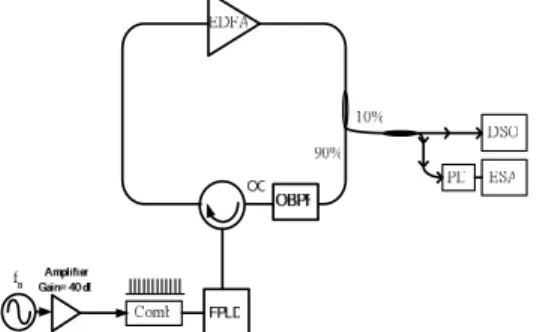
Fig. 2 The schematic diagram of the EDFL mutually injection-mode-locked with a gain-switched FPLD. Comb: Electrical pulse generator; FPLD: Fabry-Perot laser diode.
On the other hand, the FPLD-IML-EDFL is performed by seeding the EDFL with a gain-switched FPLD, as shown in Fig. 2. It consists of a close-loop EDFA with 10 % output coupling ratio, a comb-generator-driven FPLD, an OBPF, and an optical circulator. The wavelength, threshold current, and longitudinal mode spacing of the free-running FPLD operated at 25 oC are about 1550 nm, 8 mA, and 1.2 nm, respectively. A comb generator driven by 27-dBm microwave signal at 1 GHz is employed to provide an electrical pulse-train for gain-switching the FPLD DC-biased at 3.4 mA. The central wavelength of the OBPF is adjusted to match that of the FPLD, which avoids the feedback injection of the amplified spontaneous emission (ASE) of the EDFL into the FPLD. In particular, the gain-switched FPLD pulse amplified by the EDFL is fedback into the FPLD itself, achieving a mutual IML between the FPLD and EDFL link. Such a configuration effectively suppresses the ASE as well as the SSB phase noise of the EDFL. The feedback injection from EDFL is also used to facilitate single longitudinal mode lasing of the FPLD with improved SMSR. Note that the feedback wavelength of the amplified FPLD pulses must coincide with the central longitudinal mode of the FPLD at 1550 nm in order to obtain the lowest SSB phase noise (timing jitter) and the highest SMSR.
The pulsewidth and the output power are monitored using a digital sampling oscilloscope (Agilent, 86100A+86109B), an optical spectrum analyzer with 0.01-nm resolution (Advantest, Q8384), and an optical power meter (ILX Lightwave, OMM-6810B+6727B), respectively. Assuming that the optical pulse-train exhibits small and stationary phase deviations (i.e. small timing jitter) without any secondary phase deviating sidebands, a spectral domain technique is employed to characterize the SSB phase noise and pulse-to-pulse timing jitter characteristics of the EDFL pulses [10, 15-19]. Such a technique neglects the influences of pulse shape and pulsewidth fluctuations, which assumes no correlation between amplitude and phase fluctuations. The SSB phase noise is quantified by measuring the noise spectral power density with an electrical spectrum analyzer (ESA, Agilent HP8565E) at a resolution bandwidth of 1 Hz in connection with a photodetector (New Focus 1014). The timing jitter and the SMSR in a given bandwidth are then calculated and analyzed by using phase-noise-utility software of the RF spectrum. By subtracting the SSB phase noise spectrum at a higher harmonic frequency (for example, the 10th harmonics, n = 10) with that at the fundamental frequency (n = 1) of the EDFL pulses, the rms timing jitter in a bandwidth extending from fL
{
[
(
[
( ) ( )]
) (
)
]
}
2 1 2 10 / 10 / 0 1 / 10 10 2 2 1 ) ( 1∫
− − = H L n f f f L f L df n f f π σ (1)where fL and fH are integration boundaries, L1(f) and Ln(f) are phase noise power spectral
densities of fundamental and nth harmonics signals, respectively. The n denotes the harmonic number and f0 is the repetition frequency of the laser pulse.
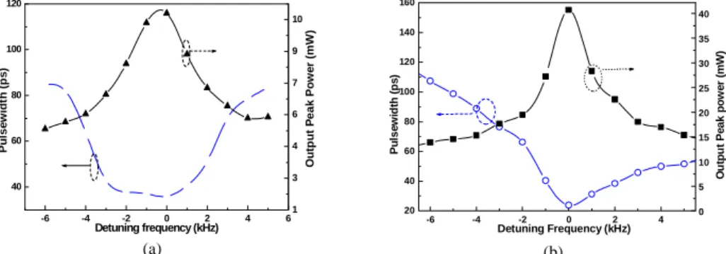
-6 -4 -2 0 2 4 6 40 60 80 100 120 1 3 4 6 7 9 10 P u ls ew id th ( p s) Detuning frequency (kHz) O u tp u t P e a k Po w e r (m W ) (a) -6 -4 -2 0 2 4 20 40 60 80 100 120 140 160 0 5 10 15 20 25 30 35 40 P u ls e w id th (p s ) Detuning Frequency (kHz) O u tpu t P e a k pow e r (m W ) (b)
Fig. 3. The peak power (solid up-triangle) and pulsewidth (solid square) as a function of detuning frequency for (a) the HML-EDFL and (b) the FPLD-IML-EDFL systems.
3. Results and discussion
3.1 The HML-EDFL and the FPLD-IML-EDFL
The optimized HML-EDFL pulse is determined from the evolution of pulse shape, especially the observation on the maximum peak power and the shortest pulsewidth versus detuning frequency, as shown in Fig. 3(a). It is clearly observed that the peak power is attenuated and the pulse is broadened as the modulating frequency detuned. The 3-dB detuning bandwidth (defined as the difference between the optimized mode-locking frequency and the frequency corresponding to the doubling in pulsewidth) of the HML-EDFL is only 7 kHz. The shortest pulsewidth of 36 ps and the maximum output peak power of 12.3 mW of the HML-EDFL are obtained, as shown in Fig. 3(a).
200 400 600 800 0 2 4 6 8 10 12 -10 -5 0 5 10 -120 -100 -80 -60 -40 2 4 6 8 10 12 -120 -100 -80 -60 -40 Time (ps) (4) Frequency (MHz) (3) Po wer (mW ) (2) Po w e r (d B m ) (1) (a) -10 -8 -6 -4 -2 0 2 4 6 8 10 -120 -80 -40 Po w e r ( d B m ) Frequency (kHz) -120 -80 -40 -120 -80 -40 (3) (2) (1) (b)
Fig. 4. (a) Supermode noise spectrum (left) and pulse shape (right) of the HML-EDFL (upper part) and the HML-EDFL with intra-cavity SOA and OBPF (lower part). (b) The supermode noise spectra measured at resolution bandwidth of (1) 1 Hz; (2) 10 Hz; and (3) 100 kHz.
The supermode noise results from the beating between longitudinal modes and ASE of the HML-EDFL, which inevitably causes large intensity fluctuations in the HML-EDFL pulse-train. Typically, the HML-EDFL exhibits a relatively small SMSR of 45 dB (see Fig. 4), owing to the extremely long upper-level lifetime of excited erbium ions in EDFL (~10 ms) and the relatively low mode-beating frequencies of the HML-EDFL with a long cavity length. Note that the SMSR measurement was carefully performed in our experiments, since which is dependent on the background noise of the electrical spectrum analyzer under an extremely low supermode noise condition. For example, the measured SMSR could be distorted when
the electrical spectrum analyzer is set at larger resolution bandwidth (RBW), as shown in Fig. 4 (b). By reducing the RBW from 100 kHz to 1 Hz, the SMSR is enlarged from 45 dB to 90 dB as the background noise of the spectrum analyzer decreases from -85 dBm to -126 dBm. As a result, the SMSR can only be precisely obtained by setting the smallest RBW of the electrical spectrum analyzer. In conventional HML-EDFL, the SSB phase noises and timing jitter at offset frequency of 100 kHz are -114 dBc/Hz and 0.6 ps, respectively,as shown in Fig. 7. The low-frequency spurs at 20 Hz, 55 Hz, and 60 Hz are mainly due to the fans, ambient vibrations, wall current, and their harmonics, respectively [21].
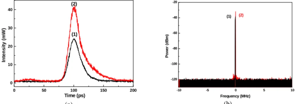
0 50 100 150 200 0 10 20 30 40 (1) (2) In te n s it y ( m W ) Time (ps) (a) -10 -5 0 5 10 -120 -100 -80 -60 -40 -20 Po we r ( d B m ) Frequency (MHz) (1) (2) (b)
Fig. 5. (a) The pulse shapes and (b) the supermode noise spectrum (RBW = 1 Hz) of (1) the free-running FPLD, and (2) the FPLD-IML-EDFL.
In a FPLD-IML-EDFL, the gain-switched FPLD pulse experiences a resonant amplification process in the EDFL, and reaches its highest peak power and shortest pulsewidth as the modulating frequency of the FPLD coincides with the harmonic frequency of the longitudinal mode in EDFL. The output power and the pulsewidth of the FPLD-IML-EDFL versus the frequency detuning are shown in Fig. 3(b). The optimized pulse and the peak power of 22 ps and 40.7 mW, respectively, are shown in Fig. 5(a). When the repetition frequency detunes, the pulses circulated in the EDFL arrives the gain medium with a slight temporal deviation, which eventually leads to a broadened pulse shape contributed by the superposition of circulated pulses. A multiple pulse splitting effect happens as the frequency detuned beyond a bandwidth of 17.8 kHz, as shown in Fig. 3(b).
10 100 1k 10k 100k 1M 10M -130 -120 -110 -100 -90 -80 -70 -60 S S B P h ase N o ise ( d B c/H z ) Offset Frequency (Hz) (1) (2) (a) 10 100 1k 10k 100k 1M 10M 0.01 0.1 1 Offset Frequency (Hz) Timing J itte r (p s ) (1) (2) (b)
Fig. 6. (a) The SSB phase noise spectra and (b) the timing jitter of (1) the free-running FPLD and (2) the FPLD-IML-EDFL.
The SSB phase noise and the corresponding timing jitter of a freerunning FPLD pulse are -114 dBc/Hz at 100 kHz offset frequency and 0.32 ps between a frequency interval of 10 Hz and 100 kHz, respectively, as illustrated in Fig. 6. In comparison, the FPLD-IML-EDFL has lower phase noise of -121 dBc/Hz and timing jitter of 0.25 ps than those of a free-running FPLD due to the mutually IML configuration (see Fig. 6). The spontaneous emission noise of the FPLD can be greatly reduced under such a FPLD-IML-EDFL link, and the energies of adjacent pulses are equalized due to the intensity-dependent gain of the FPLD [8]. Such a
FPLD based filtering effect is attributed to its relatively fast carrier recovery rate (from 0.5 to 1 ns) and gain saturation effect, providing the enhancement on SMSR from 87 to 91 dB, as shown in Fig. 5(b). In comparison, the SMSR, SSB phase noise, and timing jitter of the FPLD-IML-EDFL are far better than those of the HML-EDFL.
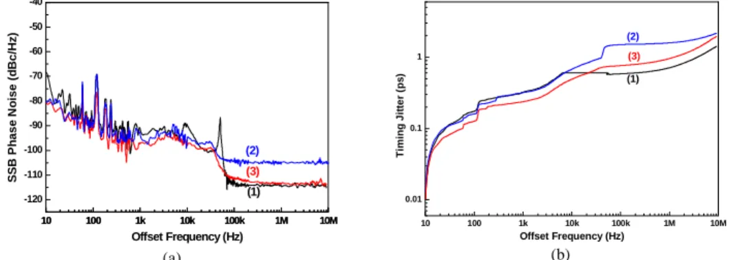
10 100 1k 10k 100k 1M 10M -120 -110 -100 -90 -80 -70 -60 -50 -40 10 100 1k 10k 100k 1M 10M (3) (2) S S B P h ase N o ise (d B c/H z ) Offset Frequency (Hz) (1) (a) 10 100 1k 10k 100k 1M 10M 0.01 0.1 1 (1) (3) Ti m ing J it te r (ps ) Offset Frequency (Hz) (2) (b)
Fig. 7 (a) The SSB phase noise in HML-EDFL (1) without SOA, (2) with SOA and (3) with SOA and OBPF; (b) the timing jitter in HML-EDFL (1) without SOA, (2) with SOA and (3) with SOA and OBPF.
3.2 The HML-EDFL with SOA
Due to a relatively fast carrier recovery rate and gain saturation effect of the SOA [22, 23], some SOA based high-pass filtering schemes proposed for suppressing low-frequency noise in EDFL have previously been demonstrated by Xu et al. and Yao et al. [22, 24]. Theoretically, the supermode noise beating effect can be quantitatively discussed by defining the gain (R) of output power fluctuation to that of input power fluctuation (defined as ΔP/P within a frequency interval Δν) in a laser. This can be derived from the rate equation of the small-signal gain under a perturbation on average power [24, 25]. With a simplified gain fluctuation of g = g0+Δg, Peng et al. [25] described the equation as
1
(
0 1)
0 − Δ − = ⎟⎟ ⎠ ⎞ ⎜⎜ ⎝ ⎛ + ⋅ Δ + Δ g sat in sat g in c e E P E e p g dt g d τ , (2)where Pin denotes the average power of the stable mode-locked pulses, ΔPin denotes the power
fluctuation due to the beating between the supermodes, Esat is the saturated energy of gain
medium, and τc is the carrier lifetime. Yao et al. [24] have concluded the analytical
expression of R by solving Eq. (2)
2 2 2 ' 2 2 2 ' ' 1 ) 1 ( 1 1 ) 1 ( 1 0 0 0 ⎥ ⎥ ⎥ ⎥ ⎥ ⎦ ⎤ ⎢ ⎢ ⎢ ⎢ ⎢ ⎣ ⎡ Δ + ⎥ ⎦ ⎤ ⎢ ⎣ ⎡ Δ × × − + ⎥ ⎥ ⎥ ⎥ ⎥ ⎦ ⎤ ⎢ ⎢ ⎢ ⎢ ⎢ ⎣ ⎡ Δ + ⎥ ⎦ ⎤ ⎢ ⎣ ⎡ × × − − = Δ Δ = − − ω τ ω ω τ τ c at s avg g g c c sat avg g g in in out out E P e e E P e e P P P P R , (3)
where τc’ = [τc-1 + egPavg/Esat]-1 denotes the effective carrier lifetime, and Pavg is the average
power of the laser. The first term in the square root describes the power fluctuation of the EDFA or SOA, while the second term denotes the supermode beating fluctuation by longitudinal modes. Typically, the small mode-spacing of conventional EDFL (Δν < 10 MHz) causes a numerous cavity modes within the mode-locking spectrum (with 3-dB bandwidth >100 GHz), which beats each other in the EDFL cavity to produce supermodes. The R of EDFA approaches 1 since τc ≥ 10 ms and Δν << (2πτc)-1, which indicates a large power
fluctuation and a strong supermode beating are usually involved in the output HML-EDFL pulses. Such a supermode-noise-induced power fluctuation can be solved with an intra-cavity SOA in deeply saturating condition (Pineg0τc/Esat >> 1). The ultrashort τc of SOA (≤1 ns)
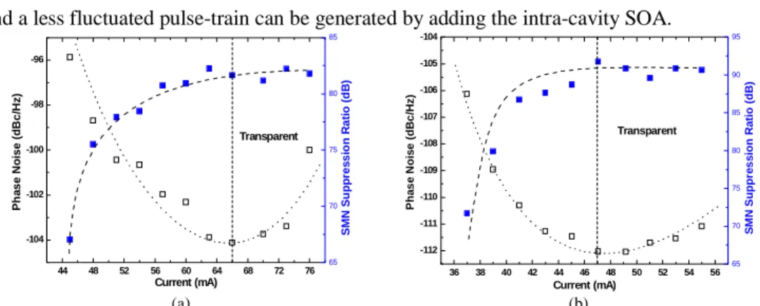
and a less fluctuated pulse-train can be generated by adding the intra-cavity SOA. 44 48 52 56 60 64 68 72 76 -104 -102 -100 -98 -96 Transparent Current (mA) P h as e N o is e ( d B c /H z ) 65 70 75 80 85 SMN Su p p re s s io n R a ti o (d B ) (a) 36 38 40 42 44 46 48 50 52 54 56 -112 -111 -110 -109 -108 -107 -106 -105 -104 Current (mA) P h as e N o is e ( d Bc /H z ) Transparent 65 70 75 80 85 90 95 S M N S uppr e s s ion R a ti o ( dB ) (b)
Fig. 8. The SMSR and the SSB phase noise of (a) the HML-EDFL with SOA and (b) the HML-EDFL with SOA and OBPF at different SOA currents.
By taking the advantage of the SOA based high-pass filtering effect, the SMSR performance of a HML-EDFL with an intra-cavity SOA is characterized. The supermode noise located in low-frequency region can thus be suppressed by adding an SOA [23], while the SMSR is significantly improved from 45 dB to 62.4 dB even the SOA is operated at below threshold (absorption) condition. However, the SSB phase noise of the EDFL are degraded from -114 dBc/Hz to -96 dBc/Hz. As the SOA is changed from absorption to unitary gain regime, the SMSR of the HML-EDFL can further be improved to 82 dB or larger. The minimum SSB phase noise and the minimum timing jitter of -104.2 dBc/Hz and 1.4 ps, respectively, can be obtained by driving the SOA at nearly transparent current (~66 mA), as shown in Fig. 8(a). The optimized driving current of the SOA based high-pass filter at its transparent condition is clearly interpreted, while the SMSR can be greatly improved by 40 dB as compared to that of the same HML-EDFL without SOA. Nonetheless, the nearly transparent SOA still causes the EDFL pulsewidth broadening from 36 ps (without the SOA) to 61 ps (with the SOA) and leads to degradation on the SSB phase noise by 10 dB (as compared to the HML-EDFL without SOA). It is evident that the SMSR almost saturates (due to the output power saturation) but the SSB phase noise increases rapidly at higher gain condition of the SOA, which results in the distorted and fluctuated HML-EDFL pulses. In principle, the total noise power of an SOA is contributed by signal-spontaneous beating noise, spontaneous-spontaneous beating noise, amplified signal shot noise, and spontaneous emission shot noise [26-28]. The noise in the SOA is dominated by the spontaneous-spontaneous beating noise when the input signal level is extremely small. When the SOA is operated at larger gain region with higher input signal levels, the signal-spontaneous beating noise and the spontaneous-spontaneous beating noise become more pronounced than other noise terms.
3.3 The HML-EDFL with SOA and OBPF
The SSB phase noise of a HML-EDFL with an intra-cavity SOA filter is strongly correlated with the stimulated or spontaneous emission induced carrier density fluctuation [26, 29, 30]. The spontaneous-emission-induced SSB phase noise is written as Sφ1(f) = hν(G-1)nsp/GPin,
where h is Planck’s constant, ν is optical frequency, G is amplifier gain, nsp is the spontaneous
emission factor, and Pin is input optical power. The stimulated-emission-induced indirect SSB
phase noise is described as Sφ2(f) = [(2πKΓ/λA)24G(G-1)nspτc2Pin]/hν[(2πfτc)2+1] with K =
Δnr(z, t)/Δne(z, t), where Δnr is real refractive index change, Δne is fluctuation of carrier
density, Γ is optical confinement factor, λ is wavelength, A is amplifier cross section, and τe is
carrier lifetime. The theoretical simulation of Stotal(f)=Sφ1(f)+Sφ2(f) interprets that the
minimum phase-noise operation of an SOA can be achieved by setting its driving condition in the unitary gain (or transparent) regime, as depicted in Fig. 9.
0.5 1.0 1.5 -112 -110 -108 -106 -104 -102 -100 -98 -96 -94 S S B P h as e N o ise ( d B c/H z ) Gain of SOA
Fig. 9. The simulated (solid line) and measured SSB phase noises as a function of the SOA gain for the SOA-filtered EDFL without (solid square) and with OBPF (up triangle).
The spontaneous emission dominates the phase noise of the EDFL-SOA link as the SOA operates at under transparent gain condition, whereas the SSB phase noise is mainly contributed by the stimulated emission of the SOA operated at over transparent region. Note that the signal-spontaneous beating noise is inevitable, however, the spontaneous-spontaneous beating noise, which arises from the beating of the ASE components themselves over a wide gain spectrum, can be reduced by loading a narrow-band OBPF matched to the signal frequency. Without an OBPF or an etalon filter, the reduction of signal-spontaneous beating noise is inevitable for SOA operated at gain regime. Subsequently, the pulsewidth broadening and SSB phase-noise degradation problems are concurrently solved by adding an intra-cavity OBPF and operating the SOA at unitary gain regime. These improve the SSB phase noise performance from -104.2 to -112 dBc/Hz and enhance the SMSR from 86 to 90 dB by suppressing the ASE in the HML-EDFL, as shown in Fig. 8(b). In addition, such a configuration also leads to a shortened pulsewidth and a reduced timing jitter of 42 ps and 0.7 ps, respectively, as shown in Figs. 4 and 7(b). Time-domain analyses shown in Fig. 4 have revealed that the insertion of the SOA and the OBPF greatly suppresses the intensity fluctuations. The SMSR of 90 dB in HML-EDFL with SOA and OBPF is far better than that of 45 dB in a typical HML-EDFL. The parametric comparisons on different EDFL systems are summarized in Table 1.
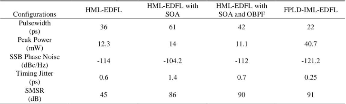
Table 1. Comparisons on performances of versatile EDFL systems
Configurations HML-EDFL
HML-EDFL with SOA
HML-EDFL with
SOA and OBPF FPLD-IML-EDFL
Pulsewidth (ps) 36 61 42 22 Peak Power (mW) 12.3 14 11.1 40.7 SSB Phase Noise (dBc/Hz) -114 -104.2 -112 -121.2 Timing Jitter (ps) 0.6 1.4 0.7 0.25 SMSR (dB) 45 86 90 91
In comparison, the SMSR of the HML-EDFL with intra-cavity SOA and OBPF is better than those systems using only OBPF [31-33] by 10 dB and is equivalent to that of a FPLD-IML-EDFL system. The minimum SSB phase noise of the SOA-and-OBPF-filtered HML-EDFL found at the transparent current condition of the SOA is comparable with that of conventional HML-EDFL. By adding both SOA and OBPF, the reduction in supermode noise and spontaneous-beating-induced SSB phase noise in a HML-EDFL has been confirmed. 4. Conclusions
mode-locked Erbium-doped fiber laser (HML-EDFL) by adding intra-cavity semiconductor optical amplifier (SOA) and optical band-pass filter (OBPF). A typical HML-EDFL system exhibits the SSB phase noise, corresponding timing jitter, and supermode noise suppressing ratio (SMSR) of -114 dBc/Hz (at 100 kHz offset frequency), 0.6 ps (integrating from 10 Hz to 100 kHz), and 45 dB, respectively. In comparison, a gain-switched Fabry-Perot laser diode (FPLD) mutually injection-mode-locked EDFL (FPLD-IML-EDFL) exhibits the start-of-the-art performances, such as the SMSR, the SSB phase noise and timing jitter of 91dB, -121.2 dBc/Hz, and 0.25 ps, respectively. The extremely high SMSR is due to the relatively fast carrier recovery rate and the gain saturation effect of the mutual injection-locked FPLD, which acts as a supermode noise suppressor. With an intra-cavity SOA based high-pass filter driven at unitary gain condition, we primarily demonstrate that the SMSR of the HML-EDFL increased to 86 dB becomes comparable with that of the FPLD-IML-EDFL, however, at the cost of degrading SSB phase noise (-104.2 dBc/Hz) and increasing timing jitter (1.4 ps). Theoretical and experimental results conclude that the optimized driving current of the SOA based high-pass filter for the EDFL is at transparent current, while the SSB phase noise is suppressed without sacrificing the SMSR of the EDFL. The SMSR saturates at higher driving current of SOA, whereas the pulsewidth, SSB phase noise and timing jitter of the HML-EDFL seriously degrade. By adding an OBPF into the cavity of the HML-EDFL with SOA, the SMSR and SSB phase noise can further be improved to 90 dB and -112 dBc/Hz, respectively. The pulsewidth and the timing jitter of the HML-EDFL with both SOA and OBPF are reduced to 42 ps and 0.7 ps, respectively. The OBPF maintains the SMSR performance of the HML-EDFL with SOA without sacrificing its pulsewidth, SSB phase noise and timing jitter performances. Such a high SMSR response has already been comparable with that of a state-of-the-art FPLD-IML-EDFL system.
Acknowledgments
This work was supported in part by the National Science Council (NSC) of the Republic of China under grants NSC93-2215-E-009-007 and NSC94-2215-E-009-040.