國
立
交
通
大
學
資訊科學系
碩
士
論
文
遠 端 直 接 記 憶 體 存 取 機 制 的 系 統 的 實 作
An Implementation of Remote Direct Memory Access
研 究 生:蔡嘉泰
遠端直接記憶體存取機制的系統的實作
An Implementation of Remote Direct Memory Access
研 究 生:蔡嘉泰 Student:Chia-Tai Tsai
指導教授:簡榮宏 Advisor:Rong-Hong Jan
國 立 交 通 大 學
資 訊 科 學 系
碩 士 論 文
A ThesisSubmitted to Institute of Computer and Information Science College of Electrical Engineering and Computer Science
National Chiao Tung University in partial Fulfillment of the Requirements
for the Degree of Master
in
Computer and Information Science
June 2004
Hsinchu, Taiwan, Republic of China
遠端直接記憶體存取機制的系統的
實作
研究生:蔡 嘉 泰 指導教授:簡榮宏博士
國立交通大學資訊科學研究所
摘 要
近幾年來,隨著網路的發展,網路頻寬已經從 10M bps 成長到 100M bps, 現在已經有 10G bps 網路環境。影響網路頻寬的因素,已由網路硬體,移到網路 協定軟體. 在傳統的架構之下,當封包在不同協定層中傳遞時,會發生許多次的 資料複製,有許多增進效能的研究,致力於改善資料複製的問題。在本篇論文中, 我們將實做一個新提出的遠端直接記憶體存取 (Remote Direct Memory Access ㄝ RDMA)網路協定,RDMA 這是一個能夠將資料直接搬移到指定的記憶體位址的網 路協定,來達到減少資料複製的發生。結果顯示利用 RDMA 方法在傳遞封包大小 較大的封包時,能夠很有效的增加傳輸頻寬. 我們發現 RDMA 協定適用在傳遞封 包較大的環境下,效能將會有相當大的增益。An Implementation of Remote Direct
Memory Access
Student:Chia-Tai
Tsai
Advisor:Dr. Rong-Hong Jan
D
EPARTMENT OF
C
OMPUTER AND
I
NFORMATION
S
CIENCE
N
ATIONAL
C
HIAO
T
UNG
U
NIVERSITY
Abstract
With the increase of network bandwidth from 10M to 10G bps, the factors that affect network system performance have found to be relevant with Network Protocol. In traditional architecture, the packets are copied among different protocol layers, before they are transmitted. The data copy consumes many recourses and leads to system inefficiency. However, few studies concern about increasing system efficiency from this point of view. In this thesis, we implement a new Network Protocol, called as Remote Direct Memory Access (RDMA), which can move data packets to a specific memory address. Therefore, the system performance can be improved. Numerical results show that RDMA can achieve a better performance if the packet size is large.
Acknowledgements
Special thanks goes to my advisor Dr. Rong-Hong Jan for his guidance and enduring support in the whole process of this thesis. Thanks also to all persons in Computer Network Laboratory for their advice and support during these two years.
Finally and most importantly, I wish to thank my family for putting up with me and supporting me during the ups and downs of writing this thesis.
Contents
1 Introduction 6
2 Related Works 8
2.1 Zero Copy . . . 8
2.1.1 Structure of Zero Copy . . . 9
2.1.2 Zero Copy Scheme [8] . . . 10
2.2 MPA Protocol . . . 12 2.3 DDP Protocol . . . 15 2.4 RDMA Protocol . . . 17 3 System Architectures 19 3.1 Overview . . . 19 3.2 uC/OS-II . . . 20 3.2.1 Features [9] . . . 20 3.2.2 Modification . . . 22 3.3 lwIP . . . 26 3.3.1 Overview . . . 26 3.3.2 lwIP API . . . 26 3.4 RDMA Protocol . . . 36
3.4.1 RDMA Operation . . . 36
3.4.2 The flow chart of RDMA . . . 40
3.4.3 RDMA and DDP API . . . 41
4 Implementation and evaluation 45
4.1 Experimental environment . . . 45 4.2 Evaluation and result . . . 47
List of Figures
2.1 Process of Data Copy. . . 9
2.2 Time reduction of data copy by using shared memory. . . 10
2.3 OS illustration of user-kernel shared memory. . . 12
2.4 DDP, MPA, and TCP layering. . . 13
2.5 MPA Framing process. . . 13
2.6 FPDU with Marker. . . 14
2.7 re-segment with Marker. . . 14
2.8 Tagged Message Model. . . 16
2.9 Untagged Message Model. . . 17
2.10 RDMA Operations. . . 18
3.1 Task State. . . 21
3.2 Process of executing the task with the highest priority. . . 22
3.3 Multi-tasking. . . 23
3.4 DATA TYPES. . . 24
3.5 Interruption and Content Switch. . . 25
3.6 Initialized stack of a task. . . 26
3.7 Initialized source code. . . 27
3.9 Transformation process of Berkeley socket API. . . 28
3.10 Communication between Application and TCP/IP protocol. . . 29
3.11 API type 1. . . 29 3.12 netconn bind. . . 30 3.13 netconn listen. . . 30 3.14 netconn close. . . 30 3.15 API type 2. . . 31 3.16 netconn connect. . . 32 3.17 API type 3. . . 32 3.18 netconn send. . . 33 3.19 netconn write. . . 33 3.20 API type 4. . . 34 3.21 netconn accept. . . 35 3.22 netconn recv. . . 36
3.23 The procedure of server. . . 37
3.24 The procedure of client. . . 38
3.25 RDMA Write Operation. . . 39
3.26 RDMA Read Operation. . . 39
3.27 Flow chart of RDMA Write. . . 40
3.28 Flow chart of RDMA Read. . . 41
3.29 Protocol Layering. . . 42
4.1 Experimental environment. . . 46
4.2 Ticks taken in transmitting different packet sizes in TCP/IP. . . . 47 4.3 Ticks taken in transmitting different packet sizes in RDMA protocol. 48
4.4 Result of transmitting 1,400KB data packet in TCP/IP and RDMA
protocol. . . 49
4.5 Result of transmitting 500KB data packet in TCP/IP and RDMA
protocol. . . 50
4.6 Result of transmitting 50KB data packet in TCP/IP and RDMA
protocol. . . 51
Chapter 1
Introduction
With the development of network bandwidth, the bandwidth has increased from 10M bps to 100M bps in these years. Up to now, the bandwidth could reach 10G bps in network hardware. However, studies have pointed out that the main factor having bandwidth of data source between data sink is no longer from the network hardware. By this point of view, I would address this issue from network protocol perspective. When the data source transfers data packets, data sink would consume the greatest resource in data copying because when processing data packets, the system would copy a temporary data in each network protocol layer. This process would reduce system efficiency and waste system sources, which both lead to transfer inefficiency. The transfer efficiency can improved by implementing the following ideas: (1) copy-avoidance [1] [2] and (2) Marker PDU Aligned (MPA) [3] and Direct Data Placement (DDP) [4].
In Linux, for instance, to increase system efficiency, zero copy [1] [2] is taken to avoid data copy in transferring data packets. Many studies have pointed out that by doing so, system efficiency could increase extra forty to eighty percent [5], compared with those with data copy processes. Therefore, in this light, to avoid sources consuming process caused by data copying, copy avoidance might be a
solution.
The second approach, is to apply MPA and DDP protocol to process data packets. This approach can increase network bandwidth and reduce the time in processing data packets. Consider that a network used TCP as its transport protocol. If some data packets lose in transmitting process, TCP will re-transmit data packets and reassemble data packets in order. If we use MPA Protocol, even though the data packets are out of order, the data packets will be quickly transmit to Upper Layer Protocol (ULP). Then, DDP Protocol will directly move the content of data packets to assigned memory address. Therefore, by combining these two processes, system efficiency can be increased.
In this thesis, we investigate the following problems: (1)what are possible so-lutions for increasing network bandwidth? (2)Does copy avoidance, which reduced data copy, increase system efficiency? (3)Does the combination of MPA and DDP reduce the time in transferring network packets?
This thesis is organized into five chapters. The first chapter is to introduce basic background for understanding the relevant concepts; Chapter 2 to introduces concepts about Copy Avoidance, DDP Protocol, and MPA Protocol; Chapter 3 introduces uC/OS-II, lwIP [6] and RDMA [7]; The implementation and its evalua-tion are given in Chapter 4; finally, Chapter 5 gives conclusion and possible future thesis.
Chapter 2
Related Works
To provide a background for understanding how this thesis constructed, a re-view of relevant works about Zero copy, DDP Protocol, MPA Protocol and RDMA Protocol is given in this chapter.
2.1
Zero Copy
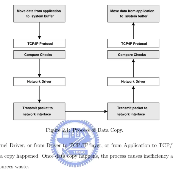
The overhead, produced in processing data copy and checksum, was the main cause for bandwidth reduction and system inefficiency. Some studies have shown that the f Zero copy can reduce the number of times in copying data. In general, Data copy would happen once in single-copy process when the application requests to read data from transport layer. Statistically, single-copy process would reduce 60% overhead in this process. However, Zero-Copy is the shared memory mixed with application or kernel or NIC interface. When the application is going to transmit data, all it needs to do is to store the data in shared memory. Therefore, the system could retrieve the data from it without the process of data copy. System efficiency would increase greatly. Figure 2.1 shows data copy occurs in transmitting data in a network.
Move data from application to system buffer TCP/IP Protocol Compare Checks Transmit packet to network interface Network Driver
Move data from application to system buffer TCP/IP Protocol Compare Checks Transmit packet to network interface Network Driver
Figure 2.1: Process of Data Copy.
Kernel Driver, or from Driver to TCP/IP layer, or from Application to TCP/IP, data copy happened. Once data copy happens, the process causes inefficiency and resources waste.
2.1.1
Structure of Zero Copy
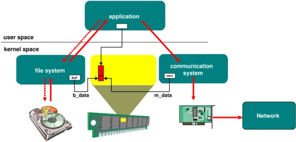
To increase system efficiency, the number of times of data copy should be reduced. This reduction could be done by shared memory. As we see from Fig-ure 2.2, instead of copying the data, all involved processes will refer to the same memory address in transmitting information. Thus, the number of data copy is reduced.
file system communicationsystem application
file system communicationsystem
application user space kernel space buf Network mbuf b_data m_data
Figure 2.2: Time reduction of data copy by using shared memory.
2.1.2
Zero Copy Scheme [8]
In [8], it present four methods to implement the Zero Copy scheme as follow. 1. User accessible interface memory
When we use user accessible interface memory, user or kernel should be able to access to the memory in NIC interface. User or kernel must readdress the memory space in order to be later used. Some requirements are necessary.
(a) This method has to have hardware support and modified software. (b) In sink node, network hardware must know about which process that the
data packets belong to. This is for correctly transmit the data packets to memory address it belongs to.
(c) Because we readdress memory space, other memory managements to manage the memory space must be taken.
(d) Due to the limited memory space in NIC interface, it is possible to encounter problems about inadequate resource in running.
2. Kernel-network shared memory
(a) It refers to OS kernel management of memory space of NIC interface Also, it refers to utilize DMA or PIO(Program I/O) to move data from Application buffer to NIC interface.
(b) Application does not need to change software if we take the method suggested above.
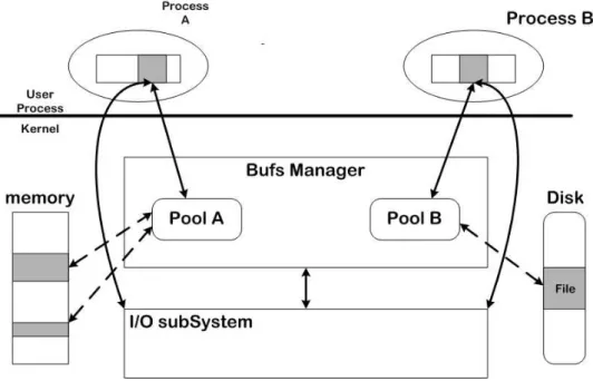
(c) As for OS kernel, due to the limited memory space in NIC interface, we should be particularly careful with the memory space management. 3. User-kernel shared memory (see Figure 2.3)
(a) Some new APIs are created between user and kernel in order to read-dress memory space.
(b) To utilize DMA to move information between shared memory and NIC. (c) The NIC hardware must be able to receive the incoming data, which
will be move to the correct memory address by DMA. 4. User-kernel page remapping + COW (copy-on-write)
(a) The system will modify the content of system MMU (Memory Man-agement Unit) in order to remap the buffer page. This modification is needed for two reasons: when we have to quickly switch the memory space and transmit data without data copy.
(b) After doing so, socket and VM system do not need to make any modi-fication.
Figure 2.3: OS illustration of user-kernel shared memory.
(c) Every buffer differs in size, which is required to be the same with page size. In other words, the size of the buffer corresponds to a page. (d) Application must avoid reusing the same buffer too quickly.
Based on the above ideas, data copy times could be decreased to increase system efficiency. Therefore, the goal of creating a wider bandwidth could be reached.
2.2
MPA Protocol
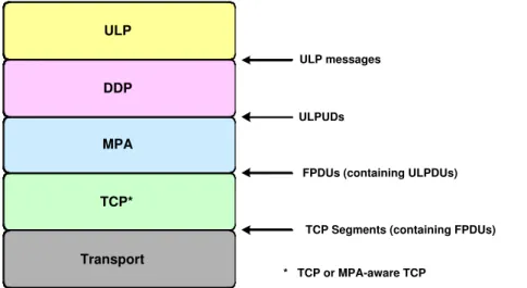
MPA, an extra layer out of protocol, exists above TCP and under DDP. The layer of protocol is ahown in Figure 2.4. The main feature of MPA is pointing out how many octets between Marker and Framing Protocol Data Unit (FPDU).
In transmitting information in TCP, byte streaming is always the only way. Yet, packets could be simply received one by one without being able to know where
ULP DDP MPA TCP* Transport ULP messages ULPUDs
FPDUs (containing ULPDUs)
TCP Segments (containing FPDUs)
* TCP or MPA-aware TCP
Figure 2.4: DDP, MPA, and TCP layering.
the FPDU is in byte streaming. Its position in byte streaming must be known by reassembling the packets through TCP Protocol. Subsequently, DDP could get the information after FPDU reassemble.
Marker is defined for the purpose of implementing MPA Protocol. In the process of transmitting PDU to MPA layer by DDP, MPA needs to add marker in received PDU between each 512 octet interval. As long as sink node receives seg-ment, it would define the position stored in FPDU on the basis of the information that marker has stored, as Figure 2.5 shows.
ULP Message
ULPDU ULPDU ULPDU
DDP DDP DDP
FPDU M
C R C
MPA MPA FPDU
C R C MPA FPDU C R C M M
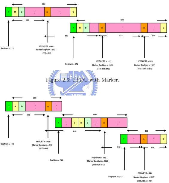
With a support of TCP to MPA, as long as TCP receives segment in MPA format, it would quickly transmit FPDUs to MPA. MPA would recognize which FPDU the received information belongs to from the Marker. Even though the packet would pass through the re-segment, the recognition would still succeed as shown in Figure 2.6 and 2.7.
T M D .. . m .. . C T M D .. . m .. . m .. . C SeqNum = 113 400 512 SeqNum = 913 800 800 FPDUPTR = 112 Marker SeqNum = 1025 (113+400+512) FPDUPTR = 624 Marker SeqNum = 1537 (113+400+512*2) 512 176 FPDUPTR = 400 Marker SeqNum = 513 (113+400)
Figure 2.6: FPDU with Marker.
T M D .. . m .. . T .. . C M D .. . m .. . T .. . m .. . C SeqNum = 113 400 600 FPDUPTR = 400 Marker SeqNum = 513 (113+400) 600 400 176 SeqNum = 713 SeqNum = 1313 512 512 FPDUPTR = 112 Marker SeqNum = 1025 (113+400+512) FPDUPTR = 624 Marker SeqNum = 1537 (113+400+512*2)
Therefore, as we see, MPA Protocol provides framing mechanism in TCP for DDP. Utilizing the mechanism provided by MPA, we could know what FPDU every received packet belongs to in byte streaming process. In this way, the re-ceived content in every packet could be quickly transmitted to DDP. Finally, DDP would write in the correct memory address without waiting for TCP reassembles or retransmits. Therefore, transmit time could be reduced and bandwidth would sequentially increase.
2.3
DDP Protocol
DDP takes care of moving the information to a designated memory ad-dress without system processing. Therefore, DDP would increase system efficiency. To understand how DDP works, a brief introduction is fiven in the following:
DDP refers to a mechanism placing information to a correct memory address without involve ULP process. A STag, a signal defined as to represent memory ad-dress in DDP Protocol, would communicate and register between sink and source nodes before transmitting information. Therefore, when data packets are trans-mitted, the STag would be included in data packets. DDP Protocol defines a STag used for signaling a memory address. Before transmitting data, sink node will register a STag to source node after their communication between each other. As long as the data is transmitting, STag will be embedded in data packet. When source node starts to transmit data, it would segment the message first and embed the STag in a data packet. Then the data packet would be transmitted to sink node as a result. When the data packet is arrived at sink node, sink node is able to get a STag. Sink node will know what the memory address is according to the
move the data to the correct memory address by DDP Protocol. In general, DDP supports two transmit the following models: 1. Tagged Buffer data transfer model see Figure 2.8:
As ULP registers a memory address for source node to use, DDP would give ULP a the-only-one code name, called STag, to mark the memory address for the received information.
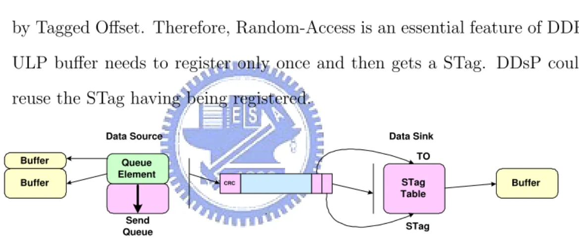
In the process of transmitting information from source node to sink node by utilizing STag and Tagged Offset, the correct buffer could be found by STag. Then the correct address of received information in buffer could be known by Tagged Offset. Therefore, Random-Access is an essential feature of DDP. ULP buffer needs to register only once and then gets a STag. DDsP could reuse the STag having being registered.
Queue Element Buffer Buffer CRC STag Table Buffer Send Queue TO STag Data Source Data Sink
Figure 2.8: Tagged Message Model.
2. Untagged Buffer data transfer model see Figure 2.9:
Information of this sort can be transferred directly without ULP registration. The sink node has to manage buffers for Untagged Message storage. When there is an Untagged Message arriving at sink node, one buffer is required to receive one untagged. A buffer could not be used for storing another Untagged Message unless the buffer has been declared deleted.
and source node to communicate with control message or error message. Queue Element Buffer Buffer CRC Send Queue
Data Source Data Sink Queue Element Recv Queue Buffer Buffer MO QN, MSN
Figure 2.9: Untagged Message Model.
2.4
RDMA Protocol
Based on the functions provided by DDP, RDMA contributes to nearly com-plete Protocol functions. Instead of having simply one-way function of Write of DDP, RDMA, utilizes features of Untagged and Tagged Message, has achieved two-way transmit function. Details of features of RDMA Protocol are illustrated as follows.
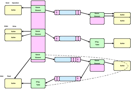
RDMA improves disadvantages of DDP, such as improving one-way transmit to two-way transmit. Types of operations provided by RDMA would be discussed below and illustrated in Figure 2.10:
1. Send Operation Type
Source node will directly transmit an untagged message to sink node. Before this transmitting data, there is no need registering a STag between these two node
2. RDMA Write
before transferring data. RDMA write process is identical with the process of how system deals with DDP Tagged message.
3. RDMA Read
Sink node will register a STag. This STag will be accompanied with the re-quest of send operation and subsequently sent to source node. When source node receives the request, it would write the data into memory address the STag represents in sink node. This is done by utilizing RDMA write oper-ation. Therefore, UDMA read is an operation built by Send Operation and RDMA Write Operation.
Buffer Buffer Buffer C R C C R C C R C Queue Element Queue Element Queue Element Queue Element STag Table Queue Element C R C STag Table Buffer Buffer Buffer Buffer Buffer Send Operation RDMA Write RDMA Read
Chapter 3
System Architectures
In this chapter, we will show how RDMA system works, and elements com-posing of the whole RDMA system architecture, such as OS, the portability of TCP/IP RDMA Protocol in details.
3.1
Overview
Our prototype of RDMA system is created on a development platform, which is the core of MIPS and has 16 MB ROM to be used. Also, on the platform, there is an Ethernet, which could be used to transmit data packets.
In addition, we port uC/OS-II to the platform having been mentioned ear-lier. uC/OS-II has multitasking and priority mechanism, which both altogether contribute to execute the task with higher priority. We create our RDMA system on the basis of these features of uC/OS-II. However, uC/OS-II does not support TCP/IP protocol, light weight IP (lwIP) is selected and ported to uC/OS-II.
Our analysis of the increased system efficiency would base on the result of implementing RDMA protocol to uC/OS-II platform.
3.2
uC/OS-II
Now, we turn to introduce uC/OS-II, which are relevant to our implementa-tion environment.
3.2.1
Features [9]
The uC/OS-II is a real-time kernel OS. It has the following features: 1. Source Code
uC/OS-II is a free open source, which allows arbitrary modifications. There-fore, the programming code is easy to read.
2. Portable
ANSIC is utilized to create uC/OS-II programming code. Therefore, the programming code would not be incompatible.
The assembly language is taken to make complete of the part of micro-processor in general. Theoretically, if we modify assembly code, uC/OS-II will be easily ported to other different kinds of processors. Therefore, uC/OS-II is able to operate on 8/16/32 bits micro-processor or micro controller. 3. ROMable
As long as having suitable tools, such as C compilerBassembler linker and locator, uC/OS-II will become a part of the product.
4. Scalable
We could choose programming code we need on the basis of the features the product posses. Subsequently, we shrink programming code confirming to our needs as to put the programming code into ROM/RAM.
5. Preemptive
There is a priority in each task. uC/OS-II will execute the READY and task with the highest priority, as shown in Figure 3.1 and Figure 3.2.
TASK WAITING TASK DORMANT TASK READY TASK RUNNING ISR RUNNING TASK WAITING TASK DORMANT TASK READY TASK RUNNING ISR RUNNING
Figure 3.1: Task State.
6. Multi-tasking(see Figure 3.3)
uC/OS-II, in supporting multi-tasking, could maximally provide 64 tasks. Out of these 64 tasks, 8 of them would be reserved for the system.
7. Task Stack
Because uC/OS-II allows different stack size for each task, the stack size could be decreased based on needs. Therefore, the efficacy would be maximized in RAM.
HIGH Priority Task LOW Priority Task (1) (2) (3) (4) (5) (6) (7)
ISR makes the high priority task ready
Time HIGH Priority Task LOW Priority Task ISR (1) (2) (3) (4) (5) (6) (7)
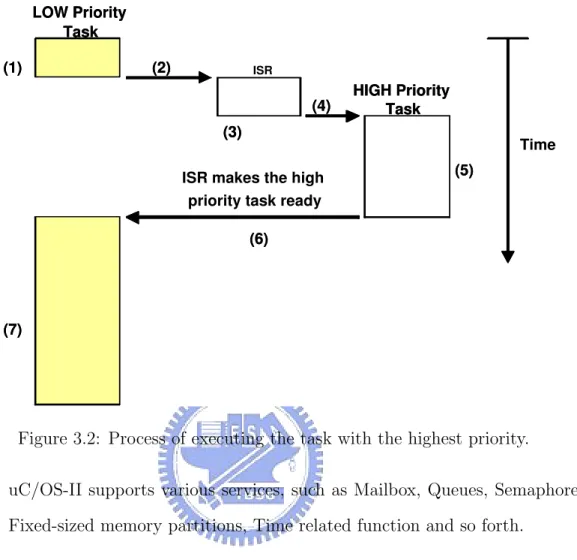
Figure 3.2: Process of executing the task with the highest priority.
uC/OS-II supports various services, such as Mailbox, Queues, Semaphores, Fixed-sized memory partitions, Time related function and so forth.
9. Interrupt Management
Interrupt could interrupt any task in process. There are 255 different level interrupts defined in uC/OS-II.
3.2.2
Modification
As long as we have a corresponding C Compiler, we could port uC/OS-II to specific a processor. Most porting is carried out in the content switching in multi-tasking. Saving and restoring value of register exemplify content switching process, which is completed by utilizing assembly langauge. To do content
switch-Status SP Priority . . . Task Control Block
TASK #1 Stack Status SP Priority . . . TASK #1 SP . . . SP . . . Status SP Priority . . . Task Control Block
TASK #2 Stack Status SP Priority . . . TASK #2 Status SP Priority . . . Task Control Block
TASK #n Stack Status SP Priority . . . TASK #n ... MEMORY CPU Figure 3.3: Multi-tasking.
ing for each processor, files need modifying are OS CPU.H, OS CPU C.C, and OS CPU A.S.
The following is to explain what modifications are required for these files: 1. OS CPU.H
(a) Definition of DATA TYPE (see Figure 3.4)
Data Type is relevant with what compiler being used because different compilers would take different amounts of bytes to represent an identical DATA TYPE. Take Integer as an example:
MS(VC++): 2 bytes GNU(gcc): 4 bytes (b) Stack Entry
Figure 3.4: DATA TYPES. task must be identical with the register of CPU. (c) Definition of stack growing direction
The growing direction of stack is from low memory address to high, or vice versa.
(d) Interruption and Content Switch (see Figure 3.5)
When running task is interrupted or content switch occurs, uC/OS-II must define which stack memory address in a stack that the register should be moved to.
2. OS CPU C.C (see Figure 3.6 and Figure 3.7)
In the initialized stack of a task, uC/OS-II will define each stack address, which is used to save register value.
3. OS CPU A.S
Some relevant CPU behaviors are defined in OS CPU A.S. We now turn to explain these behaviors in the following part.
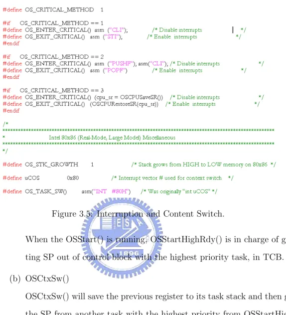
Figure 3.5: Interruption and Content Switch.
When the OSStart() is running, OSStartHighRdy() is in charge of get-ting SP out of control block with the highest priority task, in TCB. (b) OSCtxSw()
OSCtxSw() will save the previous register to its task stack and then get the SP from another task with the highest priority from OSStartHigh-Rdy(). Then OSCtxSw() will restores the value of register at CPU and keeps this task running.
(c) OSIntCtxSw() It defines the behaviors of the interrupted level of content switch.s
AX CX DX BX SP BP SI DI ES DS AX CX DX BX SP BP SI DI ES DS HIGH LOW
Figure 3.6: Initialized stack of a task.
3.3
lwIP
3.3.1
Overview
LwIP, a sort of TCP/IP, is utilized in embedded system. It reserves functions of TCP/IP and reduces the use amount of RAM. For instance, only 10 K RAM and 40K ROM will be consumed in the process. Based on these two features, even though resource is limited, better system efficiency could be maintained. In addition, because of its easy portability feature, we would also port it to uC/OS-II. The position of lwIP in protocol layering is shown in figure 3.8.
3.3.2
lwIP API
1. It supports Berkeley socket API
lwIP supports the Berkeley socket API utilized by general network program-ming. It would transform Berkeley socket API into the API that is designed
Figure 3.7: Initialized source code.
in lwIP. This transformation feature contributes to a significant compatibility for a developed program, as Figure 3.9 shows.
2. Communication between Application and TCP/IP protocol
In lwIP, the work of data receiving or transferring is taken by two different tasks. These two tasks utilize the mailbox provided by uC/OS-II to commu-nicate or transmit data between applications. Each mailbox is responsible for different jobs. For example, application could receive internet data packets from recvbox. Therefore, the exchange of information between the two tasks the application could be done by different mailboxes. Figure 3.10 clearly il-lustrates how communication is achieved between the TCP/IP Protocol and application by mailboxes.
ULP
Embedded System lwIP Protocol
uC/OS-II
Figure 3.8: lwIP Protocol Layering.
SOCKET API bind listen connect accept recv send write close lwip_API lwip_bind lwip_listen lwip_connect lwip_accept lwip_recv lwip_send lwip_write lwip_close netconn_API netconn_bind netconn_listen netconn_connect netconn_accept netconn_recv netconn_send netconn_write netconn_close
Figure 3.9: Transformation process of Berkeley socket API. 3. API types
There are four types of API provided by lwIP. The following part is going to introduce these four in details.
(a) TYPE 1: BIND, LISTEN, CLOSE
Type 1, illustrated in Figure 3.11, includes three types of operations, namely, BIND, LISTEN, CLOSE. We are now to explain them respec-tively as follow. First is about BIND method:
TASK 2 (data input) TASK 3 (tcpip_thread) mbox TASK 1 (application 1) recvmbox acceptmbox TASK 1 (application 1) recvmbox acceptmbox TASK N (application N) recvmbox acceptmbox TASK N (application N) recvmbox acceptmbox
Figure 3.10: Communication between Application and TCP/IP protocol.
TASK 2 mbox 1 2 3 4 msg ->type * API_MSG_BIND * API_MSG_LISTEN
Figure 3.11: API type 1.
a request to mbox, seen in Figure 3.11. Task 2, the task being responsible for transmitting data, will keep detecting whether there is any request in the mbox. At the meanwhile, the application will wait for the response from task 2.
ii. As long as there is a request found in mbox, task 2 will discriminate the request type and call the function responsible for this type of request. However, the request in every mbox could be different, such as examples in Figure 3.12, 3.13, and 3.14.
iii. Task 2 will immediately remit a response, whether successful or failure, to mbox.
whether the request is successful or not.
netconn_bind do_bind
API_MSG_BIND mbox
api_msg_post
api_msg_post sys_mbox_fetchsys_mbox_fetch sys_mbox_post sys_mbox_post sys_mbox_fetch
sys_mbox_fetch
tcp_bind
Figure 3.12: netconn bind.
Figure 3.12 shows that when the application operates a bind, it would send an API MSG BIND to mbox. Bind will call tcp bind function, which would build a relationship between application and the port. Hence, lwIP would know which application the incoming data belong to from the port.
netconn_listen do_listen
API_MSG_LISTEN mbox
api_msg_post
api_msg_post sys_mbox_fetchsys_mbox_fetch sys_mbox_post sys_mbox_post sys_mbox_fetch
sys_mbox_fetch
pcb ->accpet = accept_function
Figure 3.13: netconn listen.
Basically, the second method, called Listen, and third method, called close, follows the similar procedures (i) to (iv) above. Yet, there are still some slight differences between them: Listen would call accept funciton and then accept connection. Close would call tcp close and releases the occupied resource.
netconn_close do_close
API_MSG_CLOSE mbox
api_msg_post
api_msg_post sys_mbox_fetchsys_mbox_fetch sys_mbox_post sys_mbox_post sys_mbox_fetch
sys_mbox_fetch
tcp_close
(b) TYPE 2: CONNECT
Type 2 is the type of operation called CONNECT, illustrated in Figure 3.15 and Figure 3.16 below.
i. When application is going to connect to another node, ULP wil post a request to mbox. Task 2, the task being responsible for transmitting data, will keep detecting whether there is any request in the mbox.
ii. As long as there is a request found in mbox, task 2 will discriminate the request type and call the function responsible for this type of request. If the request type is discriminated as connect, task 2 will send a SYN packet to another node.
iii. When task 3, the task being responsible for receiving data, receives the acknowledgement of SYN, it will post the reply to mbox to inform application.
iv. After Application task receives the reply, it would know whether the connection is successful or not accordingly.
TASK 1 TASK 2 mbox 1 2 msg ->type * API_MSG_CONNECT TASK 3 3 4
netconn_connect do_connect pcb ->connected = do_connected pcb ->state = SYN_SENT tcp_enqueue () tcp_output () tcp_input () , tcp_process () switch case: SYNSENT pcb ->connected do_connected mbox api_msg_post api_msg_post sys_mbox_fetch sys_mbox_post sys_mbox_post sys_mbox_fetch sys_mbox_fetch
Figure 3.16: netconn connect.
data packet to another node by do connect. Application, at the mean-while, will wait for the reply. After do connected receives the acknowl-edgement of SYN, do connect will inform the application. Consequen-tially, connection will be established by Application.
(c) TYPE 3:SEND, WRITE
Type 3, including two types of operations, namely, SEND and WRITE, illustrated as Figure 3.17. TASK 1 mbox 1 2 3 4 msg ->type * API_MSG_SEND * API_MSG_WRITE TASK 2 udp_output or tcp_write
Figure 3.17: API type 3.
request to mbox. Task 2, the task being responsible for transmitting data, will keep detecting whether there is any request in the mbox. ii. As long as there is a request found in mbox, task 2 will discriminate the request type and call the function responsible for this type of request.
iii. Task 2 will immediately remit a response, whether successful or failure, to mbox.
iv. While Application task receives the reply from mbox, it would know whether the request is successful or not.
Examples are illustrated as Figure 3.18 and 3.19.
netconn_send do_send
API_MSG_SEND mbox
api_msg_post
api_msg_post sys_mbox_fetchsys_mbox_fetch sys_mbox_post sys_mbox_post sys_mbox_fetch
sys_mbox_fetch
udp_output
Figure 3.18: netconn send.
Whenever there is a UDP data to be sent, application will post the data and API MSG SEND to mbox. When there is a request in mbox found by task 2, it would call do send and transmit the data to another node by udp output.
netconn_write do_write
API_MSG_WRITE mbox
api_msg_post
api_msg_post sys_mbox_fetchsys_mbox_fetch sys_mbox_post sys_mbox_post sys_mbox_fetch sys_mbox_fetch tcp_enqueue tcp_output
data and API MSG WRITE to mbox. When there is a request in mbox found by task 2, it would call do write and transmit the data to another node by tcp output. However, before tcp output transmits data, task 2 would call tcp enqueue to make sure of TCP reliable mechanism. The packet in queue will be removed only when the data is correctly received. (d) TYPE 4: ACCEPT, RECV
Type 4 includes two operations. They are ACCEPT and RECV, illus-trated as Figure 3.20. TASK 3 TASK 1 1 2 acceptmbox or recvmbox TASK 2 mbox 3 4 5 6 msg ->type * API_MSG_RECV
Figure 3.20: API type 4.
i. When task 3 receives data, it would what application the received data packet belongs to according to the PCB. It would also post the data packet to acceptbox or recvbox.
ii. When there is any data packet found in acceptbox or recvbox, ap-plication would get the content in the data packet back. Because of TCP reliable mechanism, the application will transmit an ACK to source node to inform the success of sending data.
iii. When ULP is going to send ACK message, ULP will post a request to mbox. Task 2, the task being responsible for transmitting data, will keep detecting whether there is any request in the mbox. iv. As long as there is a request found in mbox, task 2 will discriminate
the request type and call the function responsible for this type of request.
v. Task 2 will immediately remit a response, whether successful or failure, to mbox.
vi. While Application task receives the reply from mbox, it would know whether the request is successful or not.
Examples are illustrated as Figure 3.21 and 3.22.
in tcp_process pcb ->accept accept_function netconn_accept acceptmbox sys_mbox_post sys_mbox_post sys_mbox_fetch sys_mbox_fetch
Figure 3.21: netconn accept.
The accept funtion will receive accepted reply and it will post the reply to accept box. When application receives the reply from the box, it would know that another node has accepted the connection.
After the application receives a data packet, it would send out an ACK to source node.
recv_tcp netconn_recv recvmbox do_recv mbox API_MSG_RECV in tcp_input () pcb ->recv sys_mbox_post sys_mbox_fetch api_msg_post api_msg_post sys_mbox_fetch sys_mbox_post sys_mbox_fetch sys_mbox_fetch
Let the stack know that we have taken the data
Figure 3.22: netconn recv.
3.4
RDMA Protocol
We are now to introduce RDMA protocol.
3.4.1
RDMA Operation
Two RDMA operations, read and write operations, are given as follows. 1. RDMA Write Operation
The sequence RDMA write operation is (see Figure 3.25):
(a) Application sink informs Application Source not only that it is ready to write but also the length of data.
(b) Application Source informs RDMA the memory address for later writ-ing.
(c) RDMA Engine informs STag, representing the known memory address, to Application Source.
Server
netconn_new netconn_bind netconn_listen netconn_accept netconn_recv netconn_write netconn_close do_bind do_listen accept_function recv_tcp do_write do_recv do_close mbox acceptmbox recvmbox mbox mbox mbox mboxTASK 1 TASK 2 TASK 3
Figure 3.23: The procedure of server.
(d) Application Source informs Application Sink the STag, which will be subsequently used in transmitting data.
(e) Application Sink informs RDMA Engine the STag and files to be trans-mitted.
(f) While transmitting data, RDMA Engine will include STag in the data packets being transmitting.
(g) Application Source utilizes RDMA Protocol to transmit the data to Application Sink.
(h) Application Sink RDMA Engine would directly write the data into the memory address known from the STag from the received data packets.
Client
netconn_new netconn_bind netconn_connect netconn_recv netconn_write netconn_close do_bind do_connect do_connected recv_tcp do_write do_recv do_close mbox recvmbox mbox mbox mbox mboxTASK 1 TASK 2 TASK 3
Figure 3.24: The procedure of client. process.
2. RDMA Read Operation
The sequence RDMA read operation is (see Figure 3.26):
(a) Application Sink informs RDMA Engine the memory address of the data to be received.
(b) RDMA Engine replies a STag to Application Sink.
(c) Application Sink transmits the STag to Application Source for subse-quent data transmitting. It would also inform Application Source for its readiness of file transmitting.
source RDMA Engine sink RDMA Engine data buffer (e) (i) (c) (a) (b) (g) (h) (f) (d)
Figure 3.25: RDMA Write Operation.
sink RDMA Engine source RDMA Engine buffer data (a) (h) (b) (c) (d) (f) (e) (g)
Figure 3.26: RDMA Read Operation. RDMA Engine.
(e) While transmitting data, RDMA Engine will include STag in the data packets being transmitting.
(f) Application Source utilizes RDMA Protocol to transmit the data to Application Sink.
(g) Application Sink RDMA Engine would directly write the data into the memory address known from the STag from the received data packets (h) Application Sink will wait for the completion of data transmitting
3.4.2
The flow chart of RDMA
In this section, we introduce the details for RDMA processes. 1. RDMA Write (See Figure 3.27)
Tx Data Rx Dest. R shm (1) write resq. (2) Post Address. (4) Pend Address. (3) register (5) STag (7) listen (6)Stag, Port (9) write (10) direct placement (8) Read Data
Figure 3.27: Flow chart of RDMA Write. (1) Source node sends a ”write resq” message to sink node.
(2), (3), and (4) Sink node posts a memory address to RDMA task and registers a STag.
(5) RDMA informs a STag to sink node.
(6) Sink node sends a STag and a port number to source node. (7) RDMA task will wait for connect.
(8), (9) Source node will connect to the RDMA task and write data to sink node.
(10) RDMA task would directly write the data into the memory address from STag from the received data packets.
2. RDMA Read (see Figure 3.28) Tx Data Rx Dest. R shm (1) Post Address. (3) Pend Address. (2) register (4) STag (6) listen (5) Stag, Port (8) write (9) direct placement (7) Read Data
Figure 3.28: Flow chart of RDMA Read.
In (1), (2), and (3), sink node posts a memory address to RDMA task and registers a STag.
(4) RDMA informs a STag to sink node.
(5) Sink node sends a STag and a port number to source node. (6) RDMA task will wait for connect.
(7), (8) Source node will connect to the RDMA task and write data to sink node.
(9) RDMA task would directly write the data into the memory address from STag from the received data packets.
3.4.3
RDMA and DDP API
Ac-Theoretically, as long as we complete the API of DDP, RDMA API could be com-pleted with minor modifications. Therefore, ULP could either transmit data by RDMA or DDP protocol or by Transport layer(TCP/IP) as shown in Figure 3.29g.
ULP (Upper Layer Protocol)
Transport DDP
RDMA
Figure 3.29: Protocol Layering.
1. DDP APIs
(a) ddp send(socket t s, message t m) Send an untagged message.
(b) ddp send ddp(socket t s, message t m, ddp addr t d, ddp notify t n) Send a tagged message to remote buffer address d.
(c) ddp post recv(socket t s, bdesc t b)
Post a registered buffer to accept a single received untagged message. Each buffer is returned to the caller in a ddp recv() untagged message reception indication, in the order in which it was posted. The same buffer may be enabled on multiple sockets, receipt of an untagged mes-sage into the buffer from any of these sockets unposts the buffer from all sockets.
Get the next received untagged message, tagged message reception in-dication, or tagged message error.
(e) ddp register(socket t s, ddp buffer t b)
Register a buffer for DDP on a socket. The same buffer may be regis-tered multiple times on the same or different sockets. The same buffer registered on different sockets may result in a common registration. Different buffers may also refer to portions of the same underlying ad-dressable object (buffer aliasing).
(f) ddp deregister(bhand t bh)
Remove a registration from a buffer. (g) ddp max msizes(socket t s)
Get the current maximum untagged and tagged message sizes that will fit in a single transport message.
2. RDMA APIs
(a) rdma send(socket t s, message t m)
Send a message, delivering it to the next untagged RDMA buffer at the remote peer.
(b) rdma write(socket t s, message t m, ddp addr t d, rdma notify t n) RDMA Write to remote buffer address d.
(c) rdma read(socket t s, ddp addr t s, length t l, ddp addr t d)
RDMA Read l octets from remote buffer address s to local buffer address d.
Post a registered buffer to accept a single Send message, to be filled and returned in-order to a subsequent caller of rdma recv(). As with DDP, buffers may be enabled on multiple sockets, in which case ordering guar-antees are relaxed. Also as with DDP, local interfaces must manage the mechanisms of allocation and management of buffers posted to multiple sockets.
(e) rdma recv(socket t s)
Get the next received Send message, RDMA Write completion identifier, or RDMA error.
(f) rdma register(socket t s, rdma buffer t b, bmode t mode)
Register a buffer for RDMA on a socket (for read access, write access or both). As with DDP, the same buffer may be registered multiple times on the same or different sockets, and different buffers may refer to portions of the same underlying addressable object.
(g) rdma deregister(bhand t bh)
Remove a registration from a buffer. (h) rdma max msizes(socket t s)
Get the current maximum Send (max untagged) and RDMA Read or Write (max tagged) operations that will fit in a single transport mes-sage. The values returned by rdma max msizes() are closely related to the values returned by ddp max msizes(), but may not be equal.
Chapter 4
Implementation and evaluation
In this chapter, we introduce our experimental environment and evaluate whether RDMA approach increases system efficiency or not.
4.1
Experimental environment
The experimental environment is composed of two parts: software tools and hardware tools. They are described as follows.
1. Software tools:
The software tools used to develop RDMA system are listed as follows.
• MIPS core GNU C++ 3.0: Because our developing platform utilizes
MIPS core, which is a kind of CPU, we have to take a complier which is compatible with our developing platform. Therefore, we choose MIPS core GNU C++ 3.0 to develop RDMA protocol.
• The API fo uC/OS-II and lwIP: It was used to develop the main frame
of our system. The version of uC/OS-II is 2.70u and version of lwIP is 0.53.
• MIDE: It was utilized to download a program to develop platform. It
could be used to display the value of register and memory, which are facilitative of debugging for programmers.
• HyperTerminal: It was utilized to receive message sent from com port
of develop platform. 2. Hardware environment:
Transmit node: It includes source node and sink node, which are defined according to functions they have in transmitting data. They used uC/OS-II as the Operation System (OS). In order to support TCP/IP Protocol, we used the 0.53 version of lwIP. Because the CPU in our develop platform could well handle the limited bandwidth, 10M bps, in network chip, we set option in OS to make the speed correspond to what CPU could actually deal with.
4.2
Evaluation and result
TCP/IP Protocol is taken in Network transfer in general. We would use two approaches, RDMA and TCP/IP, to transmit data and test whether or not RDMA can reach a better efficiency. As we have mentioned that different packet size might influence transmitting speed, therefore, packet size might be one of variables to be tested. We would take different packet sizes in these two approaches respectively and see whether it would make any differences in system efficiency.
Figure 4.2 and Figure 4.3 show how many ticks are needed in transmitting different packet sizes in TCP/IP and RDMA Protocol respectively.
Figure 4.3: Ticks taken in transmitting different packet sizes in RDMA protocol. When TCP/IP is transmitting data packets, data copy would happen in different protocol layers. This copy process would consume much system resource and take longer time. However, resource consuming and transmitting time would be less if packet size is small. In Figure 4.2, if we aim at packet number 5,000, we see different results. When the packet size is 50 KB, system would take 6,000 ticks. Likewise, when the packet size is 500KB, system would take 16,000 ticks and 1,400KB, 20,000 ticks.
If we utilize RDMA Protocol to transmit data, the content of data packets will be moved to a specific memory address by RDMA task. In this regard, prob-lems occur in using TCP/IP is avoided. Therefore, no matter what size the packet
is, the time taken in transmitting data would be the same.
In Figure 4.3, if we also aim at packet number 5,000, we see different results. When the packet size is 50 KB, system would take 11,000 ticks. Similarly, when the packet size is 500KB, system would take 11,000 ticks and 1,400KB, 11,000 ticks.
Figure 4.4 displays the result of transmitting data packet which is 1,400KB in TCP/IP and RDMA protocol.
Figure 4.4: Result of transmitting 1,400KB data packet in TCP/IP and RDMA protocol.
When transmitting 5,000 packets, the system would take 20,000 ticks in TCP/IP Protocol but 11,000 ticks in RDMA protocol. The tick amount taken in
4.4 shows.
Figure 4.5 shows the result of transmitting data packet which is 500KB in TCP/IP and RDMA protocol.
Figure 4.5: Result of transmitting 500KB data packet in TCP/IP and RDMA protocol.
When transmitting 5,000 packets, the system would take 16,000 ticks in TCP/IP Protocol but only 11,000 ticks in RDMA protocol. The tick amount taken in TCP/IP is nearly one and half times, compared with ticks taken in RDMA protocol, as Figure 4.5 illustrates.
Figure 4.6 shows the result of transmitting data packet which is 50KB in TCP/IP and RDMA protocol.
Figure 4.6: Result of transmitting 50KB data packet in TCP/IP and RDMA protocol.
When packet size is small, the resources consumed in data copy process are less. We could move a received packet to a specific memory address by STage in RDMA protocol. This process could be done without data copy. When transmit-ting 5,000 packets, the system would only take 6,000 ticks in TCP/IP Protocol but 11,000 ticks in RDMA protocol. The tick amount taken in RDMA protocol is almost double, compared with ticks taken in TCP/IP protocol, as Figure 4.6 shows.
Put above three results we found altogether, we would have Figure 4.7 as follows.
Figure 4.7: Conclusive Results.
From Figure 4.7, we conclude that the system efficiency is better when we transmit a relatively larger data packet by RDMA protocol. Yet, as far as a small packet as concerned, traditional method, TCP/IP Protocol, would have a better system efficiency.
Chapter 5
Conclusions
In this thesis, we have tested what approach would possibly increase the bandwidth in traditional network protocol environment. The RDMA protocol, approach taken in this thesis, is advantageous of avoiding the process of data copy as what TCP/IP usually does. However, results suggest that RDMA protocol would benefit system efficiency only in transmitting larger data packets whereas TCP/IP dose not. Therefore, in data cluster environment, RDMA protocol is one solution to problems occurred in the past and would thus increase more system efficiency.
For further thesis, two suggestions are given here. First, two APIs, uDAPL and kDAPL, are used to port RDMA protocol to Linux platform since they offer direct access mechanism. By combining these two APIs, we could implement RDMA protocol to Linux, which is an open source and has been widely utilized. Second, TCP Offload Engine (TOE) is mainly taking care of processing checksum of data packets in NIC. If TOE deals with its works along with RDMA protocol in NIC, system efficiency would be greatly increased.
Bibliography
[1] An overview of RDMA over IP [Online]. Available:
http://datatag.web.cern.ch/datatag/pfldnet2003/papers/
[2] Host-Assisted Zero-Copy Remote Memory Access Communication on Infini-Band [Online]. Available:http://nowlab.cis.ohio-state.edu/publications/conf-papers/
[3] P. Culley, and U. Elzur, and R. Recio, and S. Bailey, and J. Carrier, ”Marker PDU Aligned Framing for TCP Specification”, draft-ietf-rddp-mpa-01.txt, De-cember. 2003.
[4] H. Shah, and J. Pinkerton, and R. Recio, and P. Culley, ”Direct Data Place-ment over Reliable Transports”, draft-ietf-rddp-ddp-02.txt, February. 2004.
[5] Design and
implementation of RDMA as a best-efforts service and providing reliability over it [Online]. Available: http://www.stanford.edu/ priyank9/projects/ [6] Design and Implementation of the lwIP TCP/IP Stack [Online]. Available:
http://www.sics.se/ adam/lwip/
[7] R. Recio, and P. Culley, and D. Garcia, and J. Hilland, ”An RDMA Protocol Specification”, draft-recio-iwarp-rdmap-v1.0, October. 2002.
[8] H. J. Chu, ”Zero-Copy TCP in Solaris”, Proceedings of the USENIX Annual
Technical Conference, January. 1996.
[9] MicroC/OS-II, The Real-Time Kernel [Online]. Available:
http://www.infineon.com/cmc upload/documents/